RSS

Blog posts of '2026' 'October'

Mortise Lock Repair: What Fails and What You Can Replace

Quick Summary

Key points

  • Most mortise lock faults are trim, spindle or strike problems rather than faults inside the lock case, and the three are easy to tell apart once the door is open.
  • Test with the door open before anything else. A lock that works perfectly with the door open and fails when it is closed has a frame problem, not a lock problem.
  • The lock case, the trim, the cylinder and the strike are all ordered separately, so a failure in one does not force a complete lockset.
  • Rounded spindles are the single most common mechanical failure, because the spindle takes every turn of the lever and is softer than the hub it drives.
  • A case that is genuinely worn out is worth replacing rather than repairing, and the function code on the existing lock decides which case to order.
Where mortise lock faults actually sit
SymptomUsual locationCase fault?
Lever droops or spins freelySpindle or hubSometimes
Key turns but nothing movesCylinder or camRarely
Latch sluggish returningCase, or dirt in the caseOften
Will not latch when door closesStrike alignmentNo
Deadbolt throws but will not retractBinding against the strikeRarely

Mortise locks are built to be serviced. The case comes out of the door, the trim comes off the faces, the cylinder unscrews and the strike unscrews from the frame. Every one of those is a separate part, which is why a mortise lock repair is usually a component job rather than a replacement job.

What makes these calls go wrong is diagnosing from the symptom instead of from the door. This guide covers how to find the actual fault, what can be repaired, what cannot, and what to confirm before ordering.

What Usually Fails Inside a Mortise Lock?

Less than people expect. The case is a steel box full of levers and springs, and on a normal opening it will outlast several sets of trim.

What fails first is whatever is softest and most used. The spindle, because it transmits every turn of the lever. The hub, because the spindle wears into it. Springs, because they cycle constantly. And the latch bolt face, because it rubs against the strike every time the door closes.

Does a mortise lock wear out from the outside in?

Usually, yes. Damage arrives through the trim, the lever and the key, and works inwards. That is why the parts closest to the user fail first and the parts deepest in the case last the longest, and why a lock that feels rough at the lever is more often a trim job than a case job.

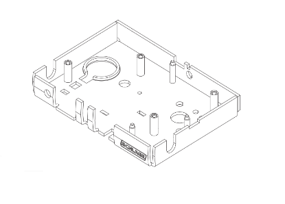
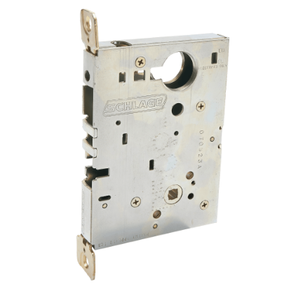
Schlage L283-112 mortise lock case for L9000 Series mortise lock repair
A basic mortise lock case. The case is supplied on its own, so a worn out mechanism does not drag the trim, cylinder and strike into the order with it.

How Do You Tell a Lock Fault From a Door Fault?

Open the door and work the lock in free air.

With the door open, operate the lever, throw and retract the deadbolt, and turn the key through its full travel. Everything the lock does with the door open is the lock. Anything that only goes wrong when the door is closed belongs to the frame, the strike or the door itself.

That single test resolves a large share of mortise lock calls before any tools come out, and it stops perfectly good locks being replaced because a door had dropped a few millimetres on its hinges.

The door open test and what each result means
Door openDoor closedWhere the fault is
Works correctlyFailsStrike, frame or door alignment
Rough or stickyAlso roughInside the lock, or the trim driving it
Lever free, latch stillSameSpindle or hub
Key turns looselySameCylinder or cam
Deadbolt throws freelyDeadbolt jamsStrike cutout position

What if the fault is intermittent?

Intermittent faults on an otherwise sound lock are usually environmental. A timber door that swells in humid weather, a frame that moves with temperature, or an exterior opening where debris is finding its way into the case. Note when it happens rather than only what happens, because the pattern is the diagnosis.

Can a Mortise Lock Be Repaired, or Does It Need Replacing?

Both are routine. The question is which part has failed and how much of the rest has aged alongside it.

Repair is the right route when a specific component has failed on a lock that is otherwise sound: a spindle, a spring, a trim plate, a cylinder, a strike. Replacement of the case makes sense when the mechanism itself is worn, when several parts have already been changed, or when the function needs to change.

When does the function decide the answer?

Whenever the room has changed use. A store that becomes an office, or a classroom that needs a different locking behaviour, is a function change rather than a repair. The lock case carries the function, so that is a case order, and the trim and cylinder may well carry over.

Our lock function codes guide covers how the function is expressed in the model number, which matters because two visually identical locks can behave completely differently.

Schlage L283-133 mortise lock case for L9050, L9060, L9070 and L9071 functions
A lock case listed against specific function codes. The case is where the function lives, which is why a function change is a case order rather than a trim order.

How Do You Get the Lock Case Out Without Damaging the Door?

In order, and with the door supported.

Take the trim off both faces first, then the cylinder, then the faceplate screws at the door edge. The case then withdraws from the mortise pocket. Forcing a case out before the cylinder is clear is how cams get bent and how pocket edges get torn.

On a heavy door, wedge the leaf before you start. A door that swings while you have the case half out will take the weight of the case on the pocket edge.

What should you check while the case is out?

Four things, because the pocket is only open once. The condition of the mortise pocket itself, the state of the wiring if the lock is electrified, whether the faceplate is flat and undamaged, and whether the cylinder threads are clean. Finding any of those later means taking the lock out again.

If the trim is also being changed, our trim parts guide covers what is supplied separately on the face of the door.

What Does a Worn Spindle or Hub Do to the Lock?

It produces the most recognisable fault on any mortise lock: the lever turns, and nothing happens.

The spindle is the shaped bar that carries the turn from the lever through the door into the lock hub. It is the part under the most direct load, and it rounds off at the corners over time. Once it has rounded enough, it spins inside the hub instead of driving it.

A lever that turns a few degrees and then goes slack, or one that works intermittently depending on how hard you turn, is almost always a spindle. Replacing the lock case for that symptom is a common and expensive mistake.

Von Duprin 967480 lever spindle that carries the turn into a mortise lock hub
A lever spindle. The corners carry the whole load of the turn, so this is the part to inspect before suspecting anything inside the case.

How do you check a spindle without stripping the door?

Take one lever off and look at the spindle end. Sharp, square corners mean the spindle is sound. Rounded or twisted corners mean it has been slipping, and the hub it drives needs looking at as well, because a worn spindle wears the hub it turns in.

Replacing a rounded spindle and leaving a worn hub gives you a repair that fails again quickly. If both are worn, the case goes on the order with the spindle.

Why Does the Deadbolt Throw but Not Retract?

Nearly always because it is under load from the strike rather than because the lock has failed.

When a door has dropped, or the frame has moved, the deadbolt enters its cutout at an angle and jams against the edge. The key then has to overcome that binding as well as turning the mechanism, and at some point it will not.

The test is simple. Open the door, throw the deadbolt and retract it. If it moves freely in free air, the lock is fine and the frame needs attention. Our mortise lock strike guide covers how the strike is dimensioned for the bolt it receives.

Can you force a jammed deadbolt?

You can, and it is how bolts get bent and keys snap in cylinders. Lift or push the door slightly to take the load off the bolt first, then turn the key. If it releases, you have both diagnosed and temporarily solved the problem in one movement.

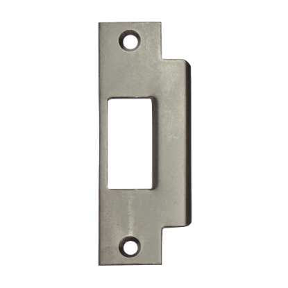
Von Duprin 575 mortise lock strike for a mortise latch and deadbolt
A mortise lock strike. The strike receives both the latch and the bolt, so a strike in the wrong position creates two separate symptoms that look like two separate faults.

What Parts Are Stocked Separately for Mortise Lock Repair?

Enough that a complete lockset is rarely the answer.

Mortise lock components supplied as separate items
PartWhat it doesTypical reason to order it
Lock caseCarries the mechanism and the functionWorn mechanism or a function change
SpindleDrives the hub from the leverRounded corners, lever spinning
Trim and leverUser facing hardwareImpact damage or accessibility change
CylinderKeyingRekeying, lost keys, worn plug
StrikeReceives latch and boltAlignment, damage, frame change
Screw packRefittingWorn or missing fixings after service

Screw packs matter more than they look. Refitting a serviced lock with mixed fixings from the van is how the next technician finds a lock that has worked loose in its pocket.

Schlage 47279023 L9000 screw pack for refitting a repaired mortise lock
A screw pack listed against a specific lock series. Fixings are specified for the hardware, which is why they are stocked rather than substituted.

Is the cylinder part of the lock?

No, and that is useful. The cylinder is a separate item with its own cam, which means rekeying an opening never touches the lock case. Our mortise cylinder and rim cylinder comparison covers how the two differ and why the cam matters.

What Should You Confirm Before Ordering Repair Parts?

Six things, and they come off the door rather than out of a catalogue.

The lock series, from the stamping on the case or faceplate. The function, because it decides the case. Which component has actually failed, established by the door open test. The handing, where the part is handed. The finish, because visible parts have to match the rest of the opening. And whether the lock is electrified, because that changes both the case and the wiring arrangement.

What if the lock is unmarked?

Measure and photograph. The backset, the case dimensions, the faceplate size and the arrangement of the latch and bolt together narrow the family quickly. A photograph of the case out of the door, with a tape measure across the faceplate, is usually enough to confirm the part.

For a wider view of the range, our mortise lock parts guide lists components by function, and the commercial mortise locks guide covers how these locks are specified in the first place. If you are still establishing which family of lock is on the door, start with mortise locks versus cylindrical locks.

About the Author

Security Parts has supplied repair parts for commercial door hardware since 2001, covering Von Duprin, LCN, Schlage, Falcon, Detex and Adams Rite at the component level. Our diagram based lookup exists so a technician can confirm a part before ordering it. This guide was written by the Security Parts team from supplier documentation and the questions our customers bring us.

Panic Bar Parts Diagram: How to Read It and Identify Parts

Quick Summary

Key points

  • Every panic bar breaks down into the same five groups: the touchpad or crossbar, the center case, the rail and baseplate, the end cap, and the latch assembly.
  • A parts diagram is read from the center outwards. The center case is where the mechanism lives, and almost everything else hangs off what the center case does.
  • The device type changes the latch group and nothing else. Rim, surface vertical rod, concealed vertical rod and mortise devices share most of the rail hardware.
  • Dogging parts fail more than anything else on a panic bar, because they are used daily and the socket or the cylinder takes the wear.
  • Almost every item on the diagram is stocked individually, so a damaged device is normally a parts order rather than a replacement device.
The five part groups on a panic bar
GroupWhere it sitsWhat it does
Touchpad or crossbarAcross the face of the doorThe surface the user pushes
Center caseMiddle of the deviceHolds the mechanism and the dogging
Rail and baseplateFull width of the deviceCarries the device and fixes it to the door
End capHinge end of the railCloses the rail and anchors that end
Latch assemblyLatch end, top or bottomEngages the strike or the frame

Panic bar parts diagrams look intimidating because they show fifty numbered items on one page. In practice the device only has five groups, and once you can place a part into its group the diagram stops being a wall of numbers.

This guide walks through those groups in the order a diagram is normally laid out, explains what each one does, and covers how the picture changes between device types.

What Are the Main Parts of a Panic Bar?

A touchpad or crossbar, a center case, a rail with a baseplate, an end cap, and a latch assembly. Everything else on the diagram is a fixing, a spring, a cover or a bracket serving one of those five.

The sequence matters because that is how the force travels. A user pushes the touchpad, the touchpad drives the mechanism in the center case, the center case pulls the latch, and the latch leaves the strike. The rail and end cap hold the whole assembly on the door while that happens.

What does the rail and baseplate group do?

The baseplate is the plate that fixes to the door face, and the rail is the cover that runs along it. Between them they carry the device, set how far it stands off the door, and give the touchpad something to react against.

It is the group people ignore on a diagram, and the group that quietly causes the most puzzling faults. Baseplate screws that have worked loose let the whole device move a fraction every time the bar is pushed, which shows up as a latch that retracts fully one day and not the next. Checking that the baseplate is tight against the door is a thirty second job that saves a long diagnosis.

Is a panic bar the same as an exit device?

Panic bar is the common name, exit device is the term used in product literature, and in everyday use they refer to the same hardware. There is a meaningful distinction in how devices are labelled and listed for different applications, which our exit device and panic bar comparison covers in detail.

What Does the Center Case Do?

It is the gearbox. The center case takes the movement of the touchpad and converts it into the pull that retracts the latch, and on most devices it also houses the dogging mechanism.

Because the mechanism lives there, the center case is the part that determines what the device can do. Dogging, cylinder dogging, alarm modules and electrified retraction all attach to or sit inside this group. That is why two devices with identical rails can behave completely differently.

Von Duprin 050564 center case cover bracket from the middle of a panic bar
A center case cover bracket. Covers and brackets are listed separately from the case itself, which is why a damaged cover is a small order rather than a device replacement.

Why is the center case reinforced?

Because it carries the concentrated load. A rail spreads force across the door, but the center case takes the whole pull of the latch mechanism at one point. Reinforcing brackets exist to transfer that load into the door rather than leaving it on the baseplate fixings.

On a door that is kicked, barged or propped regularly, the reinforcement is the part that keeps the center case flat against the door. A center case that has started to lift is the early warning of a device that will fail entirely.

What Is Inside the End Cap?

Less than people expect, and that is the point. The end cap closes the hinge end of the rail, anchors the rail to the door and keeps the internal components enclosed.

It is also the part most likely to be damaged, because it sits at the end of a long lever and takes impacts from trolleys, furniture and the wall. Impact resistant versions exist specifically for openings where that is routine.

Von Duprin 900397 metal end cap kit for the hinge end of a panic bar rail
A metal end cap kit. End caps are supplied as kits with their fixings, because replacing the cap without the correct screws is how the next one works loose.

Does a missing end cap matter?

Yes, on two counts. It exposes the internals of the rail to dirt and interference, and it removes an anchor point, which lets the rail flex when the touchpad is pushed. A device with a flexing rail will eventually stop retracting the latch fully.

How Does the Latch Assembly Work?

The latch is pulled back by the mechanism, held back while the touchpad is depressed, and sprung forward again when the touchpad releases.

Three components do that work: the latch itself, the latch tail that connects it to the mechanism, and the spring that returns it. All three are stocked separately, and the spring is usually the first to go.

A latch that retracts but returns slowly is a spring. A latch that retracts partially is usually the tail or the linkage. A latch that does not move at all with a working touchpad is a center case fault.

Von Duprin 050500 latch tail, spring and rivet kit from a panic bar latch assembly
A latch tail, spring and rivet kit. Supplied together because they wear together, and because a new spring in an old tail rarely holds its adjustment.

Why does the latch group change between devices?

Because the latch has to reach something different. A rim device latches into a strike on the frame. A surface vertical rod device drives rods up and down to latch at the head and sill. A concealed vertical rod device does the same with the rods inside the door. A mortise device drives a lock case in the door edge.

Everything from the touchpad to the center case is largely common across those four. The latch group is where they diverge, which is why diagrams for different device types look similar until the right hand end. Our concealed vertical rod guide covers the most complex of the four.

What Is Dogging and Which Parts Control It?

Dogging holds the touchpad depressed and the latch retracted, so the door becomes push and pull during the hours the building wants it open.

Two methods are common. Hex dogging uses a hex key in a socket to drive a shaft that holds the mechanism. Cylinder dogging uses a keyed cylinder to do the same job, so only key holders can set it.

Dogging methods and the parts involved
MethodHow it is setParts that wear
Hex doggingHex key in a socketShaft, socket, spring and guide
Cylinder doggingKeyed cylinderCylinder, cam, plug and bracket
Electric latch retractionSignalled from the panelMotor, cable and harness
No doggingNot fittedPlug fills the socket position
Von Duprin 090043 dogging adaptor shown in a panic bar parts diagram
A dogging adaptor. Supplied in pairs, which tells you something about how often these wear on devices that are dogged every morning.

Can a device be converted between dogging types?

Often, using a conversion kit. Moving from hex to cylinder dogging is a common request on sites that want to stop staff dogging doors informally, and the conversion is a parts order rather than a new device. The reverse conversion also exists.

One point worth confirming first: dogging is not permitted on every opening. A fire rated opening has to latch, so a dogged device on a fire door is a defect rather than a convenience.

Why Does the Touchpad Feel Loose or Noisy?

Usually because of what sits behind it rather than the pad itself.

The touchpad travels every time somebody uses the door, and it stops against the body of the device at the end of that travel. Shock absorbing components take that impact. When they fail, the pad bottoms out metal against metal, which is both the noise people report and a load path into the mechanism that was never intended.

Von Duprin 050491 shock absorber package fitted behind a panic bar touchpad
A shock absorber package. A small part that stops the touchpad striking the device body, and a common cause of a bar that has become noticeably louder.

Is a noisy panic bar a safety problem?

Not in itself, but it is a sign of wear that eventually becomes one. A touchpad that has lost its cushioning transmits full impact into the linkage every cycle, and on a busy door that is hundreds of impacts a day. Fixing it at the noise stage is far cheaper than fixing it at the failure stage.

Which Panic Bar Parts Fail Most Often?

In rough order: dogging components, end caps, springs, touchpad cushioning, and latch tails.

Common failures and what they look like on the door
PartSymptomUsual cause
Dogging shaft or socketHex key slips, will not hold doggedDaily use, worn socket
End capLoose, missing or crackedImpact at the hinge end
Latch springLatch returns slowly or not fullyFatigue
Shock absorberLoud bar, hard stop at the padWear from cycling
Baseplate screwsRail lifts off the doorLoosening under load

None of those require a new device. For the full Von Duprin component listing, our Von Duprin panic bar parts guide and 98 and 99 Series parts guide set the numbers against the groups described here.

What about double doors?

A pair of doors adds the mullion or the overlapping astragal arrangement to the picture, and with it another set of parts that can fail independently of the devices. Our mullion guide covers the removable mullion, which is the most commonly misdiagnosed component on a pair.

How Do You Identify a Part From a Diagram?

Place it in its group first, then match the shape, then confirm the series.

Group narrows the field from fifty items to about eight. Shape narrows it further. The series then decides which of the remaining candidates is the correct number, because the same looking bracket exists in several series with different numbers.

What if the device series is unknown?

Read the stamping, usually found on the baseplate under the rail or on the end cap. If the device has been painted over, the dimensions of the center case and the type of latch group between them identify the family in most cases.

Photographs are worth more than descriptions here. A picture of the device on the door, a second of the latch end, and a third of any visible stamping will usually settle it. Our panic bar selection guide covers how the series are distinguished, and the exit device installation guide covers the mounting arrangement that the diagram assumes. If you are starting from the user side rather than the parts side, our crash bar overview is the better starting point, and panic hardware on commercial doors covers where these devices are required.

About the Author

Security Parts has supplied repair parts for commercial door hardware since 2001, covering Von Duprin, LCN, Schlage, Falcon, Detex and Adams Rite at the component level. Our diagram based lookup exists so a technician can confirm a part before ordering it. This guide was written by the Security Parts team from supplier documentation and the questions our customers bring us.

Von Duprin 6211 Electric Strike: Variants, Parts and Faults

Quick Summary

Key points

  • The 6211 is a 6200 Series heavy duty electric strike for single doors, working with mortise locks without deadbolts and with cylindrical locksets that have a 3/4 inch latchbolt throw.
  • Three variants share the same model number. The base 6211 and the 6211AL are listed for aluminium frames with a 1-11/16 inch backbox depth, and the 6211WF is built for wood frames with a 4-1/2 inch backbox depth.
  • All three carry a 4-7/8 inch by 1-1/4 inch faceplate, take 24 VDC as standard with 12 and 16 VDC options, and ship fail secure with fail safe available.
  • Mode is not soldered in. A slider sets fail safe on the WF, which is why a strike can behave differently from the one next to it on an identical opening.
  • Most faults on these strikes are mechanical rather than electronic. Springs, keepers and faceplates are stocked separately, so a tired strike rarely needs replacing whole.
The three 6211 variants at a glance
VariantFrame type listedBackbox depthRetrofit reference
6211Aluminium frame1-11/16 in.VD 3140 or FA 712
6211ALAluminium frame1-11/16 in.FA 722
6211WFWood frame4-1/2 in.FA 732

A Von Duprin 6211 electric strike enquiry almost always starts the same way. Somebody has a strike in a frame, a number stamped on it that reads 6211, and a part that has stopped doing its job. Then it turns out there are three units sharing that number, and they are not interchangeable.

This guide sets out what the 6211 actually is, how the three variants differ, which parts are supplied separately, and what to establish before ordering anything.

What Is the Von Duprin 6211 Electric Strike?

The 6211 is a heavy duty electric strike from the 6200 Series, designed for single door openings. It gives remote release of a locked door: the lock stays locked, and the strike lets the latch out of the frame when it is signalled.

That distinction matters more than it sounds. An electric strike does not unlock the lock. The lever or knob on the secure side behaves exactly as it did before, and the key still works as it did. What changes is the frame side of the opening, which can now be released from a button, a reader or an access control panel.

What locks does a 6211 accept?

Mortise locks without deadbolts, and cylindrical locksets, provided the latchbolt throw is 3/4 inch. That throw figure is the one to check first, because a latch that projects further will not sit correctly in the keeper and a shorter one may not be held at all.

If you are not certain which family of lock is on the door, our mortise locks versus cylindrical locks guide walks through the visible differences at the door edge.

Von Duprin 6211 electric strike for 6200 Series mortise lock openings
The base 6211. The faceplate measures 4-7/8 inches by 1-1/4 inches, which is the dimension to measure before assuming a replacement will drop into the existing frame cutout.

What Is the Difference Between 6211, 6211AL and 6211WF?

The suffix carries the frame the strike was built for, and with it the depth of the hole the frame needs.

The base 6211 and the 6211AL are both listed for aluminium frames with a 1-11/16 inch backbox depth. The 6211WF is the wood frame unit, and its backbox depth is 4-1/2 inches. That is not a small difference. A WF will not go into a prep cut for an AL, and an AL dropped into a WF cutout will sit in a hole far deeper than it needs.

Von Duprin 6211AL electric strike with aluminium frame faceplate
The 6211AL. Same 3/4 inch throw and same faceplate size as the base unit, with the aluminium frame backbox depth of 1-11/16 inches.

Do the three share any parts?

Some, and that is where part numbers earn their keep. A single stocked spring kit covers both the 6211 and the 6216, for example, while faceplates are listed per variant. Shared mechanical parts are the reason a strike that has lost its spring tension does not need a new body.

Von Duprin 6211WF electric strike built for wood frame openings
The 6211WF, built for wood frames in stainless steel. The 4-1/2 inch backbox depth is the figure that decides whether this unit can go where the old one came out.

Is the 6211 Fail Safe or Fail Secure?

Fail secure as standard, with fail safe available as an option. In plain terms, remove the power from a fail secure strike and the door stays locked from outside. Remove it from a fail safe strike and the strike releases.

Neither setting affects getting out. Egress happens through the lock on the inside of the door, which is mechanical, so somebody inside can always leave whatever the strike is doing.

What each mode does when power is removed
ModeOn power lossCurrent draw in normal stateTypical reason to choose it
Fail secureStrike holds the latch, door stays locked from outsideNone until releasedStores, plant rooms, anything that must stay secure in an outage
Fail safeStrike releases, latch can leave the keeperContinuous while lockedDoors that have to open on an alarm or outage

How do you set the mode on a 6211WF?

With a slider. Von Duprin lists a fail safe slider as a separate stocked part for the 6211WF, which means the mode is set by a physical component rather than by a different model number.

Two consequences follow. A strike ordered in one mode can be moved to the other without replacing the unit, and a strike behaving unexpectedly on site may simply have been set the other way at some point in its life. Check the slider before condemning the strike.

Von Duprin 090798 fail safe slider that sets 6211WF electric strike mode
The 090798 fail safe slider for the 6211WF. A stocked part, which is the clue that mode is a field setting rather than a permanent property of the strike.

What Voltage Does a 6211 Need?

The standard listing is 24 VDC, with 12 VDC and 16 VDC available as options. The figure on the strike has to match what the power supply actually delivers at the door, not what it says on the label in the cupboard.

Voltage drop over a long run is the usual culprit when a strike buzzes but does not release. A unit that works on the bench and fails in the frame is rarely faulty. Our electric strike schematic guide covers how the supply, the release device and the strike sit together on a circuit.

Does a fail safe strike draw more current?

In its normal state, yes, because it is held locked by power. A fail secure strike sits idle until somebody releases it. On a site with a battery backed supply, that difference decides how long the supply carries the opening in an outage, so it belongs in the calculation rather than being discovered later.

Which Faceplate Does a 6211 Need?

The listed faceplate for the 6211 family is 4-7/8 inches by 1-1/4 inches. Faceplates are supplied as separate parts, which is useful in two situations: a faceplate damaged by a strike plate removal, and a change of finish on an opening being refurbished.

Faceplates are not universal across the electric strike ranges. A faceplate listed for the 5100 is a 5100 part, not a 6200 part, and the same is true of the 6100. Our Von Duprin electric strike parts guide sets out which part families sit under which series.

Von Duprin 050939 spring kit for 6211 and 6216 electric strikes
The 050939 spring kit, listed for the 6211 and the 6216. Spring kits are one of the few parts shared across two models, which is worth knowing when a strike has gone sluggish rather than dead.

What Parts Fail on a 6211 Electric Strike?

The electronics are the part people suspect first and the part that fails last.

A strike lives in a frame, takes the impact of a closing door several hundred times a day on a busy opening, and holds a latch under load whenever somebody leans on the door. The parts that give up reflect that: springs lose tension, keeper surfaces wear, faceplates get bent by levering, and fixings work loose in the frame.

Reading the symptom back to the likely part
SymptomLikely causeWhat to check
Strike clicks but the door will not push openLatch binding in the keeperDoor alignment and latch throw against the 3/4 inch figure
Keeper does not return cleanlySpring tension lostSpring kit for the 6211 and 6216
No sound and no releaseSupply, release device or wiringVoltage at the strike while the release is pressed
Releases with no signalMode set to fail safe, or supply interruptedSlider position on a WF, and the supply itself
Faceplate no longer sits flushFrame damage or bent faceplateFaceplate as a separate part before replacing the strike

How do you diagnose a 6211 that will not release?

Work from the supply outwards, and measure rather than assume.

Prove the release device is sending a signal. Then measure the voltage at the strike terminals while the release is operated, not at the panel. Then take the load off the strike by pulling the door open slightly and operating the release again, because a latch under side load can hold a keeper that is actually working.

Only when all three have been checked does the strike itself become the suspect. That sequence saves a great many strikes that were never faulty. The same logic applies across the range, and our complete electric strikes guide covers it in more depth.

What Goes Wrong at Installation?

Three things, repeatedly.

The first is backbox depth. The 4-1/2 inch depth of a WF against the 1-11/16 inch depth of an AL is the single most common reason a replacement strike will not go in. Measure the existing cavity before ordering.

The second is latch alignment. The strike is cut into the frame in a fixed position, so the door has to present its latch at the right height. A door that has dropped on its hinges will push its latch against the edge of the keeper.

The third is the mode assumption. A strike fitted fail secure on a door the building expects to release in an alarm is a specification error that will not show up until the day it matters. Our electric strike installation guide covers the sequence in full.

Does the 6211 suit every single door opening?

No. It is listed for mortise locks without deadbolts and for cylindrical locks with a 3/4 inch throw, on a 1-3/4 inch door. A mortise lock with a deadbolt, a different throw, or a pair of doors without a mullion all take the opening outside what this unit was designed for.

Where the opening falls outside those limits, another series usually covers it. Our 6100 Series parts guide and 5100 Series parts guide set out where each one applies.

What Do You Need to Confirm Before Ordering 6211 Parts?

Six things, and five of them are read off the door rather than looked up.

The ordering checklist for a 6211 electric strike
CheckWhy it decides the part
Exact variant stamped on the unit6211, 6211AL and 6211WF are different parts
Frame material and existing cavity depth1-11/16 in. against 4-1/2 in. decides what will fit
Lock type and latchbolt throw3/4 inch throw, mortise without deadbolt or cylindrical
Voltage available at the door24 VDC standard, 12 and 16 VDC options
Mode the opening requiresFail secure standard, fail safe optional
Whether the fault is mechanical or electricalDecides between a spring kit, a faceplate and a new unit

What if the number on the strike is unreadable?

Measure instead. The faceplate dimensions, the cavity depth and the frame material between them narrow the field quickly, and the latch throw on the door confirms whether the opening belongs to this family at all. A photograph of the faceplate and a tape measure reading of the cavity are usually enough for us to confirm the part.

For a broader view of which components exist across the electric strike ranges, our electric strike parts guide lists them by function rather than by model.

About the Author

Security Parts has supplied repair parts for commercial door hardware since 2001, covering Von Duprin, LCN, Schlage, Falcon, Detex and Adams Rite at the component level. Our diagram based lookup exists so a technician can confirm a part before ordering it. This guide was written by the Security Parts team from supplier documentation and the questions our customers bring us.

How to Align a Door Strike Plate: Diagnosis and Fixes

Quick Summary

Key points

  • A strike plate that is out of alignment by a couple of millimetres is enough to stop a door latching, and the fault is almost never the lock.
  • Work out the direction first. Too high, too low, too shallow or too deep each have a different fix, and the lipstick or marker test shows you which within a minute.
  • Shallow misalignment is a shim or a filed strike. Deep misalignment usually means the door has moved on its hinges, and moving the strike only hides that.
  • The deadlocking plunger has to land on the strike plate face, not drop into the cutout. An opening that latches but can be pushed back is an alignment fault, not a lock fault.
  • On a fire rated opening, filing, packing and enlarging holes are not free choices. The assembly was tested as a set, so replacement parts rather than modification is the route.
Reading the symptom before you touch anything
What the door doesMost likely alignment faultFirst thing to check
Latch hits the strike face and bouncesLatch sitting too high or too lowWitness mark on the strike plate
Door has to be pulled to lockStrike too far into the frameGap between door face and stop
Latch enters but the door rattlesStrike too far out of the frameMovement at the lock edge with the door shut
Latches, but can be pushed back openPlunger dropping into the cutoutWhere the plunger lands on the plate
Catches only in warm weatherDoor or frame movement, not the strikeHinge screws and frame fixings

A door that will not latch is one of the most common calls in commercial door hardware, and one of the most commonly misdiagnosed. The lock gets replaced, the latch gets replaced, and the door still bounces back off the frame, because the problem was never in the door at all.

This guide covers how to align a door strike plate properly: how to find the direction of the error, how to correct it, when to move the strike and when to leave it alone, and what changes on a fire rated opening.

What Does It Mean to Align a Door Strike Plate?

Alignment means the latch arrives at the strike opening squarely, enters it without touching the edges, and projects far enough into the frame to hold.

Three dimensions have to be right at once. Height, so the latch meets the cutout rather than the plate above or below it. Depth, so the latch projects into the frame by its full throw with the door closed against the stop. And squareness, so the latch is not entering at an angle that loads one side of the cutout.

Get any one of them wrong and the door reports it differently, which is why the direction of the error matters more than the fact of it. If the strike plate itself is unfamiliar, our strike plate guide covers the component before the adjustment.

Is this the same as adjusting a door strike plate?

In practice people use both phrases for the same job. Adjusting tends to mean small corrections to an existing strike. Aligning covers the whole exercise, including deciding that the strike is in the right place and the door is not.

Schlage 10-025 ANSI strike used when you align a door strike plate to the latch
A standard ANSI strike. The cutout has to receive the latch cleanly across its full throw, which is what alignment is actually about.

How Do You Know Which Direction the Strike Is Out By?

Mark the latch and let the door tell you.

Put a line of marker, chalk or lipstick across the face of the latch bolt, close the door normally, and open it again. The transfer mark on the strike plate shows exactly where the latch is landing. A mark above the cutout means the latch is sitting high. A mark below it means low. A mark on the lip means the latch is arriving at an angle or the door is not reaching the stop.

The test takes a minute and removes the guesswork that leads to filing a strike that was never in the wrong place.

What if the mark lands inside the cutout but the door still will not latch?

Then the problem is depth rather than position. The latch is finding the hole but not projecting far enough into the frame to be held. That usually means the door is stopping short, and the gap between the door face and the frame stop is the measurement to take next.

What the witness mark is telling you
Where the mark landsWhat it meansUsual correction
Above the cutoutLatch is high relative to the strikeLower the strike or lift the door on its hinges
Below the cutoutLatch is low relative to the strikeRaise the strike or correct hinge sag
On the lip, towards the stopDoor is not closing far enoughCheck the stop, gasketing and closer
Inside the cutout, shallowLatch not fully enteringDeepen the mortise or shim the strike
Clean, no mark, door still looseStrike set too far outReset strike depth

How Do You Align a Door Strike Plate Step by Step?

Work in a fixed order so each step rules something out rather than introducing a new variable.

Start by checking the hinges. Every hinge screw tight, no movement at the leaf, no visible drop at the lock edge. A door that has sagged will present its latch low, and no amount of strike adjustment fixes a hinge.

Next, close the door slowly by hand and watch the latch meet the frame. Slow closing shows you things that normal closing speed hides, including a latch that is clipping the lip before it reaches the cutout.

Then run the marker test and read the direction. Only after that do you touch the strike.

How much can you move a strike plate?

Less than people expect, because the fixing holes constrain it. Small corrections are usually made by filing the cutout edge slightly, packing behind the plate, or replacing the strike with one whose cutout sits differently. Larger corrections mean repositioning the plate and plugging the old screw holes, which is a frame repair rather than an adjustment.

Von Duprin 970323 strike plate for a surface mounted exit device latch
A strike plate for a surface mounted exit device. On exit hardware the strike position is set by the device template, so alignment problems usually mean the device or the door has moved rather than the strike.

When Should You Shim a Strike Instead of Filing It?

Shim when the latch is not reaching far enough into the frame, or when the door sits loose against the stop with the latch engaged.

A shim strike is a stocked part rather than something to improvise from washers. Packing behind a strike with whatever is to hand changes how the plate sits in its recess, and a plate that is no longer flat will eventually loosen its fixings under impact.

File only when the latch is clipping a cutout edge by a very small amount, and only on a non rated opening. Filing removes material permanently and makes the hole larger in one direction, which is a one way adjustment.

Von Duprin 970321 shim strike used to adjust strike plate depth
A shim strike. Depth adjustment belongs to a made part rather than to packing improvised behind the plate, because the plate has to stay flat in its recess.

Does the strike box matter?

It does on hollow metal and timber frames. The box lines the cavity behind the plate, stops debris collecting in it, and gives the latch somewhere clean to sit. A missing or crushed box is a common reason a latch enters but does not sit properly, and it is easy to miss because the plate looks correct from outside.

Schlage 10-072-078 T-square corner strike supplied with its plastic strike box
A strike supplied with its plastic box. Worth lifting the plate to check, because a collapsed box behind a perfectly aligned strike produces exactly the same symptom as a misaligned one.

What Is the Deadlocking Plunger and Why Does Alignment Affect It?

It is the small auxiliary pin that sits beside the main latch bolt. When the door closes, the plunger is held in by the face of the strike plate, which in turn stops the main latch being pushed back from outside.

Alignment decides whether that works. The plunger has to land on the solid face of the plate. If it drops into the cutout alongside the latch, it is no longer held in, and the latch loses its deadlocking.

The symptom is specific and easy to recognise. The door latches, feels normal, and can then be pushed open by hand with moderate pressure. That is an alignment fault, not a lock fault, and no new lock will cure it.

Schlage 13-247 spring deadlatch showing the auxiliary plunger beside the latch bolt
A spring deadlatch. The smaller plunger alongside the main bolt is the part that has to meet the plate face, which is why strike position matters for security and not only for closing.

How do you check the plunger is landing correctly?

Close the door and look at the gap at the latch edge with a torch, or mark the plunger as well as the latch for the transfer test. If the plunger mark falls inside the cutout outline, the strike needs moving or replacing with one whose cutout is positioned differently relative to the plate face.

Our strike plates and deadlatches parts guide covers how the latch, plunger and plate are supplied as separate items.

How Do You Align a Strike Plate on a Fire Rated Door?

Carefully, and with replacement parts rather than modification.

A fire rated opening is tested and labelled as an assembly. The door, frame, hinges, closer, latch and strike were certified together, and site modification can take the assembly outside what was tested. Filing a strike cutout, enlarging holes or packing behind a plate with uncertified material all fall into that category.

What remains available is correcting the cause rather than the symptom: tightening or replacing hinges, correcting a sagging door, replacing a damaged strike with the correct listed part, and adjusting the closer so the door reaches the stop. Our fire rating guide covers what is and is not permissible on a rated assembly.

What about an accessible opening?

Alignment affects the force needed to open the door, which is a measured requirement on accessible routes. A latch that is binding in a misaligned strike adds resistance that a user has to overcome, so this is not purely a convenience issue. Our door clearance guide covers the dimensional requirements around the opening.

What Do You Do When the Screw Holes Are Worn?

Move to longer fixings into solid material, or plug and redrill.

Worn holes are common on openings that have been adjusted several times, and they produce a strike that creeps back out of position within weeks of being set. Retightening the same screws into the same enlarged holes is the one approach that reliably fails.

Screw packs are stocked as separate items for exactly this reason, and matching the drive type to the existing hardware avoids chewing the heads on the next visit.

Should the strike be reinforced?

On a high traffic opening, or one that has taken a forced entry attempt, a frame reinforcer spreads the load behind the plate instead of leaving it on the frame skin alone. It is worth considering whenever you are already taking a strike off a door that has a history of failing in the same way.

When Is the Strike Not the Problem at All?

More often than the call suggests. Several faults present as a door that will not latch, and three of them live elsewhere.

Faults that look like strike misalignment
Actual causeHow it presentsHow to tell
Hinge wear or loose screwsDoor drops, latch arrives lowLift the door at the lock edge and watch for movement
Closer latch speed too slowDoor rests against the stop without latchingPush the door shut by hand, it latches
Gasketing or seals too thickDoor stops short of the frameMeasure the gap at the stop
Latch itself sluggishLatch does not spring out fullyOperate the latch with the door open
Frame movementIntermittent, often seasonalBehaviour changes with temperature or humidity

A door that fails to latch only when the closer brings it shut, and latches every time by hand, is a closer adjustment. Our guide on how to stop a door from slamming covers the latch speed valve that controls the final few degrees, and the hardware troubleshooting guide covers the wider set of symptoms.

What should you record before leaving the opening?

What you changed, and what you measured. Strike alignment is one of the few hardware faults that tends to come back, because the underlying movement in the door or frame continues. A note of the original witness mark position and the correction applied makes the second visit much shorter than the first.

About the Author

Security Parts has supplied repair parts for commercial door hardware since 2001, covering Von Duprin, LCN, Schlage, Falcon, Detex and Adams Rite at the component level. Our diagram based lookup exists so a technician can confirm a part before ordering it. This guide was written by the Security Parts team from supplier documentation and the questions our customers bring us.

Wiegand 26 Bit Explained: Format, Wiring, Limits and OSDP

Quick Summary

Key points

  • Wiegand 26 bit is a data format, not a type of card. It describes how 26 bits of information are arranged when a reader sends a credential number to the controller.
  • The 26 bits break into a facility code, a card number and two parity bits. That structure is what makes it both simple and limited.
  • The Wiegand interface itself is two data lines plus power and ground, and it only talks one way, from the reader to the controller.
  • The card number space is small enough that duplicate numbers across different sites are a genuine possibility, which is the main practical argument for moving beyond it.
  • OSDP is the modern replacement. It is two wire, it talks both ways, it can be supervised, and it supports encryption, none of which Wiegand does.
How the 26 bits are divided
PositionBitsWhat it carries
First bit1Even parity, covering the first half
Next8Facility code, giving 256 possible values
Next16Card number, giving 65,536 possible values
Last bit1Odd parity, covering the second half

Wiegand 26 bit turns up in two very different conversations. One is a specifier asking whether a reader will talk to an existing panel. The other is somebody troubleshooting a door where the reader beeps, the light changes, and nothing happens at the controller.

Both come back to the same thing: what the format is, how the wiring carries it, and where it runs out of room. This guide covers all three.

What Does Wiegand 26 Bit Actually Mean?

It means the reader sends the controller a number made of exactly 26 binary digits, arranged in a defined order that both ends agree on in advance.

The name causes confusion because Wiegand originally described a card technology built around a physical effect in specially treated wire. Those cards are long gone from most buildings. What survived is the wiring interface and the data format, and that is what people mean today.

So a modern proximity or smart card reader is almost never a Wiegand card reader. It is a reader of some other technology that outputs its result in Wiegand format.

Schlage MT multi technology reader module that outputs Wiegand 26 bit
A multi technology reader module. The card technologies it accepts and the format it sends to the controller are two separate specifications, and mixing them up is the most common source of confusion on these systems.

How Is a 26 Bit Wiegand Number Structured?

One parity bit, eight bits of facility code, sixteen bits of card number, one parity bit. That order, every time.

The facility code identifies the site or the card batch. The card number identifies the individual credential within that facility code. The two parity bits are a simple error check: the first covers the leading half of the message and the second covers the trailing half.

Why does a card show two numbers on it?

Because printed credentials often show the facility code and the card number separately, and the controller needs both. Enrolling a card using only the number printed largest on the front is a classic cause of a card that reads but is never recognised.

How Does the Wiegand Interface Send Data?

With pulses on two separate lines. One line carries the zeros, the other carries the ones, and the controller assembles the bits in the order they arrive.

Both lines sit high when nothing is happening. To send a zero the reader briefly pulls the first line low. To send a one it briefly pulls the second line low. Twenty six pulses later, across the two lines, the number is complete.

The important consequence is that the conversation only goes one way. The reader talks, the controller listens, and the controller has no way to ask the reader anything or to confirm it is still there.

What does one way communication cost you?

Supervision. If a Wiegand reader is disconnected, smashed or quietly swapped for another one, the controller does not know. It simply stops receiving data, which looks identical to nobody presenting a card.

Which Wires Does a Wiegand Reader Use?

Four as a minimum: two data lines, a positive supply and a common ground. Most installations add a shield or drain, and many readers have extra conductors for the beeper and the indicator so the controller can give the user feedback.

The usual Wiegand conductor convention
FunctionTypical colourNotes
Data zeroGreenPulses low to send a binary zero
Data oneWhitePulses low to send a binary one
Supply positiveRedVoltage range set by the reader specification
Common groundBlackMust be common with the controller
Shield or drainBare or foilEarthed at one end only

Treat colours as a convention rather than a guarantee, and confirm against the documentation for the specific reader. The ground is the one people get wrong: the reader and the controller have to share a common ground or the data lines have no reference and the reads become intermittent.

How far can a Wiegand reader be from the controller?

The figure usually quoted is around 500 feet, and it is a guideline rather than a hard edge. Cable type, conductor size, the supply voltage and electrical noise along the route all move it. If a reader is right at the limit and behaving unpredictably, distance is a reasonable first suspicion.

What Are the Limits of 26 Bit Wiegand?

Three, and they build on each other.

The number space is small. Sixteen bits of card number is 65,536 values, and eight bits of facility code is 256. A large organisation can exhaust that, and more importantly two unrelated sites can end up holding cards with identical facility code and number.

There is no security in the format. The number travels in the clear along two wires, and anything that can read those wires can capture it and replay it.

And there is no supervision, as above. The controller cannot tell a working reader from a missing one.

What the limits mean in practice
LimitPractical consequenceWhen it matters
65,536 card numbersDuplicates across sites are possibleLarge estates, shared landlord systems
256 facility codesCodes get reused between organisationsMulti tenant buildings
No encryptionThe number can be captured from the cableReaders on the unsecured side of a door
No supervisionA removed reader looks like an idle oneAny high security opening
One way onlyNo reader status, no remote configurationLarge systems with many doors

Why Do Facility Codes Matter So Much?

Because they are the only thing separating your card population from somebody else's, and there are only 256 of them.

On a single site with one facility code, the system is effectively checking a 16 bit number. If a neighbouring organisation happens to hold the same facility code, a card from their building carries a number your controller may recognise as valid.

That is why larger formats exist. More bits means a bigger number space and a much lower chance of collision, at the cost of needing both ends to agree on the longer format.

Can you mix formats on one system?

Sometimes, if the controller supports multiple formats simultaneously, but it is worth avoiding where you can. A site running several formats is harder to troubleshoot, because a card that does not work might be unenrolled, might be the wrong format, or might be a format the reader is not configured to pass through.

What Is OSDP and Should You Move to It?

OSDP is the open supervised device protocol, and it was designed specifically to fix what Wiegand cannot do.

It runs over a two wire serial connection rather than separate data lines. It is bidirectional, so the controller can query the reader and the reader can report its status. It supports supervision, so a missing reader raises an alarm rather than going quiet. And it supports encryption between reader and controller.

Wiegand against OSDP at a glance
 Wiegand 26 bitOSDP
DirectionReader to controller onlyBoth ways
Data linesTwo, plus power and groundTwo wire serial, plus power
SupervisionNoneSupported
EncryptionNoneSupported
Readers per cable runOneMultiple devices can share the bus
Existing panel supportNear universalDepends on the panel

The honest answer on migration is that it depends on the panel. Many readers support both, so the reader is rarely the obstacle. The controller and the head end software usually decide whether it is practical.

Does the Reader Technology Change the Wiegand Output?

Not the format, no. A keypad, a magnetic stripe reader and a smart card reader can all present a 26 bit Wiegand message to the same controller input.

Schlage KP keypad only reader module
A keypad only module. Keypad entries can be sent in several different ways, so how the keypad output is formatted is a separate setting from the card format.
Schlage MS magnetic stripe swipe reader module
A magnetic stripe module. The credential technology at the front is independent of the data format at the back, which is why these modules are interchangeable on the same panel input.

Where both a card and a code are needed, a combined module handles the two inputs and sends the result on the same interface.

Schlage MSK magnetic stripe with keypad reader module
A combined stripe and keypad module. Two factor at the door is a configuration decision, and it changes what the controller expects to receive for a single access attempt.

Our proximity card reader guide covers the reader side in detail, including mounting and multi technology options.

Why Do Wiegand Readers Stop Working?

Symptom and the usual cause
SymptomLikely causeCheck
Reader beeps, controller sees nothingData lines swapped, broken or no common groundContinuity on both data lines and the ground
Card reads but is never recognisedFacility code not enrolled, or the wrong formatEnrolled facility code against the card
Intermittent readsCable distance, noise, or a marginal supplyVoltage at the reader while it operates
Works on one door, not anotherDifferent format configured on that readerReader configuration, not the card
Reader dead, no indicatorSupply, or damage to the cable runSupply at the reader end of the cable
Works intermittently with door positionWiring crossing into a moving leafThe power transfer route, not the reader

That last row catches people regularly. If anything on the door side is wired through the moving leaf, the crossing fatigues long before the devices do. Our electric hinge guide covers it.

What Should You Confirm Before Ordering a Reader?

Six things. The format the controller expects, including the bit count. The credential technologies the site uses now and plans to use. Whether a keypad is required. The mounting position, which decides the physical size. The voltage available at the door. And whether the system is moving to a supervised protocol, because that may change the reader choice today.

Schlage MTK multi technology keypad reader module
A multi technology module with keypad. Where a site is partway through a credential migration, a reader that accepts more than one technology avoids changing the hardware twice.

For the wider system, our access control hardware integration guide covers how the reader, lock, door position switch and request to exit device work together, and the request to exit sensor guide covers the exit side.

About the Author

Security Parts has supplied repair parts for commercial door hardware since 2001, covering Von Duprin, LCN, Schlage, Falcon, Detex and Adams Rite at the component level. Our diagram based lookup exists so a technician can confirm a part before ordering it. This guide was written by the Security Parts team from supplier documentation and the questions our customers bring us.

If you know the panel but not which reader module suits it, contact us with the format the controller expects, or browse Schlage replacement parts and the electric strike parts section.

Detex Parts Guide: Ranges, Part Numbers and What Fails

Quick Summary

Key points

  • Detex covers more ground than most people expect. Exit devices, exit alarms, delayed egress, exit control locks, power operators, power transfers and request to exit sensors all sit under the same brand.
  • The family name is the thing to establish first. Value Series, Advantex and the exit control locks are different ranges with different parts, even where they do the same job on the door.
  • A large part of the range is about controlling an exit rather than locking it. That is the thread connecting exit alarms, delayed egress and exit control locks.
  • The electrified side, including operators, sensors and power transfers, is ordered as separate components, so a fault rarely means replacing the whole assembly.
  • Part numbers are mostly numeric with a suffix, and the suffix routinely carries the configuration. Partial numbers are not enough to order from.
The Detex ranges and what each one is for
RangeWhat it doesTypical opening
Value SeriesExit devices, exit alarms and delayed egressBack of house and controlled exits
AdvantexExit devices with integrated alarm and egress optionsOpenings needing device and alarm in one
Exit control locksSurface mounted locks that alarm on useEmergency only doors
Operators and activationLow energy powered openingAccessible entrances
Transfers and sensorsPower into the door, request to exit signallingAny electrified opening

Detex parts enquiries usually arrive with a photograph and a number that does not quite match anything. The range is wide, the families overlap in what they do, and the same looking device can belong to two different series.

This guide is the map. It covers what each family is for, how to tell which one you are standing in front of, where the parts live, and what to confirm before ordering.

What Does Detex Make, and Where Does It Fit?

The common thread across the range is controlling an exit rather than simply locking a door.

Plenty of manufacturers make a device that lets people out. Detex is specified where the building also needs to know about it, delay it, alarm it or power it. That is why exit alarms, delayed egress and exit control locks sit alongside conventional exit devices in the same catalogue.

The second cluster is the electrified side of an opening: low energy operators, touchless activation, power transfers and request to exit sensors. Those turn up on accessible entrances and on access controlled doors regardless of what brand the lock is.

Does that affect how you order parts?

Yes, because it means a Detex part might be on a door with no other Detex hardware on it. A power transfer or a request to exit sensor is specified for the opening, not for the brand of the lock, so do not assume the family from the device next to it.

Which Detex Family Is on Your Door?

Reading the opening to narrow the family
What you seeLikely familyNext check
Exit device with an alarm module built into itAdvantex or Value SeriesSeries stamping under the cover
Surface mounted lock with an alarm on an emergency exitExit control lockWhether it is two point or three point
Operator at the head of an accessible entrancePowered operator rangeSingle, double or dual egress
Small sensor above the door insideRequest to exit sensorInfrared or microwave
Unit in the door edge and frame carrying wiresPower transferConductor count

Where the device is an exit device rather than an alarm or an operator, the configuration still has to be settled: rim, surface vertical rod, concealed vertical rod or mortise. Our concealed vertical rod guide and rim exit device guide cover how to tell them apart.

What Is the Value Series?

The Value Series is a range covering exit devices and the alarm and egress functions built around them.

Within it you will find the V40 Series devices, an exit alarm range covering several model letters, and a delayed egress range. They share a design language and a parts approach, which is why identifying the series matters more than identifying the individual model at first.

Detex 102216-4 Value Series hex dogging assembly, a stocked Detex part
A Value Series hex dogging assembly. Dogging parts are among the most replaced items on any exit device range, because the mechanism is used daily and the hex socket wears.

What does the exit alarm range do?

It sounds locally when the door is used. The door still opens immediately, which is the point: the alarm is there to tell the building the exit has been used, not to stop anyone leaving.

Detex Value Series exit alarm range
The Value Series exit alarm range. Several model letters sit within it, and the letters carry the configuration rather than being arbitrary, so copy the whole designation.

And the delayed egress range?

Delayed egress holds the door for a defined period after somebody pushes it, then releases. It is a code controlled function with conditions attached, including automatic release on alarm and on power loss, and it is not permitted on every door.

Detex Value Series delayed egress range
The delayed egress range within the Value Series. Where a delayed egress device is fitted, the signage, the release conditions and the authority having jurisdiction all form part of the specification.

Our guide to delayed egress covers the rules, and what an exit alarm is covers the simpler case.

What Is Advantex and How Does It Differ?

Advantex is the range where the device and its electronics are designed together rather than bolted on, covering the 10 and 40 Series openings.

In parts terms that shows up as boards and dogging assemblies that are specific to the range and to the configuration. An Advantex dogging assembly for a mortise device is a different part from one for a surface vertical rod device, even on the same series.

Detex 105034-2 Advantex EE mortise dogging assembly
An Advantex dogging assembly for a mortise configuration. Reading the configuration off the door is what stops this being the wrong part, because the assemblies look similar across configurations.

The electronic side is serviceable in its own right rather than being sealed into the device.

Detex 104494-2 Advantex 10 and 40 Series EE board
A board supplied on its own for the 10 and 40 Series. On an alarm or delayed egress device, an electronics fault is a board replacement rather than a device replacement.

What Are Exit Control Locks?

Exit control locks are surface mounted units fitted to doors that exist for emergencies and should not be used routinely.

They secure the door and alarm when it is used, and the range includes two point and three point locking versions along with weatherized variants for exterior openings. The three point versions engage at more than one place on the door, which suits wider leaves and exposed positions.

The usual application is a fire exit at the back of a building that keeps being used as a shortcut. Our exit control lock parts guide covers the range at component level.

Do they stop people getting out?

No, and they must not. The door opens when it is pushed. What changes is that the building finds out, which is almost always the actual requirement behind the request.

What Detex Access and Egress Electronics Exist?

Four groups turn up repeatedly, and they are often specified on doors with no other Detex hardware.

Low energy powered operators for accessible entrances, in single, double and dual egress configurations. Touchless and wireless activation kits that go with them. Power transfers and energy transfer hinges that carry wiring from the frame into a moving leaf. And request to exit sensors, in both infrared and microwave versions.

Each of these is covered in its own guide: automatic door openers, electric hinges and power transfers, and request to exit sensors.

Which Cylinders Do Detex Devices Take?

Detex devices use cylinders like any other exit hardware, and the range includes its own mortise cylinders, rim cylinders and interchangeable core housings so a site can key the hardware into its existing system.

The decision is the same one you face on any device. A mortise cylinder drives a cam, a rim cylinder drives a tailpiece, and the device dictates which it takes. Interchangeable core housings are specified where the building wants to rotate keys without removing hardware from the door.

Cylinder choices and what drives them
ChoiceDecided byWhy it matters
Mortise or rim cylinderThe device and where the cylinder sitsCam against tailpiece, they do not interchange
Conventional or interchangeable coreThe site key strategyDecides how rekeying is done later
KeywayThe existing key systemWrong keyway and existing keys will not enter
Keyed alike or keyed differentHow many doors one key should openSet at order time, awkward to change afterwards

Should the device be keyed alike with the rest of the site?

Usually the answer depends on who holds the key rather than on the hardware. Emergency exits and plant doors are often deliberately on a restricted key that general staff do not carry, while a run of similar doors in one department is easier to manage keyed alike.

Our mortise cylinder and rim cylinder guide covers the mechanical side of that choice, and the keyed alike locks guide covers when to use one key across several doors.

How Do Detex Part Numbers Work?

Mostly numeric, often six digits, frequently with a suffix after a dash. The suffix is where the configuration lives, and it is the part people drop when writing a number down.

What the parts of a Detex number tend to carry
ElementWhat it usually carries
Base numberThe component family
Suffix after a dashConfiguration, variant or finish
Letter codes in model namesFunction, such as alarm or delayed egress type
Series name in the descriptionWhich range the part belongs to

Two parts differing only in a suffix can be for completely different configurations, so copy the number in full including anything after the dash.

What Fails Most Often on Detex Hardware?

Common failures by area
AreaTypical failureWhat to order
Exit device doggingWorn mechanism or rounded hex socketDogging assembly for that series and configuration
Alarm and delayed egressBoard or batteryBoard, supplied separately from the device
Vertical rod devicesRod adjustment, worn latches, strike wearRods, latches or top and bottom strikes
Powered operatorsActivation device before the operatorProve the signal first, then the operator parts
Power transfersConductor fatigue in the moving routeTransfer unit, after confirming with the door open and closed
Request to exit sensorsCoverage drift or environmental triggeringUsually adjustment, not a new sensor

The pattern across the electrified items is consistent: the device is usually fine and the thing feeding it is not. Prove power and signal before ordering electronics.

How Do You Identify a Detex Part Before Ordering?

Five pieces of information cover almost every order.

The range, from the stamping or the model plate. The configuration, read off the door rather than assumed. Whether the device includes alarm or delayed egress functions, because that changes the internal parts entirely. The handing, where it applies. And the finish, matched to the existing hardware.

On a device with electronics, add one more: whether the fault is mechanical or electronic, because that decides whether you are ordering a dogging assembly or a board.

Start from the Detex parts section, or the Detex exit alarm hardware parts guide if the device alarms. The exit alarm parts section and the parts by brand index cover the wider catalogue.

About the Author

Security Parts has supplied repair parts for commercial door hardware since 2001, covering Von Duprin, LCN, Schlage, Falcon, Detex and Adams Rite at the component level. Our diagram based lookup exists so a technician can confirm a part before ordering it. This guide was written by the Security Parts team from supplier documentation and the questions our customers bring us.

If the model plate has worn away and all you have is a shape, send a photograph of the device and the door through our contact page and we will narrow the range before you order.

Request to Exit Motion Sensor: How REX Sensors Work and Fail

Quick Summary

Key points

  • A request to exit sensor tells the access control panel that somebody is leaving legitimately, so the door opening is logged as an exit rather than reported as a forced entry.
  • Two families do the job. A switch inside the lock or exit device signals when the hardware is operated. A motion sensor above the door signals when somebody approaches.
  • Passive infrared sensors look for the heat of a moving body. Microwave sensors look for movement itself. They fail for different reasons, which is why both exist.
  • Whether a sensor may release an electrically locked door, rather than only signal the panel, is a code question with specific conditions attached and it is decided locally.
  • Most false alarms on these doors are not the sensor failing. They are airflow, sunlight, traffic in the corridor or coverage aimed at the wrong area.
The two ways a door says somebody is leaving
MethodWhat triggers itWhere it sits
Request to exit switchThe lock, lever or exit device being operatedInside the hardware on the door
Request to exit motion sensorSomebody approaching the door from insideAbove the door on the secure side

A door with access control on it has an awkward problem. The reader knows who came in, but nothing tells the system who is going out, so every normal departure looks identical to somebody forcing the door.

Request to exit hardware solves that. This guide explains what the sensor is actually doing, how the motion sensing versions differ from the switch versions, where they go, and why so many of them end up being blamed for faults that are not theirs.

What Is a Request to Exit Motion Sensor and Why Is It Fitted?

It is a detector mounted above the door on the inside, aimed at the floor area somebody crosses on their way out. When it sees movement it closes a contact, and that contact tells the access control panel to expect the door to open.

The signal usually does two things. It suppresses the alarm that would otherwise be raised by the door position switch, and it creates a proper exit record in the log.

Detex MN01 PIR request to exit motion sensor
A passive infrared request to exit sensor. It mounts above the door on the secure side and looks down at the approach, so nobody has to press anything on the way out.

The reason it exists rather than just wiring a button is friction. A sensor asks nothing of the user, which matters on doors people go through with full hands, and on accessible routes where pressing a button may not be realistic.

What Happens If a Door Has No Request to Exit Signal?

Every legitimate exit is reported as a door forced open, and within a week nobody is reading the alarms any more.

That is the real cost of a missing request to exit signal. It is not that the door fails to work, it is that the monitoring becomes noise and a genuine forced door stops standing out from the thirty false ones that day.

The second effect is on records. Without an exit signal the system has entries but no departures, so occupancy reporting and roll call information are unreliable. Our door position switch and request to exit guide covers how the two signals work together.

Motion Sensor or Switch: Which Type of REX Do You Need?

They answer different questions, and on some doors you want both.

A switch inside the hardware signals that the device has actually been operated. It is precise. Nothing reports an exit unless somebody physically works the lever or pushed the bar.

Schlage RX-LC request to exit switch low current kit
A request to exit switch kit that fits inside the hardware. Because it reports mechanical operation rather than presence, it cannot be triggered by somebody simply walking past.

A motion sensor signals that somebody is approaching. It is earlier, which matters when the panel has to release a lock before the user reaches the door, and it is less precise, because approaching is not the same as leaving.

Choosing between a switch and a motion sensor
ConsiderationSwitch in the hardwareMotion sensor above the door
Triggers onHardware being operatedMovement in the detection area
TimingAt the moment of exitBefore the user reaches the door
False trigger riskVery lowHigher, depends on the environment
Needs the user to touch anythingYes, the lever or barNo
Suits releasing a lock in advanceNoYes

On exit devices, the switch version is often built into the bar itself rather than added separately.

Schlage 692 SmartBar request to exit switch
A request to exit function built into the push bar. Where the door already has an exit device, this is usually tidier than adding a separate sensor above the opening.

How Does a PIR Request to Exit Sensor Work?

Passive infrared sensors detect the heat a human body gives off, and specifically detect it moving across the detection pattern.

The word passive matters. The sensor emits nothing. It simply watches for a change in the infrared energy reaching it, which is why these units draw very little power and why they do not interfere with anything else.

Detex MN02 passive infrared request to exit sensor
A second passive infrared sensor option. Coverage pattern and adjustment range are what separate one PIR unit from another, so the specification matters more than the appearance.

What does a PIR sensor struggle with?

Moving air at a different temperature, which is why a sensor near a heater, an air conditioning outlet or a draughty vestibule misbehaves. Direct sunlight across the detection area causes the same problem. So does a person approaching very slowly, because the sensor is watching for change rather than presence.

When Is a Microwave Sensor the Better Choice?

When the environment defeats infrared, or when you need detection through something.

Microwave sensors transmit a signal and watch for the shift that comes back from a moving object. They are not affected by air temperature, they are less troubled by sunlight, and they detect motion rather than heat.

Detex 104758-1 microwave motion sensor
A microwave motion sensor. It suits openings where airflow or sunlight makes infrared unreliable, at the cost of being harder to keep inside a tight detection area.

The trade is containment. Microwave energy does not respect the boundaries you would like it to, so a badly set unit detects movement on the other side of a partition or in the corridor beyond. Setting the sensitivity properly is more of a job than it is with infrared.

Where Should a Request to Exit Sensor Be Mounted?

Above the door, on the secure side, aimed down at the area a person crosses immediately before reaching the door.

Three mistakes account for most poor installations. Mounting the sensor so the pattern reaches past the door into a corridor, which means passers by trigger it. Mounting it so the pattern does not reach far enough, so the lock does not release until the user is already pulling the handle. And mounting it where the door itself swings through the detection area, so the door triggers the sensor on its way closed.

How do you check the coverage is right?

Walk it. Approach the door at normal walking pace from the direction people actually use and note where the sensor picks you up. Then walk past the door without stopping and confirm it does not. Both tests matter, and most units are set using only the first.

Can a Motion Sensor Release a Magnetic Lock on Its Own?

This is the question that matters most and the one with the most careful answer.

Codes treat electrically locked egress doors as a special case, and sensor release of those doors carries specific conditions, which typically include a manual release device and a requirement that the lock fails unlocked on loss of power. Exactly what is permitted, and on which doors, is decided by the authority having jurisdiction.

So the honest answer is that a sensor can be part of a compliant arrangement, and is not by itself a substitute for a mechanical means of escape. Treat the sensor as one element of a designed egress solution, not as the solution.

Our electromagnetic lock parts guide covers the egress rules that apply to maglocks, and the delayed egress guide covers the case where the door is deliberately held.

How Is a Request to Exit Sensor Wired In?

Two connections matter: power to the sensor, and the contact back to the panel.

Power is usually taken from the same supply feeding the lock and the reader at that door. The contact is a dry relay output, and the panel expects it in a particular state, either normally open or normally closed. Getting that backwards produces a door that is permanently in request to exit, which suppresses the alarm the whole time and quietly removes the monitoring you installed the sensor to provide.

What to establish about the panel before wiring
QuestionWhy it matters
Normally open or normally closed inputWrong state leaves the door permanently unmonitored
Voltage available at the doorSensors are specified for a range, not any supply
Does the panel or the sensor hold the timingTwo timers fighting each other causes erratic behaviour
Is the sensor also releasing a lockChanges both the wiring and the code position

Why do these doors fail intermittently?

More often than not it is not the sensor at all. If anything electrified sits in the moving leaf, the wiring has to cross from the frame to the door, and that crossing is the part that fatigues. A fault that changes with door position is almost always the transfer route rather than the device. Our electric hinge guide covers why.

The other common cause is a supply that measures correctly at rest and sags when the lock operates. Measure voltage at the device while the door is actually working, not with everything idle.

Why Do Request to Exit Sensors False Trigger?

False trigger causes and what to change
CauseHow it shows upWhat to do
Airflow across the patternRandom triggers, worse when heating or cooling runsReaim away from vents, or move to microwave
Direct sunlightTriggers at the same time each dayReaim, shade the area, or change technology
Pattern reaching into the corridorTriggers when nobody approaches the doorReduce coverage or sensitivity
Door swinging through the patternA second trigger just after every exitReaim so the leaf stays out of the area
Microwave through a partitionTriggers from an adjacent roomReduce sensitivity, confirm by walking the far side
Vibration on the mountingIntermittent, worse on a loose frameSecure the mounting before changing the unit

The pattern across all of these is that the sensor is usually reporting exactly what it sees. Before replacing one, prove what is moving in the detection area.

What Do You Need to Confirm Before Ordering?

Six things settle the order. The technology, infrared or microwave, based on the environment. The output type the panel expects, and whether it needs a normally open or normally closed contact. The voltage available at the door. Whether a timer or adjustable hold is required. The mounting position and the coverage the opening actually needs. And whether the door is part of an electrically locked egress arrangement, because that changes what is permitted.

If you are specifying the whole opening rather than replacing one sensor, our access control hardware integration guide covers how the reader, the lock, the door position switch and the request to exit device fit together, and the electric strike parts section covers the locking side.

About the Author

Security Parts has supplied repair parts for commercial door hardware since 2001, covering Von Duprin, LCN, Schlage, Falcon, Detex and Adams Rite at the component level. Our diagram based lookup exists so a technician can confirm a part before ordering it. This guide was written by the Security Parts team from supplier documentation and the questions our customers bring us.

If a door is raising forced alarms on every exit and you are not sure what is fitted above it, contact us with a photograph of the head of the opening, or browse Detex parts for the sensor range.

Schlage Lever Removal Tool: Spanner Wrenches and Hidden Catches

Quick Summary

Key points

  • The tool most people mean by a Schlage lever removal tool is a spanner wrench. It releases the lever or knob by engaging a small catch, not by unscrewing anything visible.
  • There is no visible fixing on most commercial levers by design. The retaining feature is hidden so that nobody can remove the trim from the corridor side with a screwdriver.
  • Spanner buttons and plunger assemblies are the parts that catch is made from. When a lever will not release even with the correct tool, one of those has usually worn or seized.
  • Emergency key tools are a different item solving a different problem. They open privacy functions from outside, they do not remove trim.
  • Forcing a lever off without the tool damages the rose, the hub and often the chassis, which turns a trim job into a lock replacement.
Which tool does which job
ToolWhat it doesWhen you need it
Spanner wrenchReleases the lever or knob from the chassisRemoving trim for service or replacement
Emergency key toolOperates a privacy function from outsideGetting into a locked restroom or changing room
Cylinder nut toolTightens or releases a cylinder retaining nutCylinder work behind exit device trim

Someone needs to take a lever off a door, finds no screws anywhere, and concludes the lock is riveted together. It is not. The fixing is deliberately hidden, and there is a specific tool for it.

This guide covers what that tool is, what the hidden catch actually consists of, what to do when the lever will not come off even with the tool, and which of the other service tools you are likely to need alongside it.

What Is a Schlage Lever Removal Tool?

It is a spanner wrench: a small flat tool with a pin or a formed end that reaches into a hole in the lever or rose and depresses the catch holding the trim on.

Press the catch, pull the lever, and it comes away from the chassis. No force, no levering, no screwdriver damage to the rose.

Schlage 021415 spanner wrench, the Schlage lever removal tool for D and L Series
The spanner wrench is the tool people are describing when they ask for a lever removal tool. This one covers D Series knobs and L Series trim, which between them account for a large share of the locks in service.

Why is the fixing hidden in the first place?

Security. If a lever could be removed with a screwdriver from the corridor, anybody could take the trim off the unsecured side of a locked door and reach the mechanism. Hiding the catch and requiring a specific tool removes that option.

It also keeps the door looking right. Visible fixings on a lever rose age badly and collect dirt, and on a reception door that matters.

How Does the Hidden Catch Actually Work?

A small spring loaded button sits in the lever or the sleeve behind it, projecting into a recess. While it is projecting, the lever cannot slide off. Depress it and the lever is free.

That button is a stocked part in its own right, because it is small, it is sprung, and sprung parts wear.

Schlage N523-211 spanner button
The spanner button is the catch itself. A lever that has started coming loose in service, or one that will not release when it should, usually comes back to this component.

On some assemblies the button works with a plunger behind it rather than sitting directly in the lever, and that plunger assembly is listed separately again.

Schlage N123-087 spanner button plunger assembly
The plunger assembly behind the button. When the button depresses but the lever still will not come away, this is normally where the problem is.

How Do You Use a Spanner Wrench on a Lever?

The sequence is short, and the whole skill is in finding the hole.

Look at the underside of the lever where it meets the rose, and at the rose itself. There will be a small hole, often less than three millimetres across, easy to mistake for a blemish in the casting. Insert the tool, press firmly and squarely until you feel the catch give, then draw the lever straight off the spindle while keeping the pressure on.

What goes wrong, and why
ProblemCauseWhat to do
Cannot find the holePaint, dirt or the lever is rotatedTurn the lever through its travel and look again
Catch will not depressSeized button, or the wrong tool sizeConfirm the tool matches the series before applying force
Catch depresses, lever stays onPlunger assembly, or corrosion on the spindleWork the lever while keeping pressure on the catch
Lever comes off, will not go backButton not resetting, or fitted out of alignmentCheck the button moves freely before refitting

What if you do not have the tool?

Get one before you start. A small screwdriver or a nail will sometimes depress the catch, and it will also scar the rose, round off the hole and occasionally push the button out of position so the lever will not relock onto the spindle afterwards.

The tool is inexpensive next to a replacement lever assembly, and far cheaper than a chassis.

When Do You Actually Need to Take a Lever Off?

More often than people expect, and rarely because the lever itself is the problem.

Trim comes off to reach the chassis, to change a cylinder on some functions, to convert a knob to a lever, to replace a worn rose, to swap a handing, and to fit or service an electrified component inside the lock. On a refurbishment it comes off simply so the door can be painted properly.

Common reasons the trim has to come off
JobWhy the lever has to come off
Chassis replacementThe chassis cannot come out through the trim
Knob to lever conversionThe old trim has to be removed before the new fits
Rose replacementThe rose sits behind the lever
Electrified component serviceAccess to the inside of the lock
DecorationPainting around trim never looks right afterwards
Diagnosing a sluggish latchProving whether the fault is trim or chassis

Is it worth removing trim just to diagnose?

Yes, on any door where you are about to spend money. Operating the latch directly with the trim off takes two minutes and tells you immediately whether the lever, the spindle or the chassis is at fault. Without that step you are ordering on a guess, and trim and chassis parts are very different amounts of money.

How Do You Keep Levers From Working Loose in the First Place?

Most loose levers are not a parts problem, they are a load problem. People pull doors shut by the lever, lean on it while talking, and hang bags from it, and the trim takes that side load thousands of times a year.

Three things reduce it. A door closer set so the door shuts properly on its own, which removes the reason to pull it closed by the handle. A pull on the opposite face where people need something to grab. And catching a loose rose early, because a rose that is allowed to move will wear its seat in the door face and then nothing will stay tight.

Where a door is genuinely abused rather than simply busy, the honest answer is heavier trim rather than more frequent tightening. A door that has had the same lever retightened three times in a year is telling you something the maintenance log will not.

What Is the Difference Between a Removal Tool and an Emergency Key Tool?

They get confused constantly because both are small, flat and kept in the same drawer, and they do completely different jobs.

An emergency key tool operates a privacy function from the outside. On a restroom or changing room door the inside has a turn and the outside has a small slot or hole, and the tool releases that lock so somebody can be reached.

Schlage L583-689 emergency key screwdriver tool
An emergency key tool for privacy functions. It opens a locked privacy door from outside, which is a safety function rather than a service one, and it does not remove any trim.

Every building with privacy function doors should have these accessible to staff, not locked in a maintenance store. That is the entire point of the function.

Which Other Service Tools Do You Actually Need?

Three come up repeatedly once you are working on commercial trim.

A cylinder nut tool, for tightening or releasing the retaining nut behind exit device trim where there is no room for anything else.

Falcon 600279 cylinder nut tool for 25 Series trim
A cylinder nut tool for exit device trim. Trying this job with pliers damages the nut and usually the trim around it.

Hex keys in the right sizes, because dogging on exit devices and several arm fixings on closers use them, and a rounded socket is a part replacement rather than an annoyance.

And a control key if the site runs interchangeable cores, because without it a core swap becomes a destructive job. Our Schlage lock cylinder replacement guide covers that.

Does the Tool Differ Between Schlage Series?

Yes, enough to matter. The catch position, the hole size and the shape of the engagement differ between families, so a tool that works perfectly on one series may not reach on another.

This is the main reason to check the tool against the series you are working on rather than buying the first one you find. A tool that nearly fits is the thing that rounds out the hole.

Our guides to the L Series parts diagrams and the 09-506 outside lever show how the trim assembles on those families.

What Should You Check Once the Lever Is Off?

Four things, while you have access that you will not have again without repeating the job.

The spindle, for rounding or twist. The button and plunger, for free movement. The rose seat in the door face, for wear that will let the new trim work loose. And the chassis itself, by operating the latch directly, to confirm the problem really was the trim.

That last check saves the most time. If the latch is sluggish with the trim removed, fitting a new lever will not fix anything. Our Schlage door knob parts guide covers which trim components are separately available.

How Do You Order the Right Tool and Parts?

What to confirm before ordering
ItemWhat decides it
Spanner wrenchThe lock series and trim family
Spanner buttonThe assembly it fits, not the lever design
Plunger assemblyThe series, confirmed from the existing part
Emergency key toolThe privacy function and indicator type on the door
Cylinder nut toolThe exit device trim it serves

If a site has more than a handful of doors on one family, buy the tool once and keep it with the keys rather than ordering it again on every call. Browse Schlage replacement parts, or the Schlage lock parts overview for the wider range.

About the Author

Security Parts has supplied repair parts for commercial door hardware since 2001, covering Von Duprin, LCN, Schlage, Falcon, Detex and Adams Rite at the component level. Our diagram based lookup exists so a technician can confirm a part before ordering it. This guide was written by the Security Parts team from supplier documentation and the questions our customers bring us.

If you cannot find the hole on an unfamiliar lever, send a close photograph of the lever and rose through our contact page and we will tell you which tool it takes, or browse cylindrical lock parts and mortise lock parts.

LCN 4642 Parts Guide: Cylinders, Controllers and What Fails

Quick Summary

Key points

  • The LCN 4642 is part of the 4640 Auto Equalizer family, a low energy power operator rather than an ordinary door closer, so the parts list looks different from a 4040 or a 1460.
  • Parts split across two numbering groups. Items specific to the 4642 carry a 4642 prefix, and items shared across the family carry a 4640 prefix.
  • The cylinder assembly is the single most ordered item, and there are variants with and without a concealed input and output switch.
  • The controller is a separate assembly from the cylinder. Electrical faults and hydraulic faults need different parts, and they present very differently.
  • Because the unit is a powered operator, it has to satisfy low energy operator requirements as well as the usual accessibility rules for the opening.
What the two part number prefixes tell you
PrefixWhat it coversExample part type
4642Items specific to this unitCylinder assemblies, cylinder only
4640Items shared across the Auto Equalizer familyController, mounting plate, fixings

LCN 4642 enquiries almost always start the same way. Someone has a unit at the head of an accessible entrance, it has stopped behaving, and the only identification is a number stamped on the body.

This guide covers what the 4642 is, how its parts are numbered, which assembly to suspect for which symptom, and what to confirm before ordering. Everything here is at part level, because that is how these units are repaired.

What Is the LCN 4642 and How Does It Differ From a Door Closer?

The 4642 sits in the Auto Equalizer family. That means it is a low energy power operator: it opens the door under power when somebody activates it, and it controls the door closed afterwards.

An ordinary door closer only does the second half of that job. It never opens the door, it only manages the return. The operator does both, which is why it has a controller, a power supply and activation inputs that a closer has no equivalent for.

That difference is the reason the parts list contains electrical assemblies alongside hydraulic ones, and the reason a fault can sit on either side.

Why is it called an equalizer?

The family name comes from what the unit does for the user: it removes the physical effort of opening the door, so a person who cannot manage the opening force of a conventional closer can still use the entrance independently.

Which Cylinder Assembly Does a 4642 Take?

The cylinder assembly is the hydraulic heart of the unit and the most commonly ordered part. There is more than one version, so this is where confirming before ordering actually saves money.

LCN 4642-3071 cylinder assembly for the Auto Equalizer
The standard 4642-3071 cylinder assembly. This is the part that controls the door hydraulically, and it is what fails when the unit stops managing the swing properly.

There is also a version built with a concealed input and output switch. That switch provides signalling to and from the operator without anything visible on the outside of the unit, and it is specified where the opening is integrated with other systems.

LCN 4642-3071CS cylinder assembly with concealed I/O switch
The CS version includes a concealed input and output switch. If the unit you are replacing has signalling built into the cylinder, a standard assembly will fit mechanically and leave you without the switching.

What is the difference between a cylinder assembly and a cylinder only?

The assembly includes the surrounding components the cylinder mounts with. The cylinder only item is the bare hydraulic unit, for cases where everything around it is sound and being reused.

LCN 4642-3971 cylinder only replacement part
Cylinder only is the right order when the surrounding assembly is undamaged. If there is any doubt about the condition of the mounting components, the full assembly avoids a second visit.

What Does the Controller Do, and When Does It Need Replacing?

The controller is the electronics. It takes the activation signal, decides what the operator does, and sequences the opening and closing.

Controller faults look different from hydraulic faults. A failed controller typically means the door does nothing at all when activated, or behaves erratically and inconsistently. A failed cylinder means the door still responds but the movement itself is wrong: too fast, too slow, or uncontrolled on the way closed.

LCN 4640-3462 controller assembly
The controller assembly carries the 4640 prefix because it is shared across the Auto Equalizer family rather than being specific to the 4642.

How do you tell a controller fault from an activation fault?

Test the activation device separately. If a push plate or sensor is not sending a signal, the controller is behaving correctly by doing nothing. Prove the signal arrives before condemning the electronics, because activation devices and their wiring fail far more often than controllers do.

What Mounting Parts Does the Unit Need?

The mounting plate assembly carries the unit and transfers its load into the frame or the door. It is a 4640 part because the mounting arrangement is common across the family.

LCN 4640-3018 mounting plate assembly
The mounting plate is easy to overlook on an order and awkward to be without on site. On a replacement unit, confirm whether the existing plate suits before assuming it can be reused.

Fixings are listed separately too, including the controller screw. On a unit that has been opened and closed repeatedly for service, replacing fixings alongside the assembly is cheap insurance.

What Symptoms Point to Which Part?

Fault symptoms on a 4642 and where to look
SymptomMost likely areaCheck before ordering
Nothing happens on activationActivation device, wiring, then controllerProve the signal reaches the unit
Door opens but closes uncontrolledCylinder assemblyLook for oil on the unit or the door
Door opens too slowly or stallsCylinder, or mechanical bindingSwing the door by hand with the arm disconnected
Operation erratic and inconsistentController or power supplySupply voltage under load, not at rest
Unit loose at the headMounting plate or fixingsCondition of the plate and the substrate
Door fails to latch after closingClosing force, latch or strikeLatch and strike alignment first

The pattern worth remembering is that the activation side fails more often than the operator, and the mechanical side of the opening fails more often than either. Our commercial door hardware troubleshooting guide covers the wider sequence.

What Accessibility Rules Apply to a Low Energy Operator?

Two sets apply at the same time, and they are easy to confuse.

The operator itself is governed by the standard covering low energy power operated doors, which sets how slowly it must open, how slowly it must close, and the limits on the force it may apply.

The opening is separately governed by the accessibility requirements that apply to any accessible door: clear width, maneuvering space, hardware height and so on. Fitting an operator does not remove those, although it does solve the opening force question entirely. Our ADA door clearance guide covers that side.

Does the unit still need to control the door closed?

Yes. A powered operator takes over the closing function from the closer, so the closing behaviour has to be correct in its own right. That is why a cylinder fault on these units shows up as a door that slams or drifts rather than one that will not open.

What Activates a 4642, and Does That Change the Parts List?

Activation is a separate decision from the operator, and it has its own failure modes and its own parts.

Push plates, touchless wave sensors, bollard mounted actuators and wireless transmitters all do the same job. What changes is where the user has to be standing and what they have to touch, which matters a great deal for an accessible entrance.

Because activation is separate, an activation change rarely touches the operator at all. Our commercial door operators guide and the door operator parts guide cover the components across the whole powered opening.

Can a 4642 Be Serviced in Place, or Does It Come Off the Door?

Most of the work happens in place. The cover comes off, the assemblies inside are accessible, and the cylinder, controller and fixings can all be changed without taking the unit down.

The unit comes off the door when the mounting plate is being replaced, when the substrate behind it has given way, or when the arm geometry has to be reset after structural work on the frame. Those are the jobs worth planning for, because they need the opening out of service for longer.

What should you do before opening the cover?

Isolate the power and confirm it is off at the unit, not just at the switch. These are powered operators with a motor and a controller inside, and the sequencing logic can move the door when you are not expecting it.

Then open and close the door by hand with the arm disconnected. It takes a minute and it rules out the most common cause of complaints about powered doors, which is that the door itself has gone stiff and the operator is being blamed for it.

How Long Should an Auto Equalizer Last Between Service Visits?

Longer than most of them get, is the honest answer. These units are normally fitted on main accessible entrances, which means high cycle counts, and they are often the last thing anybody inspects.

The realistic pattern we see is that the hydraulic side fails gradually and the electrical side fails suddenly. A cylinder gives warning for weeks as the closing swing gets less controlled. A controller or an activation device tends to work one morning and not the next.

That difference is useful for planning. If somebody reports the door closing harder than it used to, that is a scheduled repair. If the door stops responding entirely, the opening needs attention the same day, because an accessible entrance that does not open is an access problem rather than a maintenance one.

What to check on a routine visit, and why
CheckWhat you are looking for
Closing swing by eyeEarly signs of cylinder wear before it becomes a complaint
Oil on the unit, cover or door faceA seal that has started to pass
Activation from the normal user positionSensors drifting out of range or plates failing intermittently
Door swung by hand, arm disconnectedHinge, seal or alignment problems masquerading as operator faults
Fixings at the mounting plateMovement that will eventually damage the plate and the substrate
Latching on every closureClosing force and strike alignment, especially on rated openings

What Should You Confirm Before Ordering 4642 Parts?

The checklist before a 4642 order
ItemWhy it matters
Exact unit number from the body4642 parts do not cross to other family members
Whether the cylinder has a concealed switchStandard and CS assemblies are different parts
Whether the fault is electrical or hydraulicDecides controller against cylinder
Condition of the mounting plateOften needs replacing with the unit
Activation devices on the openingRules out the most common cause first
Whether the door is fire ratedRestricts what may be fitted to the opening

If the unit is one of the other Auto Equalizer variants rather than a 4642, the Auto Equalizer parts guide covers the wider family, and the Senior Swing parts guide covers the heavier operator range.

About the Author

Security Parts has supplied repair parts for commercial door hardware since 2001, covering Von Duprin, LCN, Schlage, Falcon, Detex and Adams Rite at the component level. Our diagram based lookup exists so a technician can confirm a part before ordering it. This guide was written by the Security Parts team from supplier documentation and the questions our customers bring us.

If the stamping is unreadable or you are unsure whether the cylinder has the concealed switch, contact us with a photograph of the unit with the cover off, or browse LCN parts and the door operator parts section.

Schlage ND80 Storeroom Lock: Function, EL and EU, and Parts

Quick Summary

Key points

  • The ND80 is the storeroom function in Schlage's ND Series cylindrical range. The outside lever is permanently fixed and only the key retracts the latch.
  • The inside lever always works. Storeroom function locks the way in, never the way out, which is what makes it usable on doors people have to escape through.
  • Two electrified versions exist. The EL version is electrically locked and fail safe, the EU version is electrically unlocked and fail secure, and choosing between them is a life safety decision rather than a preference.
  • Existing ND locks of other functions can often be converted to ND80 with a stocked kit rather than replaced.
  • If staff keep reporting the outside lever is broken because it will not turn, that is the function working as designed, not a fault.
What the ND80 storeroom function does on each side of the door
SideLever behaviourWhat opens the door
OutsideFixed, does not rotateKey only
InsideAlways freeLever, every time
LatchDeadlockingResists being pushed back when the door is closed

The ND80 is one of the most specified locks in commercial buildings and one of the most misunderstood. Half the service calls about it are not faults at all. The outside lever does not turn because it is not supposed to turn.

This guide covers what the function actually does, how it compares with the other ND functions, what the electrified versions change, and how to convert or order one correctly.

What Is the Schlage ND80 and What Does the Function Do?

The ND80 is a cylindrical lockset from the ND Series with the storeroom function. Storeroom means the door is locked from the outside at all times, and only a key gets you in.

The outside lever does not rotate. It is rigid, deliberately, so there is no mechanism to force and nothing for a user to misread. Turning the key retracts the latch for that entry and the door relocks behind them. There is no way to leave it unlocked by accident.

Schlage ND80 storeroom lock
The ND80 storeroom lock. From the outside it looks like any other lever lock, which is exactly why users report it as faulty when the lever refuses to move.

The inside lever is always free. Push the door, turn the lever, and you are out. That is not a convenience, it is an egress requirement on the overwhelming majority of commercial doors.

What is a deadlocking latch and why does it matter here?

A deadlocking latch has a small auxiliary plunger beside the main latch bolt. When the door is closed the plunger is held in by the strike, and that stops the main bolt being pushed back from outside. Without it, a storeroom function door with a permanently locked lever would still be vulnerable to the oldest trick there is.

How Does ND80 Differ From the Other ND Functions?

Function codes are the whole language of commercial locks, and the ND number is what carries the function.

How storeroom compares with the other common behaviours
BehaviourOutside leverTypical use
StoreroomAlways fixed, key retracts the latchPlant rooms, stores, server rooms, back of house
ClassroomKey locks and unlocks the outside leverRooms locked and unlocked on a timetable
OfficeLocked from inside, usually by a button or turnRooms the occupant controls
PassageAlways free, no lockingDoors that only need latching
PrivacyLocked from inside with emergency release outsideRestrooms and changing rooms

The distinction people most often get wrong is storeroom against classroom. A classroom function can be left unlocked. A storeroom function cannot. On a door that must never be found open, that difference is the whole specification.

Our commercial lock function codes guide works through the full set and how the codes are read.

Where Should an ND80 Be Specified?

Anywhere the door has to be secure by default and nobody should be able to change that from the corridor.

Plant rooms, electrical intake rooms, server rooms, stock rooms, cleaners' cupboards and any space holding equipment or material that walks. The common thread is that occupancy is occasional, access is by key or credential, and leaving the door unlocked is never the intended state.

Where is it the wrong choice?

On a door people pass through regularly in both directions. A storeroom function on a busy internal door means every single entry needs a key, and the predictable result is somebody wedging it open, which defeats the lock entirely.

That failure pattern is worth naming because it is so common. If a storeroom door is permanently propped, the answer is usually the wrong function rather than badly behaved staff.

What Do ND80EL and ND80EU Mean?

Both are electrified versions of the same storeroom function, and the two letters describe what the electricity does.

The EL version is electrically locked, described as fail safe. Power holds the outside lever locked, and when power is removed the lever becomes operable.

Schlage ND80EL electrically locked storeroom lock
The ND80EL is electrically locked and fail safe. It is the version specified where the door must release if the building loses power.

The EU version is electrically unlocked, described as fail secure. Power releases the outside lever, and when power is removed the door stays locked.

Schlage ND80EU electrically unlocked storeroom lock
The ND80EU is electrically unlocked and fail secure. On power loss the door remains locked, which is why it draws no current in its normal state.

Does electrifying the lock change egress?

No, and this is the point that reassures people. On both versions the inside lever stays mechanically free. Whatever the electronics are doing, and whatever the power is doing, somebody inside can always get out by turning the lever.

Which One Do You Need: Fail Safe or Fail Secure?

This is decided by what has to happen to that specific door during a power failure, and it is a question for the people responsible for the building rather than for whoever is ordering the part.

Choosing between the electrified versions
ConsiderationFail safe, ELFail secure, EU
On power lossOutside lever becomes operableDoor stays locked
Current draw in normal stateContinuous, power holds it lockedNone, power is only applied to release
Suits doors that must release in an emergencyYesNo
Suits doors that must stay secure regardlessNoYes
Typical applicationDoors on an egress or fire strategy pathStores, plant and equipment rooms

Get this wrong in either direction and the consequences are real: a store room that unlocks itself during an outage, or a door on an escape route that locks people on the wrong side of it. Our access control integration guide covers how these choices sit alongside the rest of the system.

Can You Convert an Existing ND Lock to ND80?

Often, yes, and it is far cheaper than replacing the lockset.

A conversion kit changes the function of an existing ND lock to storeroom. The chassis stays in the door, the trim stays, the keying stays, and the behaviour changes.

Schlage 40-327 conversion kit to ND80 function
A stocked conversion kit that takes an existing ND lock to the ND80 storeroom function. Kits are specific about which function they convert from, so confirm the existing function before ordering.

Conversion is the right call when a room changes use, when a classroom function door keeps being left unlocked, or when a site is standardising its functions. It is the wrong call when the chassis itself is worn out.

What Parts Are Serviceable on an ND80?

Most of it. These locks were designed to be repaired rather than discarded, which is a large part of why they are specified in institutional buildings.

Schlage 24085037 inside hub for ND Series locks
The inside hub is a stocked component. On a lock where the inside lever has developed play but everything else is sound, this is the repair rather than a new lockset.

Levers, roses, hubs, springs, latches, strikes and cylinders are all separate items. The chassis is the part you replace last, not first.

Does an ND80 Need a Particular Strike?

It needs one that lets the deadlocking plunger do its job, and that is a more specific requirement than it sounds.

The plunger has to land on the solid face of the strike, not drop into the latch hole alongside the main bolt. If the strike is misaligned, or if the hole is oversized from a previous repair, the plunger falls into the cavity and the deadlocking feature stops working. The door still latches and still feels secure, and it is no longer resisting anything.

This is worth checking on any storeroom door, because it is invisible from the corridor. Close the door, then try to push the latch back with a thin piece of card against the bolt. If it moves, the plunger is not engaging.

What about the lip length?

The lip is the curved part of the strike that guides the latch in. Too short and the latch catches on the frame, too long and it projects into the opening where people and trolleys will find it. On a storeroom door that gets used with hands full, a correctly sized lip is the difference between a door that latches and one that gets left ajar.

Our guide to strike plates, lip length and alignment covers how to measure for the right one.

What Goes Wrong With an ND80?

Reported symptom and what it usually is
What gets reportedWhat it usually isAction
Outside lever will not turnThe function working correctlyConfirm the function before touching anything
Key turns but the latch does not retractCylinder, tailpiece or the chassisCheck the cylinder and tailpiece first
Inside lever has play or droopsHub or spring wearInside hub, spring cage components
Door can be pushed open when closedDeadlocking plunger not engaging the strikeStrike alignment and latch condition
Electrified version will not releasePower supply, wiring or the transfer routeMeasure voltage at the lock while it operates
Door unlocked after a power cutEL fitted where EU was intendedConfirm which version is installed

On the electrified versions, remember the lock sits in a moving door, so the wiring has to cross from the frame. Our electric hinge guide covers that route and why it causes most intermittent faults.

How Do You Order the Right ND80?

Six details, and they are all readable at the door or from the schedule: the function you need, whether it is mechanical or electrified, fail safe or fail secure if electrified, the lever design, the finish, and the handing.

Cylinders are usually a separate line. A lock supplied less cylinder lets the site key it to its own system, which is almost always what a building with a key hierarchy wants. Our Schlage lock cylinder replacement guide covers that side.

If you are weighing the ND Series against the lighter range, the Schlage ALX Series guide sets out where each one belongs. For the parts themselves, browse cylindrical lock parts and Schlage replacement parts.

About the Author

Security Parts has supplied repair parts for commercial door hardware since 2001, covering Von Duprin, LCN, Schlage, Falcon, Detex and Adams Rite at the component level. Our diagram based lookup exists so a technician can confirm a part before ordering it. This guide was written by the Security Parts team from supplier documentation and the questions our customers bring us.

If you are not certain which ND function is on the door, describe how the levers and key behave through our contact page and we will identify it before you order a kit or a lock.

Schlage Lock Cylinder Replacement: Cores, Tailpieces and Keyways

Quick Summary

Key points

  • Replacing a Schlage lock cylinder is four decisions, not one: the cylinder type, the tailpiece or cam, the keyway and the finish. Get any one wrong and the part will not work even though it fits.
  • Interchangeable core locks are the easy case. A control key removes the core in seconds and the housing stays in the door.
  • Conventional cylinders need the lock partly dismantled, and the tailpiece is what decides whether the new cylinder actually turns anything.
  • A cylinder that physically fits but will not retract the latch is almost always a tailpiece length or cam problem, not a faulty cylinder.
  • Products described as less cylinder or less core are supplied deliberately empty so you can fit a cylinder keyed to your own system.
The four things a Schlage cylinder order depends on
DecisionWhat it controlsWhere you find it
Cylinder typeWhether you need a core, a housing or a complete cylinderThe existing lock, and whether a control key exists
Tailpiece or camWhether turning the key moves the lockThe old cylinder, and the lock function
KeywayWhether existing keys workThe site key system records
FinishWhether it matches the rest of the openingThe hardware already on the door

Most Schlage cylinder replacements go wrong in the same way. The new cylinder arrives, it drops into the hole, the key turns, and nothing happens. The cylinder is fine. What is missing is the piece between the cylinder and the lock.

This guide works through the whole decision in order, so you order a cylinder that turns, fits your keys and matches the door the first time.

What Does Replacing a Schlage Lock Cylinder Actually Involve?

It depends entirely on whether the lock uses an interchangeable core or a conventional cylinder, and those two jobs are not comparable.

On an interchangeable core lock the cylinder is a plug that drops out when a control key is turned. No tools, no dismantling, under a minute. On a conventional cylinder the lock usually has to be partly taken apart, the cylinder unscrewed or released, and the tailpiece transferred or replaced.

So the first question is never which cylinder to buy. It is which system you are standing in front of.

How can you tell at a glance?

Look at the face of the cylinder. An interchangeable core has a distinctive figure of eight or keyhole shaped profile, with the core sitting inside a surrounding housing and a visible seam between them. A conventional cylinder is a single round or shaped face with no seam.

Which Type of Schlage Cylinder Is in Your Lock?

Three families cover almost everything in service, and they are not interchangeable with each other.

Schlage cylinder families and how they differ
FamilyHow it is removedWhat you order
Conventional cylinderLock partly dismantled, cylinder unscrewed or releasedA complete cylinder plus the correct tailpiece
Full size interchangeable coreControl key removes the coreA core, or a housing if that is damaged
Small format interchangeable coreControl key removes the coreA core, or an SFIC housing
Schlage 23-030 full size interchangeable core for lock cylinder replacement
A full size interchangeable core. On a lock built for these, this is the only part that changes when a key system is rotated or a key goes missing, which is why institutions specify them.

Why does the distinction matter so much?

Because it decides whether a replacement is a one minute job for a caretaker or a service call. Buildings that expect to rekey often are built around interchangeable cores for exactly that reason.

What Is the Difference Between a Core and a Cylinder Housing?

The core carries the pins and the keyway. The housing is the fixed part that stays in the lock and accepts the core.

Replace the core when keys are lost, when the keying changes, or when the plug itself is worn or damaged. Replace the housing only when the housing is damaged, which is rare, or when the lock is being converted to accept cores for the first time.

Schlage 30-016 FSIC mortise cylinder housing
The housing threads into the lock and holds the core. For a mortise lock it carries a cam on the back, and that cam is matched to the lock function rather than to the cylinder.

Where you are weighing cylinder types across a whole site rather than fixing one door, our mortise cylinder and rim cylinder guide covers which type belongs in which lock.

How Do You Remove an Interchangeable Core?

With the control key, and only with the control key. It is a separate key from the operating key and it does one job.

Insert the control key, turn it a small amount, and the core lifts out on the key. The operating key will not do this, no matter how it is turned, because the control key engages a different shear line inside the core.

What if nobody can find the control key?

Then the core has to be removed destructively or the lock dismantled, and it becomes a locksmith job rather than a maintenance one. This is the single most common reason an interchangeable core site loses the advantage it paid for, so it is worth knowing where the control keys are before you need them.

Our Schlage key systems guide covers control keys and how they sit in a keying hierarchy, and the master key system design guide covers the structure above them.

Why Does the Tailpiece Decide Whether the Cylinder Works?

Because the cylinder does not touch the latch. Turning the key turns the plug, the plug turns the tailpiece, and the tailpiece reaches back into the lock to move the mechanism. If that connection is the wrong length or the wrong shape, the key turns and nothing moves.

Schlage N523-127 FSIC tailpiece for a replacement cylinder
Tailpieces are specific to the cylinder type and the lock they drive. A core and a housing that fit perfectly will still do nothing without the right tailpiece behind them.

Three things vary: length, which has to suit the door thickness and the lock depth, profile, which has to match the slot in the lock, and orientation, which on some locks is handed.

Schlage 09-756 tailpiece pack for A Series cylinders
Tailpieces are often sold in packs because they are the part most likely to be missing when a cylinder is swapped. Keeping a few on the shelf avoids a second visit.

Cam or tailpiece: which does your lock use?

Mortise cylinders drive a cam, a flat plate on the back of the cylinder that sweeps round and operates the lock case. Rim cylinders and most cylindrical locks use a tailpiece, a flat bar that projects backwards. Both do the same job in different shapes, and neither substitutes for the other.

Do You Need to Match the Keyway?

If you want existing keys to work, yes, and this is where cylinder orders most often fail silently.

The keyway is the shaped slot the key slides into. Keys cut on one keyway will not enter a cylinder of another, even when both are Schlage and both look similar. A site that has standardised on one keyway needs every new cylinder on that keyway or the key stops being a master key in any useful sense.

If you do not know the keyway, do not guess. The site key records hold it, and so does the stamping on the key itself in many systems.

What happens when each element is mismatched
MismatchSymptom
Wrong keywayExisting key will not enter the cylinder at all
Wrong tailpiece lengthKey turns freely, latch does not move
Wrong camKey turns, bolt moves partially or not at all
Wrong cylinder typeCylinder will not seat in the lock
Wrong finishWorks correctly, looks wrong on the door

What Does Less Cylinder or Less Core Mean on a Product?

It means the item is supplied deliberately without a cylinder, so you can fit one keyed to your own system.

This catches people out when a lever or trim arrives and appears to be missing a part. It is not missing. A building with an established key system almost always wants hardware supplied this way, because a factory fitted cylinder on the wrong keyway is worse than no cylinder at all.

Schlage Boardwalk lever supplied FSIC less core
A lever prepared for a full size interchangeable core and supplied less core. The hole is there, the core is not, and that is intentional so the site can key it to its own system.

When ordering less cylinder hardware, order the core or cylinder at the same time, and confirm the keyway with whoever holds the key records.

Should you rekey the existing cylinder instead of replacing it?

Often, yes. If the cylinder is mechanically sound and the only problem is that a key has gone missing, rekeying the existing cylinder to a new combination is cheaper and keeps the keyway and the tailpiece exactly as they were.

Replacement earns its place when the plug is worn so that the key sticks or turns loosely, when the cylinder has been attacked, when the keyway itself has to change, or when the lock is being brought into a key system it was never part of. On an interchangeable core site the question rarely arises, because swapping a core is already the cheap option.

Which Finish Should You Order?

Match what is already on the opening rather than what looks right in a photograph. Finishes are coded, the codes are consistent across manufacturers, and the code is what you order by.

The practical risk is a cylinder that works perfectly and looks obviously newer or a different shade than the trim around it. On a single back door that may not matter. Across a reception area it does.

Our commercial door hardware finish guide lists the codes and what they correspond to.

What Goes Wrong When People Replace a Cylinder?

Common cylinder replacement problems and the cause
ProblemUsual causeFix
Key turns, nothing happensTailpiece wrong length or missingMeasure the original and order the matching tailpiece
Existing keys will not enterWrong keywayOrder on the site keyway, confirm from key records
Cylinder will not seatWrong cylinder family for the lockConfirm conventional against interchangeable core first
Core will not come outOperating key used instead of control keyLocate the control key
Bolt throws part wayWrong cam for the lock functionMatch the cam to the function, not the cylinder
Key stiff after fittingCylinder not fully seated, or retaining screw over tightenedReseat and tighten evenly

What Do You Need to Confirm Before Ordering?

Five things, all readable at the door or from the records. Collect them and the order is straightforward.

The lock series and function. The cylinder family, conventional or interchangeable core. The tailpiece or cam the old cylinder used. The keyway. The finish code on the existing hardware.

If the old cylinder is still in hand, keep it. Nothing confirms a tailpiece faster than putting the two side by side. For the wider parts picture, browse Schlage replacement parts, the Schlage lock parts overview or the thumbturn cylinder guide if the inside of the door has a turn rather than a key.

About the Author

Security Parts has supplied repair parts for commercial door hardware since 2001, covering Von Duprin, LCN, Schlage, Falcon, Detex and Adams Rite at the component level. Our diagram based lookup exists so a technician can confirm a part before ordering it. This guide was written by the Security Parts team from supplier documentation and the questions our customers bring us.

If you have the old cylinder but no part number, contact us with a photograph of the back of it including the tailpiece or cam, and we will identify what you need.

Schlage Door Knob Parts: Assemblies, Roses and What to Order

Quick Summary

Key points

  • A Schlage knob is not one part. The outside assembly, the inside assembly, the rose and the spindle are separate items and they fail separately.
  • Inside and outside assemblies are not the same thing and rarely interchange, because the outside one usually carries the cylinder preparation and the inside one does not.
  • The rose is the plate behind the knob. It is ordered on its own, which means a damaged rose never justifies a new lockset.
  • Changing a knob to a lever on the same lock body is usually possible and is the most common reason buildings order these parts at all.
  • Series, function, handing and finish decide the part number. Design name alone is not enough to order from.
The separately ordered parts behind one Schlage knob
PartWhat it doesOrdered separately
Outside knob assemblyThe knob on the secure side, usually prepared for a cylinderYes
Inside knob assemblyThe knob on the free egress sideYes
RoseThe plate that covers the hole and supports the knobYes
SpindleThe bar that carries the turn through to the lockSometimes, depending on series

A knob comes loose, a rose starts spinning, a knob snaps off in someone's hand, and the question is always the same: can we just replace that bit, or does the whole lock have to come out?

Almost always you can just replace that bit. This guide covers which parts exist, how they relate to each other, and the four things that decide the part number.

What Counts as a Schlage Door Knob Part?

Everything from the face of the door outwards, plus the spindle that connects through to the lock. The lock case or chassis is a separate conversation, and in most knob failures it is untouched.

That is the useful insight, because the chassis is the expensive part. A knob that has worn, loosened or been snapped off is trim damage, and trim is stocked at component level.

Schlage 09-506 42 outside knob assembly, a core Schlage door knob part
An outside knob assembly for an L Series mortise lock. The assembly includes the knob and the parts that mount it, and it is ordered as one item rather than built up from pieces.

Is a door knob part the same as a door handle part?

In the catalogue, broadly yes. Knob and lever trim sit in the same families and share roses, spindles and mounting arrangements on most series. The practical difference is the shape you grip, and on many locks the two are directly interchangeable.

Which Schlage Series Is on Your Door?

The series decides everything downstream, so establish it before looking at any part.

Reading the door to narrow the series
What you seeLikely familyWhere the parts live
Lock case set into the edge of the door, escutcheon or rose trimMortise, L SeriesMortise lock trim and case parts
Chassis through a bored hole in the door faceCylindrical, ND and ALX familiesCylindrical lock trim and chassis parts
Two bored holes with a deadbolt above the knobInterconnected lockInterconnected lock parts
Small bore, lighter chassisTubularTubular lock parts

If you have established the lock is mortise, our Schlage L Series mortise lock parts guide covers it at component level. If it is cylindrical, the cylindrical lock parts section is the place to start.

What Is the Difference Between the Inside and Outside Knob Assembly?

They are built for different jobs and they are usually different part numbers.

The outside assembly sits on the secure side. On most functions it carries the cylinder preparation, and whether the knob turns at all depends on the lock function and the state of the lock.

The inside assembly sits on the egress side. It almost always turns freely, because free egress is a requirement, not an option, on the great majority of commercial doors.

Schlage 09-402 41 inside knob for L Series
The inside knob assembly is a simpler part than the outside one, because it has no cylinder to accommodate. It still has to match the series, the finish and the design of the knob opposite it.

Can you fit an outside assembly on the inside?

Usually not, and it is not worth trying. Even where it physically mounts, you can end up with a keyed knob on the escape side of a door, which is the wrong outcome for the building and potentially a code problem.

What Does the Rose Do, and Why Is It Ordered Separately?

The rose is the plate between the knob and the door face. It covers the preparation in the door, carries the fixings and, on many designs, provides the bearing surface the knob turns against.

It gets ordered separately because it fails separately. A rose that has started to spin, worked loose, or been scratched through by years of keys does not mean anything is wrong with the knob or the lock.

Schlage 08-029-PLY Plymouth rose
Roses are design specific as well as series specific. The design name in the part number is what keeps a replacement rose matching the knob already on the door.

Why do roses work loose?

Because they take the side load every time someone leans on the knob or pulls the door closed by it. On a high traffic door that is thousands of cycles a year. Retightening often works for a while, but a rose that keeps loosening usually has worn fixings or a worn seat in the door face.

What Is a Spindle and Does It Come With the Knob?

The spindle is the square or shaped bar that passes through the lock and carries the turning motion from one knob to the mechanism.

Whether it comes with the knob assembly depends on the series. Some assemblies include it, some expect you to reuse the one already in the door, and some list it separately. That is worth checking at the point of order rather than discovering on site.

A spindle that has rounded off produces a knob that turns a few degrees then spins freely. It is a cheap part and a common one on old doors.

Can You Change a Schlage Knob to a Lever?

On most series, yes, and this is the single most common reason these parts get ordered.

Accessibility requirements mean hardware on an accessible route has to be operable with one hand without tight grasping or twisting of the wrist. A round knob cannot meet that, and no adjustment changes it. A lever can.

Schlage 09-506 outside lever and knob with rose
Outside trim supplied with the rose included. Where a building is converting knobs to levers across a site, ordering trim and rose together keeps the finish consistent.

Because the lock body stays in the door, a knob to lever conversion is a trim order rather than a lock order. The function, the keying and the strike all stay as they are. Our ADA door clearance guide covers the operable parts requirement that drives these conversions.

Does the handing change when you fit a lever?

It can matter where a knob did not. A knob is symmetrical and a lever is not, so a lever has to point the correct way for the door. Confirm the handing from outside the door before ordering.

Are the knobs on a pair of doors always the same part?

Not necessarily. On a pair, the active leaf usually carries a working lock and the inactive leaf often carries dummy trim that operates nothing. Both can look identical from a distance, so measuring and checking behaviour beats assuming.

The same applies to a run of doors along a corridor. They were often fitted at the same time in the same finish and design, but the functions vary by room, and the function is what decides whether the outside knob is keyed, fixed or free.

How Do Knob Designs and Finishes Affect the Part Number?

Both are carried in the number, and both are easy to get wrong because they are the parts of the code people skip.

Design names identify the shape of the knob or lever. Two assemblies that are identical in function and series can have completely different numbers purely because of the design, and they will not look alike on the door.

Finish is a coded suffix. Matching it to the rest of the opening matters more than matching it to a photograph, because photographs of metal finishes are unreliable. Our finish guide lists what the codes mean.

Schlage 09-402 inside lever and knob assembly
Inside trim for an L Series lock. Where a pair of doors is being matched, ordering both leaves at once avoids the small finish variation that comes from buying months apart.

What Fails on a Schlage Knob?

Symptom, likely cause and the part to look at
SymptomLikely causePart
Knob turns but the latch does not moveSpindle rounded, or the chassisSpindle first, then chassis
Knob wobbles on the doorRose fixings loose or wornRose
Rose spins on the door faceWorn seat or missing retaining featureRose
Knob snapped offImpact or metal fatigueKnob assembly, that side only
Key turns outside but the knob stays lockedCylinder, tailpiece or lock functionCylinder and tailpiece before trim
Knob stiff in cold weatherLubrication, or a binding latchLatch and strike before trim

Where the key is involved, check the cylinder before the trim. Our Schlage lock cylinder replacement guide covers the tailpiece question that explains most of those cases.

Can You Replace Just the Knob, or Does the Whole Lock Go?

Just the knob, in almost every case. The exception is when the chassis itself has failed, which shows up as a knob that turns the full travel without retracting the latch even with a sound spindle.

There is one more reason to replace rather than repair, and it is worth being straight about: if a lock has already had two or three trim parts replaced and the door is heavily used, the economics shift. At that point a new lockset of the same function is often the better call.

What about knobs on fire rated doors?

Trim on a fire rated opening has to suit the rating of the assembly, and the door still has to latch positively every time it closes. That rules out dummy trim on an active leaf and makes the latch and strike condition as important as the knob itself.

If a fire door has a knob that is hard to turn, resist the temptation to solve it by loosening anything. A stiff knob on a fire door is usually telling you the latch is binding against a misaligned strike, and that same misalignment is what will stop the door latching when it matters.

How Do You Order the Right Schlage Knob Part?

What to record before ordering
InformationWhere to get itWhat it decides
SeriesLock type and any stampingWhich parts family applies
Inside or outsideWhich side of the door failedDifferent assemblies
FunctionHow the lock behavesWhether the outside knob is keyed or fixed
DesignShape of the existing knob or leverAppearance match
FinishCode on existing hardwareAppearance match
HandingHinge side viewed from outsideMatters for levers, not for knobs

Our commercial lock function codes guide explains how to read the function, and the Schlage lock parts overview covers the wider range. For the lever specific parts on L Series, see the 09-506 outside lever guide.

About the Author

Security Parts has supplied repair parts for commercial door hardware since 2001, covering Von Duprin, LCN, Schlage, Falcon, Detex and Adams Rite at the component level. Our diagram based lookup exists so a technician can confirm a part before ordering it. This guide was written by the Security Parts team from supplier documentation and the questions our customers bring us.

If the knob design is unfamiliar and there is no stamping to read, send a photograph of the door and the trim through our contact page, or browse Schlage replacement parts and mortise lock parts.

How to Stop a Door From Slamming: Causes, Adjustments and Fixes

Quick Summary

Key points

  • A slamming door is nearly always a door closer problem, and nearly always a valve that has been opened too far rather than a closer that needs replacing.
  • Two separate adjustments control the swing. The sweep valve governs the main travel, the latch valve governs the last few degrees. Slamming is usually the latch valve.
  • Turn valves in small increments and never wind one all the way out. A valve removed under pressure will dump the oil and finish the closer.
  • If adjustment does nothing, the closer is leaking or worn internally. Oil anywhere on the body or the door face is the giveaway.
  • Wind and stack pressure are a different problem from a mis-set valve, and the fix is usually a cush or spring stop arm rather than more valve.
What each closer adjustment actually controls
AdjustmentPart of the swingSymptom when it is wrong
Latch speed valveThe final few degrees into the frameDoor bangs at the very end
Sweep speed valveFrom around 90 degrees to about 15 degreesDoor rushes across the whole closing arc
Backcheck valveNear the fully open positionDoor flies open and hits the wall
Spring powerForce throughout the swingDoor too heavy to open, or too weak to latch

A door that slams is more than an annoyance. It wakes people, cracks frames, shortens the life of every piece of hardware on the opening, and on a fire door it is a sign something is out of adjustment on a door that has a job to do.

The good news is that the fix is usually a quarter turn of a small screw. This guide explains what is making the noise, which adjustment to touch, how to do it without destroying the closer, and what to do when adjustment is not the answer.

Why Does a Door Slam in the First Place?

A door slams when it arrives at the frame with more energy than the closer is taking out of it. That can happen for four different reasons, and they need different fixes.

The closer is set too fast, so the door is simply moving quickly when it arrives. The closer has failed internally, so it is no longer controlling the swing at all. Something external is pushing the door, usually wind or air pressure in the building. Or there is no closer on the door and the spring hinges are doing all the work.

Before touching anything, open the door to 90 degrees and let it go. Watch the whole arc. Where the door picks up speed tells you which valve to go to.

What should a correctly set door look like?

It should travel steadily from open to nearly closed, then move through the last few degrees firmly enough to latch, without noise. On an accessible opening the standard is that the door takes at least five seconds to travel from 90 degrees down to 12 degrees from the latch, which is slower than most people expect.

Does the Door Actually Have a Closer on It?

It sounds obvious, but it changes the whole answer, and a surprising number of slamming doors have nothing controlling them.

Look at the top of the door on both sides, and at the top of the frame. A surface closer is a visible rectangular body with an arm. A concealed closer is hidden in the frame head or the door itself, with only the arm visible. A floor closer sits in the threshold under the pivot.

If there is nothing at the head and nothing in the floor, the door is either on spring hinges or on nothing at all, and no amount of adjustment exists to be made. Our guide to the four types of commercial door closer covers how to tell which one you have.

Which Closer Adjustment Stops the Slam?

Start with the latch valve. On the overwhelming majority of slamming doors the problem is in the last few degrees, which is exactly what the latch valve governs.

If the whole closing arc is too quick, not just the end, the sweep valve is the one to move. If the door is fine closing but crashes into the wall on the way open, that is backcheck and a different complaint entirely.

LCN 4040XP cast iron cylinder assembly that holds the closer valves
The valves are not separate components. They are small screws threaded into the closer cylinder body, metering oil as it moves between chambers. When adjustment stops working, this assembly is what has failed.

How do you find the valves on an unfamiliar closer?

They are small screws, usually on the end of the body opposite the arm, often under a plastic cover. Most are marked, commonly with a letter such as L for latch, S for sweep and B for backcheck, or with numbers keyed to a diagram in the template that came with the unit.

If the markings are worn away, work it out by testing rather than guessing: move one valve a quarter turn, operate the door, and see which part of the swing changed.

How Do You Adjust the Sweep and Latch Valves Safely?

The method matters more than the theory, because the common way to ruin a working closer is to over-adjust it.

Turn the valve clockwise to slow that part of the swing and anticlockwise to speed it up. Move it no more than a quarter to a half turn at a time, then operate the door and watch. Repeat until it is right.

Never wind a valve fully out. The closer is a sealed hydraulic unit under pressure, and a valve backed out past its thread can leave the body and take the oil with it. At that point the closer is finished and the part you need is the cylinder assembly, not a screw.

A working order for adjusting a slamming door
StepWhat to doWhy
1Check the door swings freely with the arm disconnectedBinding hinges and dragging seals look like closer faults
2Reconnect and set latch speed firstIt is the cause of most slamming
3Set sweep speedControls the main travel and the accessibility timing
4Set backcheck if the door hits anything on openingProtects the door, frame and closer
5Confirm the door still latches every timeToo slow and the latch will not engage

Our step by step guide to adjusting a commercial door closer goes through the same sequence on specific units.

What If the Door Still Slams After Adjustment?

Then the closer is not controlling the oil any more, and no valve setting will bring it back.

Look for oil. A film on the closer body, a drip mark down the door face, or a damp patch on the cover all mean the unit has lost its seal. A closer that has lost oil cannot meter anything, so the door is effectively swinging on spring power alone.

The other possibility is that the closer is undersized for the door. A unit that is too small for a heavy or wide leaf gets wound up to maximum spring power to make the door latch, and at that setting it has very little control left in reserve. Our closer sizing guide covers matching the size to the door.

Is it the closer or the door?

Disconnect the arm and swing the door by hand. If it binds, catches, or swings back on its own, the problem is the door, the hinges or the frame, and fixing the closer will not help. Hinge wear and a dropped leaf are common and they make every other adjustment unreliable.

Can a Hold Open Arm Stop a Door Slamming?

It can remove the problem on doors where the slamming happens because people are propping the door with whatever is to hand, then letting it go.

A hold open arm keeps the door at a set angle until someone pushes it past the detent. That means no wedge under the door, no bin holding it open, and no sudden release when the prop is kicked away.

LCN 4050A hold open extra duty arm
A hold open arm has a detent built into the arm itself. Extra duty versions are specified where the door is regularly forced past the hold open point rather than released properly.
LCN 1260-37 hold open stud
The hold open stud is the small component that creates the detent. When a hold open arm stops holding, this is usually the worn part rather than the whole arm.

One important restriction: a plain hold open arm is not permitted on a fire door. A fire door may only be held open by a device that releases it automatically on alarm.

What Stops a Door Slamming in the Wind?

Wind and stack pressure are not a valve problem. The air is adding energy the closer was never sized to absorb, and winding the valves down further usually just makes the door fail to latch on calm days.

The usual answer is an arm with a cushioned stop built into it. A cush arm slows the door at the end of its opening swing instead of letting it hit a hard stop, and a spring cush version adds a spring that absorbs the shock of a door caught by a gust.

LCN 4040XP spring hold open cush arm
A spring cush arm combines hold open with a cushioned stop. On an exterior door that catches the wind, this does more to stop damage than any amount of valve adjustment.

Backcheck is the other half of the answer. Set properly it slows the door before it reaches the fully open position, which is exactly where wind damage happens. Our parallel arm door closer guide covers the arm and shoe options in more detail.

Why Do Fire Doors Slam, and What Can You Change?

Fire doors slam more often than other doors because they are set up to do something other doors are not: latch positively, every single time, without exception.

That means the spring power cannot simply be reduced until the noise stops. If the door stops latching, the opening no longer does its job. The adjustment you have is the latch valve, slowing the approach without removing the force that drives the latch home.

Where that is not enough, the answer is usually mechanical rather than hydraulic: check the latch and strike alignment, check the seals are not adding drag, and check the hinges. A fire door that needs excessive spring power to latch normally has a mechanical problem somewhere. Our guide to adjusting a fire door closer covers the constraints.

What If There Is No Closer At All?

Then the choice is to fit one or to accept the noise, and on most commercial doors fitting one is the right answer.

Adding a closer is not only about noise. It controls the door for everyone who uses it, stops the leaf being blown against the wall, and on a door that needs to be kept shut for fire or security it is the only thing that reliably closes it.

LCN 4040XP hold open extra duty arm to stop a door slamming
When a closer is being added rather than adjusted, the arm is a separate decision from the body. An extra duty arm is worth specifying on any opening with a history of abuse.

The guide to installing a commercial door closer covers mounting, and the closer selection guide covers choosing the unit.

Which Parts Do You Order to Fix a Slamming Door?

Diagnosis and the part that resolves it
What you foundWhat to order
Valves adjust correctly, door now quietNothing, it was a setting
Oil on the body or door, adjustment does nothingCylinder assembly, or a replacement closer
Arm bent, or hold open no longer holdsArm assembly, or the hold open stud
Door catches the wind and hits the wallCush or spring cush arm, plus backcheck set correctly
Closer too small for the doorCorrectly sized closer for the leaf width and weight
Door binds with the arm disconnectedHinges, seals or frame work before any closer part

Before ordering, read the series stamping off the closer body. Arms, shoes, covers and cylinder assemblies are all series specific. Browse the door closer parts section, the LCN door closer parts guide, or the 4040XP parts guide if that is the unit on the door.

On accessible openings, remember that the slam fix and the accessibility requirement are linked. Slowing a door is fine, making it too heavy to open is not. Our ADA door clearance guide covers the force and timing limits.

About the Author

Security Parts has supplied repair parts for commercial door hardware since 2001, covering Von Duprin, LCN, Schlage, Falcon, Detex and Adams Rite at the component level. Our diagram based lookup exists so a technician can confirm a part before ordering it. This guide was written by the Security Parts team from supplier documentation and the questions our customers bring us.

If the closer is leaking or the markings on the valves have worn away, contact us with the series stamping and we will confirm which assembly you need, or browse the LCN parts range.

Crash Bar Door: What It Is, What the Parts Are and What Fails

Quick Summary

Key points

  • A crash bar is the same piece of hardware the industry calls an exit device or panic bar. Nobody who sells parts will correct you, but the part number lives under the formal name.
  • The bar you push is only one of four parts that can fail. The center case, the latch, the end cap and the outside trim all wear separately and are ordered separately.
  • Crash bars exist because of egress law, not convenience. On a door that needs one, the door has to open with a single push from the inside with no prior knowledge of the hardware.
  • Fire rated crash bars and standard crash bars look almost identical and behave differently. The fire version cannot be held open, and that difference decides half the parts list.
  • Nearly every complaint we hear about a crash bar turns out to be the latch, the strike or the closer rather than the bar itself.
What people call it, and what the part number calls it
Everyday nameIndustry nameWhat you search for parts under
Crash barExit deviceDevice series number, for example 98, 99, 22, 25
Push barExit device or touchpad deviceSame, plus the push element type
Panic barPanic hardwareSame, with panic or fire rating noted
Emergency barExit device, often delayed egressDevice series plus the alarm or delay option

Somebody calls and says the crash bar on the back door is broken. That sentence is completely clear to everyone in the building and completely useless for ordering a part, because no manufacturer prints the words crash bar on anything.

This guide translates. It covers what a crash bar actually is, the four assemblies inside it, why the door has one in the first place, and how to work out which part has failed before you spend money on the wrong one.

What Is a Crash Bar on a Door?

A crash bar is a horizontal bar across the inside face of a door that releases the latch when you push it. Push anywhere along it, in any direction that moves it towards the door, and the door opens.

The formal name is an exit device. Manufacturers, specifiers and parts catalogues all use that term, along with panic hardware when the device is there to satisfy egress requirements. Crash bar is the name it picked up on site, probably because of what happens when a crowd hits one.

The defining characteristic is that it needs no instruction. There is no knob to turn, no direction to work out and no latch to find. A person moving quickly, in the dark, carrying something, pushes and the door opens.

Von Duprin 050020 rim center case kit, the mechanism inside a crash bar door device
The center case is the mechanism the bar actually operates. It sits behind the cover at the latch end, and on most devices it is replaceable on its own without touching the rail or the trim.

Why does the name matter when ordering?

Because the catalogue is organised by device series, not by nickname. Once you know the series stamped on the chassis, the parts list narrows from thousands of items to a few dozen. Until then, no amount of describing the bar gets you to a part number.

What Are the Parts of a Crash Bar?

Four assemblies do the work, and they fail independently. Knowing which one you are looking at is most of the diagnosis.

The four assemblies in a crash bar and what each one does
AssemblyWhat it doesHow it usually fails
Push rail or touchpadThe part the user pressesBent from impact, or loose on its mounts
Center caseConverts the push into latch movementInternal wear, springs, dogging mechanism
Latch and strikeHolds the door shutWorn latch, misaligned or damaged strike
End capCloses the far end of the railKnocked off, cracked, fixings backed out

Outside trim is a fifth item but it is not strictly part of the device. It is what gives you a way back in from the outside, and it is ordered separately and matched to the device series.

Von Duprin 900981 end cap kit for a crash bar
End caps take the most physical abuse of any part on the device, because they sit at trolley height on the end of the rail. They are a stocked kit, so a missing end cap never justifies replacing a device.

Which part should you suspect first?

Work from the symptom. A bar that feels loose or rattles points at the rail mounts or the end cap. A bar that moves fully but the door stays shut points at the latch or the connection to it. A door that will not stay shut points at the latch or the strike. A bar that has become stiff points at the center case.

Why Does a Door Need a Crash Bar?

Crash bars are a life safety requirement, not a convenience fitting. The building codes require panic hardware on certain doors so that a crowd can leave without anyone needing to understand the lock.

The triggers are occupancy type and occupant load. Assembly and educational occupancies above a defined occupant load need panic hardware on their egress doors, and rooms containing certain electrical equipment need it regardless of how many people use them. The authority having jurisdiction has the final word on any specific opening.

Our guide to panic hardware on commercial doors sets out the code side in detail, including where the two main model codes differ.

What does the hardware have to do to comply?

Three things, and they are worth stating plainly because they explain the design. The device has to release the latch with a single motion. It has to work with a push, not a pull or a turn. And the force needed has to stay within the limit the code sets, so that a child or someone being pressed from behind can still get out.

What Types of Crash Bar Are There?

The type is decided by where the device latches, which in turn is decided by the door. This is the single most important thing to establish before ordering anything.

Crash bar types by latching configuration
TypeWhere it latchesTypical door
RimOne latch into a strike on the frame or mullionSingle doors, or pairs with a mullion
Surface vertical rodTop and bottom, rods visible on the door facePairs without a mullion
Concealed vertical rodTop and bottom, rods hidden inside the leafPairs where appearance matters
MortiseOne latch in a case set into the door edgeSingle doors needing a heavier lock case

If you have established the device is rim type, our rim exit device guide covers it at part level. For the vertical rod versions, see the concealed vertical rod guide.

What Is the Difference Between a Fire Rated and a Standard Crash Bar?

They look nearly identical and they behave differently in one way that matters every day: a fire rated device cannot be dogged.

Dogging is the facility to hold the latch retracted so the door pushes open freely, usually with a hex key or a cylinder. It is how a shop holds a back door operable during trading hours. A fire door has to latch positively every single time it closes, so dogging is not available and the mechanism is not fitted.

Fire rated against standard crash bar
 Standard panic deviceFire exit device
Dogging availableYes, hex key or cylinderNo
Must latch every closurePreferredRequired
Label on door edgeMay be absentPresent, states the rating
Parts interchange with the other typeNoNo

Read the label on the edge of the door before ordering. If the opening is fire rated, the device and every part on it has to suit that rating. Our commercial door fire rating guide explains how the labels are read.

What if the device on a fire door has a dogging keyhole?

Then something is wrong with how the opening was specified or the device was replaced at some point with the wrong configuration. It is worth raising, because an inspection will pick it up.

How Do You Identify Which Crash Bar You Have?

Five minutes at the door saves a wrong order. Collect these in sequence.

What to record before searching for parts
StepWhat to look atWhat it tells you
1Stamping on the chassis or under the coverManufacturer and device series
2Rods on the door face, or latches top and bottomRim, surface rod, concealed rod or mortise
3Label on the door edgeFire rated or not
4Keyhole in the touchpad endWhether dogging is fitted
5Outside of the doorTrim type, and whether there is a cylinder

Door width and handing matter too, because rail lengths and some latch parts are handed. Measure rather than estimate.

What Does It Mean to Dog a Crash Bar?

Dogging holds the push bar depressed and the latch retracted, so the door behaves like a push plate until you undog it. It is used to keep a door freely operable during business hours without propping it with a wedge.

Two mechanisms exist. Hex dogging uses a small hex key in the touchpad end. Cylinder dogging uses a key cylinder, so only keyholders can dog the device. The cylinder version is usual where staff should not be able to leave a door unsecured.

A device that will not dog, or will not release from dogged, almost always has a worn dogging assembly or a rounded hex socket. Both are stocked parts rather than a reason to replace the device.

Can a Crash Bar Have an Alarm on It?

Yes, and it is one of the most common upgrades on a back door that keeps getting used as a smoking exit.

An alarm kit fits to the device and sounds locally when the bar is pushed. It does not lock the door and it does not delay egress, which is the point: the door still opens instantly, but the building knows about it.

Von Duprin 99-ALK alarm kit for 99 Series crash bar devices
An alarm kit is matched to the device series it mounts on. It turns an unmonitored exit into a monitored one without changing how the door opens.

Where the requirement goes further than an audible alarm, delayed egress hardware holds the door for a set period before releasing. That is a code controlled function with its own rules, covered in our guide to delayed egress.

Why Would a Door Have a Crash Bar That Does Nothing?

Dummy bars exist and they confuse people regularly. A dummy touch bar has no mechanism behind it. It is fitted to the inactive leaf of a pair so both doors look the same, or used as a pull on a door that does not latch.

Von Duprin 350 dummy touch bar for a crash bar door
A dummy touch bar matches the look of the working device next to it and operates nothing. If one leaf of a pair opens and the other does not, this is usually why.

If a bar moves but nothing happens and there is no latch visible anywhere on that leaf, you are probably looking at dummy trim rather than a fault.

What Goes Wrong With Crash Bars in Service?

These are the complaints that come to us most often, and what they usually turn out to be.

Symptom and the usual cause
What the user reportsUsual causeWhat to check first
Door will not stay shutLatch or strike, not the barWatch the latch meet the strike with the door closing slowly
Bar is hard to pushCenter case wear, or a binding latchOperate the device with the door open
Bar rattlesLoose rail fixings or a missing end capFixings along the rail
Door only latches when slammedDoor closer, not the deviceLatch speed adjustment on the closer
Key turns outside but door will not openOutside trim or the cylinderCylinder, tailpiece, then the trim
Device will not dogDogging assembly or hex socket wornWhether the opening is fire rated at all
Von Duprin 050014 impact resistant end cap kit
On openings where the same end cap keeps getting knocked off, an impact resistant kit is the answer rather than another standard one. Repeat failures are usually telling you the part is underspecified for the traffic.

How Do You Order the Right Crash Bar Parts?

Order by assembly, not by device. The device series and the configuration narrow the list, then the symptom tells you which assembly to buy.

Parts do not cross between series, and they rarely cross between the standard and fire rated versions of the same series. A part that looks identical in a photograph can have a different internal profile.

Start from the exit device parts section, or the 98 and 99 Series parts guide if that is what is on the door. For the naming question that brought you here, our comparison of exit devices and panic bars covers where the terms came from.

About the Author

Security Parts has supplied repair parts for commercial door hardware since 2001, covering Von Duprin, LCN, Schlage, Falcon, Detex and Adams Rite at the component level. Our diagram based lookup exists so a technician can confirm a part before ordering it. This guide was written by the Security Parts team from supplier documentation and the questions our customers bring us.

If all you have is a photograph and the words crash bar, that is enough to start. Send it through our contact page with the door type and we will identify the series, or browse Von Duprin parts if you already have a number.

Concealed Vertical Rod Exit Devices: How CVR Works and What Fails

Quick Summary

Key points

  • A concealed vertical rod exit device latches at the head and the sill of the opening, with the rods running inside the door rather than across its face.
  • The appeal is a clean door and protected rods. The cost is service access, because reaching the rods usually means taking the device apart rather than unscrewing a cover.
  • Nearly every CVR complaint is a latching complaint, and nearly every latching complaint comes back to rod adjustment or to a strike that has moved.
  • Less bottom rod, written LBR, removes the bottom rod and latch so the device only latches at the head. It is common on fire doors where floor dirt is a problem.
  • CVR preparation is normally done when the door is made. Converting an existing door to concealed rods is rarely practical, which is why surface rod conversion kits exist.
Where a CVR device sits among the four exit device configurations
ConfigurationWhere it latchesVisible on the door
RimOne latch into a strike on the frame or mullionDevice only
Surface vertical rodHead and sillDevice plus rods on the door face
Concealed vertical rodHead and sillDevice only, rods are inside the door
MortiseOne latch in a case in the door edgeDevice only

Concealed vertical rod devices look like the obvious choice right up until the first service call. They give you a clean pair of doors with nothing running up the face, and then eighteen months later the top latch stops engaging and nobody can work out how to get at the rod.

This guide explains what the device is actually doing, where it is the right answer, where it is not, and how to work through the latching problems that make up most of the service work on these openings.

Von Duprin 050575 bottom rod kit for a concealed vertical rod exit device
Rod length is set at installation and drifts as the door settles. Bottom rod kits are stocked separately, so an adjustment that has run out of thread is a parts order rather than a device replacement.

What Is a Concealed Vertical Rod Exit Device?

A concealed vertical rod exit device, usually shortened to CVR, is an exit device that latches the door at two points: a latch at the top that engages a strike in the frame head, and a latch at the bottom that engages a strike in the threshold or floor.

The two latches are driven by rods that run from the device up and down inside the door. Pushing the touchpad pulls both rods at once, retracting both latches, and the door is free.

Von Duprin 3347A/3547A-EO concealed vertical rod exit device, exit only
From the inside, a concealed vertical rod device looks like any other exit device. The difference is entirely inside the leaf, where the rods run to the top and bottom latches.

The word that does the work is concealed. On a surface vertical rod device, the same mechanism exists but the rods are visible on the face of the door, held in place by brackets. On a CVR device the rods live inside the door and nothing shows.

How Does a CVR Device Latch the Door?

Three parts have to agree for the door to latch: the latch itself, the rod that drives it, and the strike it engages. If any one of those three is out of position the door will not stay shut, and all three are adjustable.

The top latch engages a strike mounted in the frame head. The bottom latch engages a strike set into the threshold, or in some configurations drops into a floor socket.

Detex 95T top strike for concealed vertical rod exit devices
The top strike is as much a part of the latching system as the latch is. A strike that has shifted, or a frame that has settled, produces exactly the same symptom as a rod out of adjustment.

Why two latching points changes the behaviour

A rim device has one latch. If it engages, the door is shut. A CVR device has two, and the door can appear shut while only one of them is doing anything.

That is the source of most CVR confusion. Somebody pulls the door and it holds, so the device is assumed to be working, when in fact only the top latch is engaging and the bottom latch has been missing its strike for months.

CVR vs SVR vs Rim vs Mortise: Which Device Type Is on Your Door?

Identification takes about ten seconds once you know what to look at, and it has to be settled before any part is ordered because the latching components differ completely between configurations.

Identifying the configuration at the door
What you seeConfigurationWhere the parts live
No rods, a strike on the frame or on a mullionRimSingle latch in the device chassis
Rods visible on the door face, top and bottomSurface vertical rodExposed rods, latches top and bottom
No visible rods, latches at head and sillConcealed vertical rodRods inside the leaf
No rods, latch emerges from the door edgeMortiseMortise case in the door edge

Pairs of doors are the usual home for vertical rod devices, because without a mullion between the leaves there is nothing in the middle for a rim latch to engage. Our mullion guide covers the alternative approach to the same problem.

If you have established that the device is rim rather than vertical rod, our rim exit device guide is the better starting point.

Why Would You Specify Concealed Vertical Rod?

Three reasons come up repeatedly, and they are all good ones.

Appearance is the first. On a glazed entrance or a prestigious opening, rods running up and down the face of the leaf are the visual element nobody wants. Concealing them leaves a clean door.

Protection is the second. Exposed rods get knocked by trolleys, caught by luggage and bent by people pushing on them. Rods inside the door cannot be reached, so they cannot be damaged by ordinary traffic.

Security is the third. There is nothing on the surface to interfere with, which matters on doors that are accessible to the public outside staffed hours.

What Are the Drawbacks of CVR?

The drawbacks are all versions of the same thing: the parts you most need to reach are the ones you cannot see.

What concealment costs you
DrawbackWhat it means in practice
Service accessReaching a rod usually means removing the device and working inside the leaf
DiagnosisYou cannot watch the rods move, so faults are inferred rather than observed
Bottom latch environmentThe sill collects dirt, grit and water, and the bottom latch sits in it
Door preparationThe leaf has to be prepared for concealed rods, normally when it is made
RetrofitConverting an existing unprepared door to CVR is rarely practical

That last point is the one that catches specifiers. Surface rod conversion kits exist precisely because moving in the other direction, towards exposed rods, is something you can do on site.

What Does LBR Mean and When Is It Used?

LBR stands for less bottom rod. The device is supplied without the bottom rod and bottom latch, so it latches only at the head.

The reason is the environment at the sill. A bottom latch sits where mop water, grit and floor dirt accumulate, and on a busy opening it is the component that stops working first. Removing it removes the problem.

LBR is common on fire rated openings, where the device still has to latch positively, but the designers would rather put all of that responsibility on the top latch than risk a bottom latch that is fouled with dirt. Where a bottom rod is removed, the configuration has to be the one the manufacturer intends, not simply the original device with parts left off.

Identifying an LBR device

Look at the bottom of the door. If there is no latch emerging from the bottom edge and no strike in the threshold, the device is either LBR or the bottom components have been removed by someone. Those are very different situations, and the door schedule is the way to tell them apart.

What Fails on a Concealed Vertical Rod Device?

The failures are consistent across manufacturers because the mechanism is the same shape everywhere.

Symptoms and where to look first
SymptomMost likely causeCheck before ordering parts
Door will not stay shutRod out of adjustment, or a strike that has movedWatch both latches with the door slowly closing
Top latches, bottom does notBottom rod length, or debris in the sill strikeClear the strike, then check rod adjustment
Device feels stiff on the touchpadBinding rod, or a latch not returning fullyOperate with the door open and listen at both ends
Door latches only when slammedCloser is not delivering enough force at the latchLatch speed on the closer before touching the device
Rattling when closedLatch engaging, but with excess clearance at the strikeStrike position rather than the device
Rod disconnected inside the leafFixing worked loose over timeRequires opening up, but it is a fixing not a device failure
Von Duprin 109361 top vertical rod for a vertical rod exit device
Rods are ordered individually, top and bottom, and they are not interchangeable. Confirm which end you are replacing and the device series before ordering, because length is specific to both.

How Do You Adjust Vertical Rods?

Adjustment is about travel, not about tension. The rod has to retract the latch far enough to clear the strike when the touchpad is pressed, and it has to let the latch return fully when the touchpad is released.

Work with the door open first so you can see what the latches are doing without the frame in the way. Press the touchpad, confirm that both latches retract fully, then release and confirm both return fully. A latch that returns sluggishly will not engage a strike reliably.

Then close the door slowly and watch where each latch meets its strike. If a latch is arriving high, low or off to one side, the strike is the thing to move, not the rod.

Why the door closer gets blamed and sometimes deserves it

A CVR device needs a positive push at the very end of the swing to drive both latches home. If the closer has lost its latch speed, the door drifts into the frame and the latches do not engage.

That presents as a device fault and is not one. Before stripping the device, check the closer. Our guide to adjusting a commercial door closer covers the latch valve, which is the adjustment that matters here.

What Changes on a Fire Rated CVR Device?

Fire rated configurations behave differently in two ways that matter every day.

Dogging is not available. A fire exit device may not be held in the retracted position, because the door has to latch every time it closes. If a device on a fire door has a dogging keyhole, something is wrong with how the opening was specified.

Latching has to be positive. The door has to actively latch, not merely come to rest against the frame, which is why rod adjustment on a fire rated CVR device is a life safety matter rather than a convenience one.

Our commercial door fire rating guide and the NFPA 80 inspection guide cover what an inspection is looking for on these openings.

Which Parts Do You Order and What Do You Need to Know First?

Four pieces of information settle a CVR parts order, and three of them have to be read off the door rather than guessed.

What to establish before ordering CVR parts
InformationWhere you get itWhat it decides
Device seriesStamping on the chassis or under the coverEverything, parts do not cross series
Fire rated or notLabel on the door edgeDogging parts, latch configuration
Full rods or LBRPresence of a bottom latch and sill strikeWhich rods and latches exist
Door heightMeasure itRod length

For the model level breakdowns, our 9947 CVR parts guide and 9847 CVR parts guide list the components by assembly, and the exit device parts section covers the wider range.

If you are still deciding between device types rather than repairing one, our exit device and panic bar comparison and the Von Duprin series comparison cover the choice, and panic hardware on commercial doors covers where the code requires a device at all.

About the Author

Security Parts has supplied repair parts for commercial door hardware since 2001, covering Von Duprin, LCN, Schlage, Falcon, Detex and Adams Rite at the component level. Our diagram based lookup exists so a technician can confirm a part before ordering it. This guide was written by the Security Parts team from supplier documentation and the questions our customers bring us.

If the device stamping is hidden under the cover and you would rather not pull the door apart to find it, contact us with a photograph of the device and the door, and we will narrow it down before you order.

Parallel Arm Door Closers: Mounting, Arm Types and What to Order

Quick Summary

Key points

  • A parallel arm door closer mounts on the push side of the door with the arm folded back against the face of the leaf, instead of projecting out into the opening.
  • It is a mounting position, not a different closer. The same closer body is usually capable of regular arm, top jamb and parallel arm mounting with different arms and brackets.
  • Parallel arm geometry is the least efficient of the three, so the same door normally needs a higher spring setting on parallel arm than it would on regular arm.
  • The shoe is the part that defines a parallel arm installation, and it is also where the stop functions live on cush and stop arm variants.
  • Most parallel arm complaints are the arm, the shoe or the mounting plate, not the closer body. Those are all separately stocked parts.
The three surface closer mounting positions at a glance
MountingCloser body sits onSide of the doorArm position when closed
Regular armThe doorPull sideProjects out from the door
Top jambThe framePush sideProjects out from the frame
Parallel armThe doorPush sideFolded back flat against the door

Parallel arm is the mounting most people have seen the most and named the least. It is the flat looking arm tucked up against the door face in corridors, schools and hospitals, chosen because nothing sticks out into the space where people walk.

This guide covers how parallel arm mounting differs from the alternatives, why it changes the spring size you need, what the shoe is doing, and which parts to order when something on the arm side fails.

What Is a Parallel Arm Door Closer?

A parallel arm door closer is a surface closer mounted on the push side of the door, with the closer body fixed to the door leaf and the arm running back parallel to the face of the door to a shoe mounted on the underside of the frame head.

The name describes the arm, not the closer. When the door is closed, the arm lies flat along the door rather than standing out at an angle, which is the whole point of the arrangement.

LCN 4050A-3077EDA extra duty parallel arm for a surface door closer
A parallel arm folds back against the door face when the door is closed. That low profile is the reason it is specified on corridor doors, and the reason it survives traffic that would damage a projecting arm.

Almost every common surface closer can be mounted in all three positions. What changes is the arm, the shoe and sometimes a bracket or plate, so converting a door from one mounting to another rarely means a new closer.

Parallel Arm, Regular Arm or Top Jamb: How Do the Three Mountings Differ?

The differences come down to which side of the door the closer lives on and where the load is transferred.

Regular arm puts the closer on the pull side of the door, with the arm reaching up to the soffit of the frame. It is the most mechanically efficient arrangement, and it is the one where the arm is most exposed, because it projects out from the door.

Top jamb puts the closer on the frame rather than the door, on the push side. It is used where the door leaf cannot take the closer body, for example on a narrow stile aluminium door, or where the door is a pair of glazed leaves.

Parallel arm puts the closer on the door on the push side, with the arm folded back. It gives the cleanest result in a corridor and it protects the arm, at the cost of efficiency.

LCN 1260-3077 regular arm for comparison with a parallel arm door closer
A regular arm for comparison. The difference between this and a parallel arm is not the closer it bolts to, it is the geometry of how the arm reaches the frame and how much leverage that geometry gives.

Why Does Parallel Arm Mounting Need More Spring Power?

This is the part that surprises people. A door that works perfectly on regular arm mounting can feel weak and fail to latch when the same closer is moved to parallel arm.

The reason is leverage. In parallel arm mounting the arm works at a less favourable angle through most of the swing, so less of the closer spring energy reaches the door as closing force. The closer has not changed. The geometry has.

In practical terms that means you plan for a higher spring setting on a parallel arm installation than you would on the same door with regular arm mounting, and you check that the door still latches under the conditions it actually sees.

What the mounting choice affects
FactorEffect of parallel arm mounting
Closing efficiencyLowest of the three mountings
Spring setting neededTypically higher than regular arm for the same door
Opening force felt by the userRises with the spring setting, which can conflict with accessibility limits
Arm exposure to damageLowest of the three mountings
Appearance in a corridorCleanest of the three mountings

That third row is the tension to be aware of. Accessible openings cap the force needed to open an interior hinged door, and parallel arm mounting pushes the spring setting the other way. Where both requirements bite, the answer is usually a correctly sized closer rather than a compromise, and sometimes a power operator. Our closer sizing guide covers how the sizes map to door width and weight.

When Should You Choose Parallel Arm?

Four situations point strongly at parallel arm mounting.

The door opens into a circulation route. A projecting arm in a corridor is both a snag hazard and something people walk into, so folding it flat against the door removes the problem.

The opening sees abuse. Schools, hospitals, back of house areas and anywhere trolleys pass through all shorten the life of an exposed arm. A parallel arm sits out of the way.

The appearance matters. On a visible entrance the flat profile reads as tidier than an arm standing out at an angle.

A stop is needed and there is no room for a separate overhead stop. Parallel arm shoes are available with stop functions built in, which solves two problems with one part.

What Is the Shoe and Why Does It Matter?

The shoe is the bracket that fixes to the underside of the frame head and receives the forearm of the closer arm. On a parallel arm installation it is the part that makes the mounting what it is.

LCN 1250-62PA parallel arm shoe for a surface door closer
The shoe is series specific. A parallel arm shoe for one closer series will not serve another, which is why the series has to be confirmed before an arm or shoe is ordered.

Two things follow from that. First, the shoe is a separate part, so a damaged shoe does not mean a new closer or even a new arm. Second, shoes are not universal, so the closer series has to be identified before ordering.

The shoe is also what carries the stop function on the variants that have one. The arm pushes against a built in stop inside the shoe at the end of the opening swing, so the shoe is doing structural work as well as locating the arm.

What Are Cush-N-Stop and Stop Arms?

These are parallel arm variants with a stop built into the shoe, so the door is prevented from opening past a set angle without a separate overhead stop or a floor stop.

A plain stop arm provides a hard stop. A cush arm cushions the end of the swing rather than stopping it abruptly. A spring cush arm adds a spring to absorb the energy of a door that is thrown open, which is the version specified where abuse is expected.

LCN 4050A-3077SCNS spring cush-n-stop parallel arm with 110 degree swing
A spring cush arm absorbs the shock of a door thrown hard against its stop. Arms with a built in stop are specified by the degree of swing they allow, so the angle has to match what the opening needs.
Choosing between the stop arm variants
VariantWhat it doesWhere it suits
Plain parallel armNo stop, needs a separate overhead or floor stop if one is requiredOpenings with an existing stop, or where the wall stops the door
Stop armHard stop built into the shoeWhere the swing must be limited and traffic is moderate
Cush armCushioned stopWhere a hard stop would jar the door and frame
Spring cush armCushioned stop with a spring to absorb abuseSchools, hospitals, high traffic and abusive openings

One caution. A stop built into the arm transfers the force of a door being thrown open into the closer and into its fixings. On a genuinely abusive opening a separate overhead stop alongside a plain arm is often the longer lasting arrangement.

What Is an Extra Duty Arm and When Do You Need One?

An extra duty arm is a heavier parallel arm built for openings where a standard arm will not survive. It is the answer to doors that get kicked, propped, pulled and generally mistreated.

The clue that you need one is the failure history. If the same opening has had arms replaced more than once, the fix is not another standard arm, it is a heavier one, and probably a look at whether the door has a stop at all.

Extra duty arms and stop arm variants are often specified together on the worst openings, because an abused door usually has both an arm problem and a swing control problem.

Do You Need a Mounting Plate or Bracket?

Often, yes, and it is the part most frequently left off an order.

A parallel arm installation sometimes needs a mounting plate to give the closer body something to fix to, particularly where the door construction will not take the fixings directly, or where an existing fixing pattern does not match the new closer.

Drop plates and brackets solve the related problem of frames with a narrow soffit, or doors with glazing stops in the way. These are stocked separately and are series specific like the shoe.

The practical rule when replacing a closer on an existing door is to confirm what is currently fixed to the door and frame before ordering, because the old plate may not suit the new closer and discovering that on site costs a return visit.

What Goes Wrong With Parallel Arm Installations?

Common symptoms and where the fault usually sits
SymptomLikely causeWhat to check
Door does not latchSpring setting too low for parallel arm geometrySpring power, then latch speed, then the strike
Arm bent or distortedDoor forced past its intended swingWhether the opening has any stop at all
Shoe pulling away from the frameFixings into a weak substrate, or a stop arm taking abuseFrame condition behind the shoe
Closer body loose on the doorMissing or incorrect mounting plateWhat the closer is actually fixed to
Door opens too far and hits the wallPlain arm with no stop, and no overhead stop fittedWhether a stop arm variant is the right answer
Oil visible around the closerCloser body failing, unrelated to the armThe cylinder assembly rather than the arm parts

The useful habit is to separate arm side problems from closer body problems before ordering anything. An arm, a shoe and a plate are inexpensive parts to change. Our LCN door closer parts guide breaks the assemblies down, and the guide to the four main types of commercial door closer covers where surface closers sit overall.

What Do You Need to Confirm Before Ordering an Arm?

The five things that decide a parallel arm part number
InformationWhere you get itWhat it decides
Closer seriesStamping on the closer body or under the coverArm, shoe and plate are all series specific
Mounting positionWhich side of the door, and what the arm attaches toWhether you need a parallel, regular or top jamb arm
Stop function neededWhether a separate stop exists on the openingPlain, stop, cush or spring cush arm
Degree of swingWhat the opening physically allowsStop arms are specified by swing angle
FinishExisting hardware on the doorCarried in the part number

If the closer is being replaced rather than repaired, confirm the size as well. Our LCN closer selection guide covers choosing the unit, installing a commercial door closer covers fitting it, and the door closer parts section covers the components.

About the Author

Security Parts has supplied repair parts for commercial door hardware since 2001, covering Von Duprin, LCN, Schlage, Falcon, Detex and Adams Rite at the component level. Our diagram based lookup exists so a technician can confirm a part before ordering it. This guide was written by the Security Parts team from supplier documentation and the questions our customers bring us.

To match an arm to the closer you already have, browse LCN parts or the door closer parts section, or contact us with the series stamping and we will confirm the arm, shoe and plate together.

Von Duprin 996L Lever Trim: Functions, Variants and Parts

Quick Summary

Key points

  • The Von Duprin 996L is the lever trim that goes on the outside of an exit device. The device handles egress, the trim handles entry from the outside.
  • The suffix after 996L is the part that matters. NL, BE, DT and KC are different behaviours, not different finishes, and they are not interchangeable once the door is in service.
  • 996L is the lever version. 996K is the same family with a knob, which is why accessibility reviews sometimes turn a 996K door into a 996L door.
  • M996 is the motorized version of the same trim, and there is a stocked conversion kit rather than a requirement to start again.
  • Handing, finish, the device series and whether a cylinder is included are the four things that decide the part number.
What the common 996 suffixes do
VariantBehaviourTypical use
996LLever operates the device latch when unlockedGeneral entry from the outside
996L-NLNight latch, the key retracts the latch, the lever is a pullService and delivery doors
996L-BEBlank escutcheon, no cylinder preparationOpenings with no outside key access
996L-DTDummy trim, no latch operation at allPull only, or the inactive leaf of a pair
996L-KCKey capture, the key is held while the trim is unlockedWhere a key must not be left behind in the open state
M996Motorized trim, electrically controlledAccess control on the outside of an exit device

The 996L is one of those parts that is easy to order wrongly. The lever looks the same across the range, the escutcheon looks the same, and the difference between two part numbers can be a single letter that changes how the door behaves for everyone who uses it.

This guide sets out what each variant does, which device the trim has to match, and the four pieces of information that settle the order, so you can replace trim without changing the way the opening works.

What Is the Von Duprin 996L and What Does It Do?

The 996L is outside trim for an exit device. An exit device on its own handles one direction only: push the bar from the inside and the door opens. Trim is what gives you a controlled way back in from the outside.

It consists of an escutcheon plate, a lever and, in most functions, a cylinder that decides whether the lever is live. The trim does not latch the door itself. It reaches through to the device and operates the device latch.

Von Duprin 996L lever trim for exit devices
The 996L lever trim fits to the outside face of the door and reaches through to the exit device. The lever, the escutcheon and the cylinder are separate considerations in the same part number.

That relationship is the thing to hold on to. If the lever turns freely and the door does not open, the problem is as likely to be in the device as in the trim, and swapping the trim will not fix it.

Which Exit Devices Does the 996L Trim Fit?

Trim is matched to the device family, not just to the door. The 996 range is the trim family used with Von Duprin exit devices, and the specific device series decides which variant of the trim is correct.

Before ordering, identify the device underneath. The series stamping, the chassis shape and the device configuration all feed into the trim choice, and a trim that physically mounts is not necessarily a trim that operates the latch correctly.

What to establish about the device before choosing trim
QuestionWhy it changes the trim
Which device series is fitted?Trim is matched to the series, not to the door
Rim, vertical rod or mortise?The configuration affects how the trim reaches the latch
Is the opening fire rated?Fire devices exclude dogging and need positive latching
Is there an existing cylinder?Decides whether you order trim with or without cylinder preparation

Our Von Duprin 98 and 99 Series parts guide and the Von Duprin series guide cover how to read the device before you look at trim at all.

What Do the 996L Suffixes Mean?

The base number tells you the family and the lever. Everything after it tells you the behaviour.

This is the single most common ordering mistake on trim. A 996L and a 996L-NL look almost identical on the door and behave completely differently for the person trying to get in, so a like for like replacement has to carry the suffix across.

Reading an existing trim

The suffix is not always stamped where you can see it. If the trim is already fitted and unmarked, work it out from behaviour instead: try the lever with the door unlocked, then with it locked, and see whether the key retracts the latch or merely changes what the lever does.

Why the suffix is a safety decision, not a preference

Changing the suffix changes who can get through the door. Replacing a night latch trim with a standard lever trim turns a key controlled service entrance into a door anyone can open by hand. Replacing a standard trim with dummy trim locks out people who are supposed to have access.

Because the hardware mounts identically, neither mistake announces itself during installation. It shows up later, as a security incident or as a complaint that a door no longer works. Confirm the function before the old trim comes off the door, not after.

Von Duprin 996 trim range covering lever and knob variants
The 996 range covers the lever and knob versions and all of the function variants. Comparing them side by side is the quickest way to confirm which one matches the behaviour you have on the door.

How Does the 996L-NL Night Latch Version Behave?

On a night latch trim the lever is not a latch operator. It is a pull. The key is what retracts the device latch, and it does so only while it is turned.

That makes it the standard choice on doors where nobody should be able to walk in by turning a handle, but authorised staff need key access. Service entrances, delivery doors and back of house openings are the usual homes for it.

Von Duprin 996L-NL lever night latch trim for exit devices
On the 996L-NL the lever is a fixed pull and the key does the work. Replacing it with a standard 996L would make the door openable by hand from the outside, which is why the suffix matters more than the finish.

The failure mode people report is a night latch that stops retracting the latch. That usually points to the cylinder, the tailpiece length or the device, in that order, rather than to the trim body. Our 880 night latch trim guide covers the same function on a different trim family.

When Would You Use 996L-BE or 996L-DT?

These two look similar on paper and do different jobs.

The 996L-BE is blank escutcheon trim. There is no cylinder preparation, so there is no outside key access at all. It is used where the opening is controlled some other way, or where an outside key would create a security problem rather than solve one.

The 996L-DT is dummy trim. The lever does not operate anything. It exists to give a hand hold and to make a pair of doors look consistent, which is why it so often ends up on the inactive leaf.

Blank escutcheon against dummy trim
 996L-BE996L-DT
CylinderNone, no preparationNone
Lever operates the latchYes, when the trim is in the unlocked stateNo
Typical positionActive leaf with no key accessInactive leaf, or pull only openings
Can it be converted laterNeeds trim with cylinder preparationNeeds a functioning trim, not a conversion

What Is Key Capture Trim and Who Needs It?

Key capture trim holds the key while the trim is in the unlocked state. The key cannot be withdrawn until the trim is returned to locked, which means the person who unlocked the door cannot walk away and leave it unlocked without noticing.

Schools, shared buildings and any site where several people hold the same key are the places this earns its keep. It converts a procedural rule into a physical one.

Von Duprin 996L-KC lever key capture trim
Key capture trim will not release the key until the trim is locked again. On sites where doors get left unlocked after hours, this is the part that changes the behaviour rather than the signage.

If you already have standard 996L trim and want this behaviour, there is a stocked conversion kit rather than a requirement to buy complete new trim. That keeps the escutcheon, lever and finish you already have on the door.

What Is the M996 Motorized Trim and Can You Convert to It?

M996 is the motorized version of the same trim family. Instead of a cylinder deciding whether the lever is live, an electrical signal does, which is what lets the outside of an exit device join an access control system.

It is used where a card reader, a keypad or a scheduled unlock has to control entry while egress stays mechanical. The device still opens from the inside with a push, whatever the trim is doing.

Conversion is a stocked route. There is a kit specifically for taking 996 R, V and C function trim to M996 motorized, so an existing mechanical opening can be brought onto access control without replacing the device.

For how that fits into the wider system, see our access control hardware integration guide and the QEL conversion kit parts guide, which covers the equivalent change on the device side.

996L Lever or 996K Knob: Which Is Fitted and Which Should Be?

The same trim family exists with a knob, designated 996K. Mechanically the two do the same job. For accessibility they do not. Our Schlage door knob parts guide covers knob assemblies, roses and what to order.

Hardware on an accessible route has to be operable with one hand without tight grasping or twisting of the wrist, and a knob cannot be turned without doing both. That is why a 996K on a main entrance tends to become a 996L after an accessibility review.

If the trim is being changed for that reason, the finish and the device series stay the same, so only the trim part number changes. The device, the cylinder and the strike can all stay where they are.

What Do You Need to Confirm Before Ordering 996L Trim?

Four pieces of information. Collect them at the door and the order becomes straightforward.

The four decisions behind a 996L part number
DecisionHow to establish itWhat goes wrong if you guess
Function suffixBehaviour of the existing trim, or the door scheduleThe door becomes easier or harder to enter than intended
Device seriesStamping on the device, chassis shapeTrim mounts but does not operate the latch properly
HandingWhich side the hinges are on, viewed from outsideLever points the wrong way
FinishMatch to the existing hardware on the openingVisible mismatch across a pair of doors

Cylinders are the fifth consideration, and they are usually ordered separately. Confirm whether the trim you are buying includes cylinder preparation, whether you are reusing an existing cylinder, and whether the keyway matches the rest of the site. Our mortise cylinder and rim cylinder guide covers which cylinder type belongs with which device.

What Fails on 996L Trim?

Trim failures are mechanical and predictable. The lever is the part that absorbs daily use, so it is the part that wears.

Symptoms and where the fault usually sits
SymptomMost likely causeNext check
Lever turns but the door does not openThe connection through to the device, or the device itselfOperate the device from the inside and watch the latch
Lever droops or feels looseWear inside the trim, or loose fixingsTighten the through fixings before condemning the trim
Key turns but the latch does not retractCylinder, tailpiece length or camConfirm the cylinder and tailpiece before replacing trim
Trim rattles against the door faceFixings backed out, or a worn escutcheon seatingCheck the door face for wear where the plate sits
Trim locked out and the key will not come outExpected behaviour on key capture trimReturn the trim to locked and the key releases

Start every one of these at the device rather than at the trim. The Von Duprin parts guide and the exit device parts section cover the components the trim is reaching through to.

Trim that was never right in the first place

Not every trim problem is wear. A proportion of the trim we are asked about was ordered as a visual match rather than a functional one, usually during a refurbishment where somebody matched the finish and the lever shape and did not check the suffix.

The clue is that the door has behaved the same way since the work was done. Wear comes on gradually, a wrong part is wrong from day one. If staff say the door has never worked properly since it was changed, check the function before you check for wear.

About the Author

Security Parts has supplied repair parts for commercial door hardware since 2001, covering Von Duprin, LCN, Schlage, Falcon, Detex and Adams Rite at the component level. Our diagram based lookup exists so a technician can confirm a part before ordering it. This guide was written by the Security Parts team from supplier documentation and the questions our customers bring us.

To see the trim variants side by side, start at the 996 trim range or browse Von Duprin parts. If you are not sure which function is on the door, contact us and describe how the lever and key behave.

Electric Hinge: How Power Crosses From the Frame Into the Door

Quick Summary

Key points

  • An electric hinge, also called an energy transfer hinge, carries concealed conductors through the knuckle so power can cross from the frame into a moving door leaf.
  • It is one of three ways to get power into a door. The others are an electric power transfer fitted into the door edge and frame, and a surface mounted armored loop.
  • The decision is driven by current draw and conductor count, not by looks. A motor driven latch retraction device asks far more of the route than a monitoring switch does.
  • Door and frame preparation has to match the chosen route before anything is ordered, because a hinge route and a power transfer route need different cutouts.
  • Almost every intermittent electrified door fault is a flex failure in the transfer route or a loose connection at one end of it, not a failed lock.
The three ways power crosses the gap
RouteWhere it sitsVisible on the finished door
Electric hingeIn place of one of the door hingesNo, the conductors run inside the knuckle
Electric power transferMortised into the door edge and the frameOnly when the door is open
Armored door loopSurface mounted across the hinge sideYes, a flexible armored cable is visible

Any time an electrified lock, a latch retraction device or a monitoring switch goes on a door, somebody has to answer an awkward question: how does the wire get from a frame that never moves into a leaf that swings a few hundred times a day without breaking?

The electric hinge is one answer, and often the neatest one. This guide covers how it works, when it is the right route, how to size it, and why most problems with electrified doors turn out to live in this part of the system rather than in the lock.

What Is an Electric Hinge and What Problem Does It Solve?

An electric hinge is a door hinge with conductors built into it. Externally it looks like a normal butt hinge. Internally, a set of small wires passes through the knuckle, so the two leaves of the hinge are electrically connected as well as mechanically connected.

The problem it solves is flex. A cable stretched between a frame and a door would be bent through the same arc at the same point thousands of times, and copper that is flexed repeatedly at a single point eventually breaks. Routing the conductors through the pivot axis means they twist rather than bend sharply.

Detex EWH8-626 five knuckle energy transfer hinge used as an electric hinge
A five knuckle energy transfer hinge replaces one of the existing hinges on the opening. The conductors emerge at the back of each leaf, so nothing is visible once the hinge is fitted into its mortise.

The second thing it solves is appearance and tamper resistance. There is nothing on the surface to cut, catch or paint around, which matters on public facing entrances and on doors where a visible loop would invite interference.

How Does an Electric Hinge Actually Carry Power?

The conductors leave the hinge through a small opening at the back of each leaf. One set goes into the frame, where it joins the wiring from the power supply and the access control panel. The other set goes into the door, where it runs through a raceway drilled inside the leaf to whatever device needs it.

Inside the knuckle the wires are arranged so that opening the door twists them gently along their own axis rather than folding them. That is the whole trick, and it is why a hinge route lasts where a casually routed cable does not.

The hinge is still a hinge

It is easy to treat an electric hinge as an electrical component that happens to be hinge shaped. It is not. It still carries the weight of the door, so it has to suit the door size, weight and frequency of use exactly as a plain hinge would.

If the opening has three hinges and one is swapped for an electric version, the other two have to be in good condition. A sagging door puts a shearing load through the knuckle, and that is precisely where the conductors are.

Electric Hinge, Power Transfer or Armored Loop: Which Route Should You Use?

All three move power from frame to door. They differ in how much current they will carry, how much preparation they need and how visible they are.

Choosing between the three transfer routes
ConsiderationElectric hingePower transferArmored loop
Concealed when closedYesYesNo
Concealed when openYesNoNo
Preparation requiredHinge mortise, door racewayDoor edge and frame cutoutSurface fixings only
Typical useNew or refurbished openings with good hinge accessHigher current loads, motorised devicesRetrofits where cutting is not practical
Retrofit difficultyModerate, the raceway is the workHigher, both leaf and frame are cutLowest
Von Duprin EPT-10 electric power transfer as an alternative to an electric hinge
An electric power transfer sits in the door edge and the frame rather than in a hinge. It is the usual choice where the load is a motorised latch retraction device, because the conductor capacity is greater.

In practice the deciding question is what is at the far end. Monitoring switches and small solenoids are comfortable on a hinge. Motor driven devices usually push you towards a power transfer. Our electric power transfer guide covers that side in detail.

Detex PT-5 power transfer unit for electrified door hardware
Power transfer units are specified by conductor count as well as by fit. Confirming how many wires the door end actually needs is what prevents a second visit.

How Many Conductors Do You Need?

Count the devices in the door leaf first, then count the wires each one needs, then add spares. Counting devices and stopping there is how installers end up one pair short on the day.

What each device typically asks of the transfer route
Device in the doorWhat it needsCurrent character
Request to exit switchA switched pair back to the panelSignal only, negligible current
Latch monitoring switchA switched pair back to the panelSignal only
Electrified lock or trimA supply pair, sometimes with a monitoring pairSteady holding current
Motorised latch retractionA supply pair sized for the motorHigh inrush when the motor starts
Electrified exit device trimA supply pair plus any status pairsDepends on whether it is solenoid or motor driven

Two rules keep people out of trouble. Always specify spare conductors, because adding a monitoring function later is cheap if the wires are there and expensive if they are not. And always check the inrush, not just the holding current, on anything with a motor in it.

What Hardware on the Door Actually Needs Power?

It helps to be precise about which side of the opening each device sits on, because only the devices in the moving leaf need the transfer route at all.

Electric strikes do not. A strike lives in the frame, so it is wired directly and needs no transfer. That single fact is why a strike is often chosen over an electrified lock when retrofitting an existing door.

Electromagnetic locks usually do not either, because the magnet mounts to the frame or header and only the armature plate goes on the door. Our electromagnetic lock parts guide covers the exceptions.

What does need the route is anything electrified inside the leaf: electrified lock bodies, electrified exit device trim, latch retraction devices, request to exit switches built into the device, and latch monitoring contacts. If you are weighing a door mounted option against a frame mounted one, our electrified mortise lock and electric strike comparison sets out the trade.

What Preparation Does the Door and Frame Need?

Three pieces of preparation have to line up, and all three have to be decided before anything is ordered.

The hinge mortise has to suit the hinge. Size, backset and screw pattern all follow the hinge model, and an electric hinge is not always dimensionally identical to the plain hinge it replaces.

The frame needs a route from the hinge pocket back to the point where the field wiring arrives. On a new frame this is designed in. On an existing frame it is often the hardest part of the job.

The door needs a raceway, a drilled path from the hinge pocket to the device location inside the leaf. On a hollow metal door this is factory work rather than site work, which is why electrified hardware is so much easier to specify at order time than to retrofit.

Weatherised and exposed openings

Exterior openings add a requirement the drawings often miss. Where the route is exposed, the cable itself needs protection against weather and against physical damage.

Detex FC3W weatherized armored cable for exposed electrified door wiring
Where the run is exposed, a weatherised armored cable protects the conductors from both the elements and interference. It is ordered by length, so measure the route before specifying.

Does an Electric Hinge Work on a Fire Rated Door?

Fire rated openings can carry electrified hardware, but everything on the opening has to be compatible with the rating, and the hinge is part of the opening.

The constraints that matter are the ones that always matter on a fire door. The door has to self close and positively latch every time, and nothing fitted to the opening may prevent that. Hardware has to suit the rating of the assembly.

Practically, that means the fire rating of the assembly has to be checked against every component, the hinge included, before parts are chosen. Our commercial door fire rating guide covers how the labelling works and what it restricts.

Why Do Electric Hinges Fail, and What Does Failure Look Like?

Failures are almost always mechanical in origin even though they present electrically. The conductors are the thinnest part of the system and they live inside the part that moves.

Failure modes and what you observe
CauseWhat the user reportsWhat to check
Conductor fatigue in the knuckleDevice works intermittently, often position dependentOperate the door slowly and watch for the point it drops out
Door sagging onto the electric hingeGradual onset, worsens over monthsHinge condition across all hinges, not just the electric one
Pinched conductor in the racewayFault from the first day after installationContinuity with the door open and closed
Loose connection at the frame endFault appears after other work in the frameTerminations rather than the hinge
Undersized conductors for the loadMotor device sluggish or does not pull inVoltage at the device while it operates, not at rest

That last row deserves attention. A route that reads perfectly on a continuity test can still fail under load, because a thin conductor drops voltage once current flows. Always measure at the device while it is working.

How Do You Troubleshoot a Dead Electrified Door?

Work from the power supply towards the device, and prove each stage before moving on.

Start at the supply and confirm the output under load, not at rest. Then confirm the signal is arriving at the frame side of the transfer route. Then check continuity across the transfer with the door closed, and again with the door open, because a fatigued conductor often reads fine in one position and open in the other.

Only when the transfer route is proven should the device itself be suspected. Our commercial door hardware troubleshooting guide covers the rest of the sequence, and the access control integration guide covers how the panel side should behave.

What Should You Confirm Before Ordering?

The order checklist for a power transfer route
ItemWhy it matters
Devices in the leaf and their current drawDecides hinge against power transfer
Conductor count, including sparesAdding wires later means redoing the route
Door and frame material and existing preparationDecides whether a retrofit is realistic
Hinge size and weight ratingThe hinge still carries the door
Fire rating of the assemblyRestricts what may be fitted
Exposure to weatherDecides whether the run needs armored protection

Get those six settled and the order is simple. Skip one and the usual outcome is a second visit, because transfer routes are not something you can change your mind about once the door has been cut.

About the Author

Security Parts has supplied repair parts for commercial door hardware since 2001, covering Von Duprin, LCN, Schlage, Falcon, Detex and Adams Rite at the component level. Our diagram based lookup exists so a technician can confirm a part before ordering it. This guide was written by the Security Parts team from supplier documentation and the questions our customers bring us.

To compare transfer options side by side, browse Detex parts and Von Duprin parts, or contact us with the device list and conductor count and we will confirm the route before you order.

ADA Door Clearance: Widths, Maneuvering Space and Hardware Rules

Quick Summary

Key points

  • ADA door clearance is not one number. It is a set of linked requirements covering clear width, floor space either side of the door, opening force, closing speed and the height and shape of the hardware.
  • The headline figure is 32 inches of clear width, measured with the door open 90 degrees, from the face of the door to the opposite stop. The door leaf itself has to be wider than that.
  • Opening force on an interior hinged door is capped at 5 pounds. That single number is what sends most facilities back to the door closer.
  • Closing speed is a minimum, not a maximum. The door has to take at least 5 seconds to travel from 90 degrees down to 12 degrees.
  • Most non compliant openings are fixed with parts rather than with a new door: a correctly sized closer, a different arm, a lever instead of a knob, or a low energy operator.
The five measurements that decide whether an opening is accessible
RequirementWhat it governsWhere it bites
Clear widthThe usable gap when the door stands open 90 degreesNarrow leaves, projecting hardware, oversized stops
Maneuvering clearanceFloor space in front of and beside the doorCorridors, vestibules, doors tight to a side wall
Opening forceEffort needed to start the door movingOversized or over tensioned door closers
Closing speedTime the door takes to swing shutSweep valve set too fast, worn closer
Hardware height and shapeWhere the handle sits and how it is grippedKnobs, thumbturns, high mounted trim

Most people meet ADA door clearance as a line on an inspection report rather than as a design decision. Somebody measures an opening, writes down a number that is short by an inch, and the building owner is left guessing whether that means a new door frame or a different part.

In practice the answer is usually a part. This guide walks through each clearance requirement in turn, explains what is actually being measured, and shows which piece of door hardware controls it, so you can work out whether the opening needs a carpenter or a box from the shelf.

What Does ADA Door Clearance Actually Mean?

ADA door clearance is shorthand for a group of requirements in the 2010 ADA Standards for Accessible Design that together make a doorway usable by someone with limited mobility, limited reach or limited grip strength.

The requirements fall into two families. The first is about space: how wide the opening is and how much floor there is to maneuver on either side. The second is about effort: how hard the door is to pull, how fast it comes back, and whether the handle can be worked with a closed fist.

The split matters because the two families have very different remedies. Space problems are building problems. Effort problems are hardware problems, and hardware problems are the ones you can usually solve without touching the structure.

Which doors have to comply?

Accessible routes are the trigger. Doors on an accessible route into and through a building have to meet these requirements, which in most commercial buildings means the main entrance, corridor doors, restroom doors and the doors to any space the public or employees are expected to reach.

Doors that are not on an accessible route, such as a door to a space entered only for maintenance, are treated differently. Local code and the building official have the final word, so confirm the scope before you start replacing parts.

How Much Clear Width Does an Accessible Door Need?

The standard calls for a minimum of 32 inches of clear width. The measurement is taken with the door open 90 degrees, from the face of the door to the opposite stop. It is not the width of the frame and it is not the width of the leaf.

That distinction catches people out. A 36 inch leaf does not give you a 36 inch opening, because the thickness of the door and the depth of the stop both eat into the gap. A 32 inch leaf will not pass at all.

Hardware can eat into it too. Door mounted projections between 34 and 80 inches above the floor are limited to 4 inches of projection into the opening, which is why surface mounted exit device chassis and bulky pull trim get looked at closely on narrow leaves.

Doors in series

Vestibules have their own rule. Where two doors are in series, there has to be at least 48 inches between them, measured clear of the swing of any door that opens into the space. A tight vestibule with two inward swinging doors is one of the most common failures on older buildings.

What Maneuvering Clearance Is Required on Each Side of the Door?

Clear width gets a person through the gap. Maneuvering clearance gives them the floor space to position a wheelchair, reach the handle and pull the door without being pushed backwards by it.

The required space changes with the direction of approach and with which side of the door you are on. The pull side always needs more room than the push side, because the user has to retreat as the door comes towards them.

Swinging door maneuvering clearance, front approach
Side of doorSpace beyond the latchDepth of clear floor space
Pull side18 inches minimum60 inches minimum
Push side, no closer and no latchNone required48 inches minimum
Push side, with both closer and latch12 inches minimum48 inches minimum

That bottom row is the one that surprises facilities teams. Adding a door closer to a door that already has a latch changes the maneuvering clearance requirement on the push side. A closer is not a neutral addition to an opening.

Hinge side and latch side approaches have their own figures, and they are more generous in depth because the user is coming at the door from an angle. If an opening fails on approach geometry and the walls cannot move, a power operator is usually the way out.

How Much Force Can It Take to Open the Door?

Interior hinged doors are limited to 5 pounds of opening force. Sliding and folding doors carry the same 5 pound limit. The figure applies to the effort needed to get the door moving and to keep it swinging, not to the effort needed to release a latch.

Exterior doors are the exception people misquote. The ADA Standards do not set a maximum opening force for exterior hinged doors, which is why wind load and stack pressure are handled through local code and through the choice of closer rather than through a single national number.

Fire doors are the other exception. A fire rated door has to latch positively every time, which takes spring power, so the standard allows the minimum opening force permitted by the authority having jurisdiction rather than a flat 5 pounds.

LCN 4040XP surface door closer used to control ADA door clearance opening force
Opening force is a closer problem before it is a door problem. A heavy duty surface closer such as the LCN 4040XP has adjustable spring power, so the same unit can be dialled down on an interior door and wound up on an exterior one.

Why the closer is almost always the cause

A door closer works by compressing a spring as the door opens. The stronger the spring setting, the harder the pull. Facilities teams raise the spring power to make a door latch reliably, then fail the opening force test without realising the two are connected.

The honest fix is rarely to weaken the spring until the door stops latching. It is to reduce the resistance the spring is fighting: free up a binding hinge, correct a dragging sweep, fix a strike that the latch is scraping into, and only then reset the spring.

How Slowly Does the Door Have to Close?

Closing speed is specified as a minimum time, which trips people up because every other door requirement is a maximum. The door has to take at least 5 seconds to travel from 90 degrees open down to 12 degrees from the latch.

Where spring hinges are used instead of a closer, the equivalent requirement is that the door takes at least 1.5 seconds to swing from 70 degrees to the closed position.

On a conventional closer this is the sweep valve, the adjustment that governs the main part of the swing. Latch speed, the short burst at the end, is a separate valve and is not what the 5 second measurement is testing.

Which closer adjustment affects which requirement
AdjustmentPart of the swing it controlsAccessibility requirement it affects
Spring powerResistance throughout the opening swingOpening force
Sweep valveFrom roughly 90 degrees to about 15 degreesClosing speed
Latch valveThe final few degrees into the strikePositive latching, not closing speed
BackcheckCushioning near the fully open positionProtects the door and frame, no direct requirement
Delayed actionHolds the door near open before the sweep beginsHelpful where a user needs more time to clear the opening

If you are working through these valves on a specific unit, our guide to adjusting a commercial door closer walks through the order to do them in, and the closer sizing guide covers choosing the right size in the first place.

What Height Does the Door Hardware Have to Be?

Operable hardware has to sit between 34 and 48 inches above the finished floor. That band covers levers, panic bar touchpads, thumbturns and anything else a user has to work to get through the door.

Most commercial hardware lands inside the band by default, because standard lock heights put a lever at around 38 to 40 inches. The parts that drift outside it are additions: a surface bolt near the top of the door, a secondary deadbolt fitted high, or a thumbturn mounted above the main lock.

On a pair of doors, check the inactive leaf as well. Flush bolts at the head of the inactive leaf are not operable parts in the accessibility sense, but any hardware a user is expected to work to pass through the opening is.

Which Types of Door Hardware Meet the Operable Parts Rule?

The rule is written in terms of what the user must not have to do. Hardware must be operable with one hand and must not require tight grasping, tight pinching or twisting of the wrist. Operating force is capped at 5 pounds.

That wording is what rules out the round knob. A knob cannot be turned without grasping and twisting, and no amount of adjustment changes that. It also rules out small thumbturns that need a pinch grip, and tight recessed pulls.

Common hardware against the operable parts test
Hardware typeMeets the one hand, no twisting testNotes
Lever handleYesOperable with a closed fist or a forearm
Round knobNoRequires grasping and twisting
Panic bar touchpad or crossbarYesOperates with a push anywhere along the bar
Push or pull plateYesNo latch operation involved
Small thumbturnUsually noPinch grip, check the size and shape of the turn
Key operated lockNot countedLocks used only for security are treated separately
Schlage 40-400 outside spring cage lever conversion kit for ADA door clearance hardware
Hardware on an accessible route has to work without tight grasping or twisting of the wrist, which rules out a round knob. A spring cage and lever conversion kit changes the trim and leaves the lock body in the door.

Levers that have stopped behaving

A compliant lever that has worn is a quiet failure. Once the return spring weakens the lever droops, and a drooping lever is both a snag hazard and a sign the latch is no longer being fully retracted. Spring cages and lever kits are stocked as individual parts for exactly this reason.

When Does a Power Operator Become the Only Practical Answer?

Three situations push an opening towards a powered solution. The maneuvering clearance is not there and the walls cannot move. The door is a fire door that has to latch, so the spring power cannot come down. Or the door is an exterior door fighting wind and stack pressure.

Low energy operators are the type used on accessible entrances. They open the door slowly, under limited force, and only when a person deliberately activates them by pressing a plate or waving at a sensor. They are covered by ANSI/BHMA A156.19, which sets the opening and closing timings.

Detex 104796-1 AO19 motor gearbox assembly that drives a low energy operator on an accessible door
A low energy operator takes the opening force question off the table, because the motor drives the leaf rather than the user. The motor gearbox inside it is a serviceable part, so a failed drive does not mean a new operator.

The operator is only half the decision. The activation device is a separate choice, and it has its own reach and height requirements because a user has to be able to work it from a clear floor space that does not sit in the path of the opening door.

LCN 8310-866FLA full length actuator for an accessible automatic door bollard post
Where there is no wall in the right place, a bollard puts the actuator within reach and clear of the door swing. The actuator face and the post itself are ordered as separate items.

For the whole powered opening, including sensors and control boxes, see our commercial door operators guide and the door operator parts guide.

What About Thresholds and the Bottom of the Door?

Thresholds at doorways are limited to half an inch in height. Anything above a quarter inch has to be beveled, at a slope no steeper than one in two, so a wheel can ride up rather than stop against a square edge.

The push side of the door has its own rule. The bottom 10 inches has to present a smooth surface across the full width, so a footrest can push the door open without catching. Projecting kick plate edges and applied mouldings in that zone are what fail this one.

Both of these are easy to break during a repair. A new sweep that stands proud, or a kick plate fitted with raised fixings, can put a previously compliant door outside the rule without anyone noticing.

Which Parts Do You Actually Change to Bring an Opening Into Compliance?

Working from the most common finding to the least, the fix list is short and almost all of it is parts rather than construction.

Typical finding and the part that resolves it
Finding on the reportUsual causeWhat you change
Opening force too highCloser spring wound up to force latchingCorrect the binding first, then reset spring power, or fit a correctly sized closer
Door closes too fastSweep valve open too far, or a tired closerSweep adjustment, or a cylinder assembly if the closer is leaking
Knob instead of leverOriginal hardware predates the requirementLever trim or a lever lockset in the same function
Hardware mounted too highAdded deadbolt or surface boltRelocate, or consolidate the function into the main lock
Maneuvering clearance shortWall position, cannot be changedLow energy operator and an actuator the user can reach
Threshold too tall or square edgedFloor build up over timeBeveled threshold within the half inch limit

Before ordering anything, confirm what is already on the door. The closer body, the arm and the mounting plate are separate line items, and an arm change alone sometimes solves a force problem that looks like it needs a new closer. Our door closer parts section and the guide to the four types of commercial door closer cover how those pieces fit together.

Where the opening is also fire rated, check the two requirement sets together rather than one after the other. Our commercial door fire rating guide and the ANSI and BHMA standards guide explain where the grading and labelling requirements sit alongside accessibility.

About the Author

Security Parts has supplied repair parts for commercial door hardware since 2001, covering Von Duprin, LCN, Schlage, Falcon, Detex and Adams Rite at the component level. Our diagram based lookup exists so a technician can confirm a part before ordering it. This guide was written by the Security Parts team from supplier documentation and the questions our customers bring us.

If you have a measurement that is failing and you know the hardware on the door, start with the parts by product type index, or contact us with the model number and we will confirm the part before you order.

Falcon Door Hardware: Series, Parts and How to Identify Yours

Quick Summary

Key points

  • Falcon door hardware covers four families you will meet on a commercial opening: exit devices, cylindrical locks, mortise locks and the cylinders and trim that go with them.
  • The exit devices split into the 19 Series, the narrow stile 24 Series and the wide stile 25 Series, and the series decides almost every part number downstream.
  • Falcon service parts carry their own prefixes. Q330 numbers belong to T Series cylindrical lock parts and levers, Q500 numbers cover deadbolt cylinders.
  • Falcon cylinders and keyways are handled with their own tailpieces and keyed in lever kits, which is what makes a Falcon lock orderable with a Schlage trim part number.
  • Almost nothing on a Falcon opening has to be replaced whole. Spring cages, levers, cams, cylinders and chassis parts are all stocked individually.
The Falcon families and what each one does
FamilyWhere it is usedTypical service parts
19, 24 and 25 Series exit devicesEgress doors, including fire rated openingsChannels, end caps, dogging parts, trim
T Series cylindrical locksClassrooms, offices, general traffic doorsSpring cages, levers, latches, strikes
M Series mortise locksHeavier doors and higher security functionsCams, cylinders, trim, latch parts
Cylinders and keying partsAcross all of the aboveDeadbolt cylinders, tailpieces, keyed in lever kits

Falcon hardware tends to turn up on a job without any paperwork. Somebody inherits a building, a lever snaps or a device stops dogging, and the only clue to what is installed is a stamping on the chassis and a shape that looks familiar.

This guide is the orientation layer. It covers which Falcon families exist, how to tell them apart on the door, how the service part numbering behaves, and which of our deeper part guides to go to once you know what you are holding.

Falcon T Series key spindle assembly, a serviceable Falcon door hardware part
T Series trim is serviced at component level. The key spindle assembly is ordered on its own, so a worn spindle does not mean a new lockset.

What Is Falcon Door Hardware and Where Does It Sit?

Falcon is a commercial door hardware line covering exit devices, cylindrical locks, mortise locks and the cylinders and trim that serve them. It is specified where a building needs dependable, serviceable hardware without the weight and cost of the heaviest institutional ranges.

The practical consequence for a facilities team is that Falcon openings are repairable. The ranges were designed around replaceable sub assemblies rather than sealed units, so a failure usually resolves to one part rather than to a new lock.

That is also why identification matters more than it does on some ranges. The same lever can appear across several chassis, and the same looking exit device can be a 24 or a 25 depending on the stile it was built for.

Which Falcon Product Families Will You Find on a Commercial Door?

Four families account for nearly everything in service. Knowing which one you are looking at narrows the part search from thousands of numbers to a few dozen.

Exit devices

The 19 Series is the lighter of the three exit device ranges. The 24 Series is the heavy duty narrow stile device, built for aluminium and glass openings where there is very little stile to work with. The 25 Series is the heavy duty wide stile device used on hollow metal and wood doors.

Each of those series then carries configurations: rim, surface vertical rod, concealed vertical rod and mortise. The configuration decides which latching parts exist, so it has to be settled before any part is ordered. Our Falcon 19, 24 and 25 Series parts guide works through each one.

Cylindrical locks

The T Series is the Grade 1 cylindrical lockset. It is the family you meet on classroom and office doors, and the one whose spring cage becomes a talking point once levers start to sag. The Falcon T Series parts guide covers the function codes and chassis numbers.

Falcon Q330-271 T Series spring cage kit, a common Falcon door hardware repair part
The spring cage is the part that returns the lever to horizontal. On the T Series it is a stocked kit, which is why a drooping Falcon lever is a repair rather than a lockset replacement.

Mortise locks

The M Series is the mortise family. Mortise locks carry their functions inside a single case set into the edge of the door, and the function is changed with cams and internal parts rather than by swapping the whole lock.

Cylinders, trim and keying parts

Cylinders sit across all three families. Deadbolt cylinders, keyed in lever kits and the tailpieces that connect a cylinder to a chassis are ordered separately from the locks themselves.

How Do You Tell Which Falcon Exit Device You Have?

Start with the door, not the device. The stile is the single most useful clue, because the narrow stile and wide stile ranges were built for different openings and rarely appear on the wrong one.

Reading the opening to narrow the exit device series
What you seeLikely seriesWhat to check next
Aluminium and glass door, very little frame to work with24 Series narrow stileRod configuration and the stile width
Hollow metal or wood door, generous stile25 Series wide stileWhether it is rim, vertical rod or mortise
Lighter chassis on a general purpose door19 SeriesEnd cap style and channel length
Fire rating label on the door edgeAny series, fire configurationDogging must be absent, and latching has to be positive

Next look at the rods. No rods at all means a rim device latching into a strike on the frame. Visible rods running up and down the face of the door mean surface vertical rod. No visible rods but latches top and bottom means concealed vertical rod, with the rods running inside the door.

Finally check the dogging. A hex dogging keyhole in the touchpad end tells you the device can be held in the retracted position, which in turn tells you it is not a fire rated configuration, because fire devices are not allowed to be dogged down.

What Is the Falcon T Series and How Is It Serviced?

The T Series is a cylindrical lockset, meaning the working parts sit in a chassis that passes through a bored hole in the door face, with the latch running into the edge.

Service on a cylindrical lock is mostly about three sub assemblies. The chassis carries the function. The spring cage returns the lever. The latch and strike decide whether the door actually stays shut.

The symptoms and what they point to

A lever that droops points at the spring cage. A lever that turns but does not retract the latch points at the chassis or the lever connection. A door that will not stay shut, with the lever behaving normally, points at the latch or at strike alignment rather than at the lock.

That last one is worth separating out, because a misaligned strike gets blamed on the lock more often than anything else. Our cylindrical lock parts guide covers how the pieces relate.

What Does the Falcon M Series Cover?

The M Series is the mortise range. A mortise lock case is let into a pocket cut in the edge of the door, which gives it room for more internal mechanism than a cylindrical lock has.

That extra room is why mortise locks carry the more complex functions, and why the cam becomes an ordering decision. Cams translate the turn of the cylinder into movement inside the case, and different functions take different cams.

Falcon A09894-001-00 number one cam for M Series deadbolt functions
Cams are numbered, and the number is tied to the lock function rather than to the cylinder. Falcon M Series deadbolt functions and non deadbolt functions take different cams, so the function has to be confirmed before the cam is ordered.

If you are working on the mortise case itself rather than the cylinder side, the mortise lock parts guide covers the internal components, and commercial lock function codes explains how the function designations are read.

How Do Falcon Service Part Numbers Work?

Falcon service parts do not all share one numbering scheme. They carry prefixes that group parts by the family they serve, and recognising the prefix tells you which family you are in before you read the rest of the number.

Falcon service part prefixes you will meet in the catalogue
PrefixWhat it coversExample of the kind of part
Q330T Series cylindrical lock parts and leversSpring cage kits, lever styles, trim
Q500Deadbolt cylindersFive pin and six pin cylinders in different finishes
A09894 and A09897M Series camsCams split by deadbolt and non deadbolt function
Falcon Q500-064 five pin deadbolt cylinder, a Falcon door hardware service part
Deadbolt cylinders are ordered by pin count and finish as well as by series. The suffix on a Q500 number is what separates one cylinder from the next, so copying the whole number matters.

The lesson is simple. A partial number is not enough. The suffix after the prefix usually carries the finish, the pin count or the specific variant, and two parts that differ only in the last three digits can be completely different items.

Which Falcon Parts Fail First?

Across the families the failures cluster into a short list, and most of them are wear items rather than defects.

Common Falcon failures and where to look
SymptomFamilyUsual cause
Lever sits below horizontalT SeriesSpring cage worn
Device will not dog, or will not undog24 and 25 SeriesDogging assembly or a worn hex key socket
Top or bottom latch not engagingVertical rod configurationsRod length out of adjustment, or a worn latch
Key turns but the bolt does not moveM SeriesWrong or worn cam
End cap loose or missingAll exit device seriesImpact damage, fixings backed out
Door rattles but is latchedAll familiesStrike alignment rather than the lock

The pattern is that a Falcon problem is usually a sub assembly problem. Before ordering a complete lock or device, confirm which of these the symptom actually matches.

Can You Mix Falcon Parts With Other Hardware on the Same Door?

Within the cylinder and keying world, yes, and the catalogue reflects it. There are tailpieces and keyed in lever kits made specifically so a Falcon cylinder can serve a lever or chassis from another range in the same family of brands.

That is a deliberate convenience rather than an accident, and it is why you will find parts described as a Falcon tailpiece or a keyed in lever for a Falcon cylinder sitting under a different brand name in the parts list. The cylinder dictates the keyway, the tailpiece dictates the fit.

Outside of cylinders and keying, mixing is a different matter. Chassis parts, latch assemblies, rods and dogging components are family specific, and a part from one exit device series will not serve another even where it looks similar.

How Do You Confirm a Falcon Part Before You Order It?

Four pieces of information settle almost every Falcon order. Collect them before you search.

What to record at the door
InformationWhere to find itWhy it matters
Family and seriesStamping on the chassis or device, plus door typeNarrows the part list immediately
ConfigurationRim, surface vertical rod, concealed vertical rod or mortiseDecides which latching parts exist
FunctionBehaviour of the lock, or the function code if visibleCams and chassis parts follow the function
FinishExisting hardware on the doorCarried in the part number suffix

Fire rated openings add one more step. Confirm the rating from the label on the door edge, because fire configurations exclude dogging and insist on positive latching, and those two facts rule several otherwise identical parts out.

Where to Start for Each Falcon Family

Once you know the family, go straight to the part level rather than browsing. The Falcon replacement parts section is the starting point, and the family guides go deeper.

For egress hardware, use the 19, 24 and 25 Series parts guide alongside the exit device parts section. For cylindrical locks, the T Series guide and the cylindrical lock parts section. For deadbolt cylinders and keying parts, the Q500 parts guide and the deadlock parts section.

If you have a Falcon part number already, the parts by brand index and the full products and parts index will take you to the item directly.

About the Author

Security Parts has supplied repair parts for commercial door hardware since 2001, covering Von Duprin, LCN, Schlage, Falcon, Detex and Adams Rite at the component level. Our diagram based lookup exists so a technician can confirm a part before ordering it. This guide was written by the Security Parts team from supplier documentation and the questions our customers bring us.

If the stamping on the device is unreadable or the series is not obvious, contact us with a photograph of the chassis and the door type, and we will confirm the family before you order.

What Is a Strike Plate: Types, Lip Length and Alignment Explained

Quick Summary

Key points

  • A strike plate is the metal plate in the frame that the latch or bolt enters. It takes every impact the door makes and it is the cheapest part of the opening to get wrong.
  • The lip is the curved tab that guides the latch in. Lip length is a real dimension that has to suit the frame, and it is ordered as part of the number.
  • ANSI strikes, square corner strikes, T strikes and rabbeted strikes are different shapes for different frames, not alternatives you pick by preference.
  • Most strike complaints are alignment, not the strike. A latch that works with the door open and fails with it closed is telling you where the problem is.
  • The box behind the strike matters. A plastic box and a metal box are different parts and different levels of resistance.
The strike at a glance
PartWhat it does
FaceplateSits flush in the frame and carries the fixing screws
OpeningReceives the latch bolt or deadbolt
LipCurved tab that guides the latch over the frame edge
Box or dust boxEncloses the space behind, keeps debris out and adds resistance

A strike plate costs a fraction of what the lock costs and decides whether the lock works. It is also the part most likely to have been replaced by whatever was in the van, which is why so many doors have a strike that nearly fits.

This guide covers what the strike does, the types you will meet, how to work out which one an opening needs, and why most strike problems are not actually the strike. For the part level breakdown, see our strike plates and deadlatches parts guide.

What Is a Strike Plate and What Does It Do?

The strike plate is the metal plate fitted into the frame opposite the lock. It has an opening in it that the latch bolt or deadbolt enters when the door closes, and it is screwed into the jamb so that it sits flush with the frame face.

It does three jobs at once.

  • It guides the latch. As the door swings closed, the sloped face of the latch runs along the lip of the strike and is pushed back into the lock. When it reaches the opening, it springs out again and the door is latched.
  • It takes the load. Everything the door does, every slam, every pull against the lock, every attempt to force it, lands on the strike and its screws.
  • It protects the frame. Without a plate, the latch would be hammering wood or thin steel on every cycle.

That first job explains why the lip exists and why its length matters so much.

Schlage 10-094 flat square corner strike plate with metal box, 2-3/4 by 1-1/8 inches
Strike plates are listed by shape, by faceplate dimensions and by whether a box is included, so the part number carries all three.

What Is the Lip on a Strike Plate and Why Does Length Matter?

The lip is the curved tab that extends from the faceplate out over the edge of the frame. It is the ramp that pushes the latch back as the door closes.

Lip length is measured from the centre line of the strike to the end of the lip, and it is not a style choice. It has to be long enough that the latch meets it rather than meeting the frame or the architrave, and short enough that it does not project into the opening where people walk past it.

Get it too short and the latch catches on the frame edge instead of riding over the lip, so the door bangs rather than closing. Get it too long and the lip sticks out into the traffic, snags clothing, and gets bent by trolleys until it no longer guides anything.

This is why you will see the same strike offered in a range of lip lengths as separate part numbers. A T shaped square corner strike with a plastic box might be stocked in half a dozen lip lengths, and they are not interchangeable once the frame is built.

What Are the Different Types of Strike Plate?

Strike types and where each belongs
TypeShapeTypical frame
ANSI strikeLong rectangular faceplate to a standard patternHollow metal frames prepped to the standard
Square corner strikeRectangular faceplate with square cornersFrames machined with a square corner router or chisel
T strikeNarrower at the ends than the middleFrames where the full rectangle will not fit
Rabbeted strikeStepped to follow a rabbeted frame profileRabbeted frames, where the stop is formed in the section
Double door strikeDesigned to serve a pair rather than a single leafPairs without a mullion, where the inactive leaf carries the strike

These are not interchangeable. The frame has been prepared for one shape, and fitting a different one means either a visible gap or cutting the frame. On a rated opening, cutting the frame is not a casual decision at all.

The ANSI pattern is the one worth knowing because it is the common denominator. A frame prepped to the ANSI strike pattern will take any strike built to it, which is precisely the point of having a standard.

Schlage 10-025 ANSI strike plate, the standard pattern used on prepped hollow metal frames
An ANSI strike follows a standard faceplate pattern, so any strike built to it drops into a frame prepped for it.

Does the Box Behind the Strike Matter?

Yes, more than most people expect.

Behind the opening in the strike there is a cavity in the frame. A box, sometimes called a dust box, lines that cavity. Its obvious job is keeping mortar, insulation and debris out of the space the latch has to enter, because a latch that cannot fully extend is a latch that can be pushed back.

Its less obvious job is resistance. Strikes are stocked both with plastic boxes and with metal boxes, and that is a deliberate difference. A plastic box is fine on an interior door where nothing is going to be attacked. On an exterior door or anything protecting value, a metal box adds real resistance behind the plate rather than just keeping the hole tidy.

When you order a strike, check whether the box is included and which kind it is. The part number usually tells you.

Why Will My Door Not Latch? Strike Alignment Explained

This is the complaint behind most strike work, and the first test takes ten seconds.

Open the door and operate the latch by hand. If the latch extends and retracts freely with the door open, the lock is fine. The problem is between the latch and the strike. If it binds with the door open, the problem is in the lock or the door prep and the strike is innocent.

Assuming the lock is fine, there are three ways the alignment can be out.

Three directions of misalignment
DirectionWhat you seeUsual cause
VerticalLatch hits above or below the opening, leaving a mark on the strike faceDoor has dropped on worn hinges
HorizontalLatch reaches the strike but will not go deep enough to spring outDoor or frame has moved, or weatherseal is holding the door off
DepthLatch enters but the door rattles, or the deadbolt will not throw fullyGap between door and frame has grown

The marks tell you the direction. A strike face with a bright wear line above the opening is a door that has dropped, and the fix is at the hinges, not at the strike. Filing the strike opening bigger to accommodate a sagging door is the repair that comes back.

When Moving the Strike Is the Right Answer

Sometimes it genuinely is. Frames settle, buildings move, and a strike fitted square to a frame thirty years ago may no longer be square to the door. In that case the strike is relocated properly, with the old fixing holes filled so the new screws bite into solid material rather than spinning in enlarged holes.

What is not a repair is packing the strike out with washers, or enlarging the opening with a file until the latch finds its way in. Both work for a while and both leave an opening that is easier to force than it was.

What Is a Rabbeted Strike and When Do You Need One?

A rabbeted frame has the door stop formed as a step in the frame section rather than planted on as a separate strip. The door sits into that step when it closes.

A flat strike cannot follow that profile. Fitted into a rabbeted frame it either stands proud of the step or leaves the latch meeting a corner, and neither works. A rabbeted strike is stepped to match, so its face follows the frame and the latch meets a continuous surface.

You can identify a rabbeted frame in a second by looking at the jamb with the door open. If the stop is a separate piece of timber or steel pinned on, the frame is not rabbeted. If the stop is part of the same section, stepping back from the face, it is.

Getting this wrong is common on replacements, because a flat strike will physically screw into a rabbeted frame. It just will not latch reliably, and the symptom looks like an alignment fault rather than the wrong part.

Schlage 10-075 rabbeted strike plate, stepped to follow a rabbeted frame profile
A rabbeted strike is stepped to follow the frame. A flat strike will screw into the same frame and still fail to latch properly.

Why the Screws Matter as Much as the Plate

A strike is only as good as what is holding it in, and this is where most of the real security is won or lost on an exterior door.

Short screws reach into the frame skin and nothing else. Under a kick, the screws tear through thin material and the whole strike comes away with a section of jamb, regardless of how strong the lock was. Longer fixings that reach past the frame into the structure behind change what has to fail before the door opens.

Three things worth checking on any strike you are working on:

  • Are the existing holes still sound, or have they been enlarged by previous adjustment so the screws no longer bite.
  • Is the strike sitting flat, or has it been packed out with washers to cover an alignment problem.
  • Is the frame reinforced behind the strike, which on hollow metal usually means a strike reinforcement rather than bare skin.

None of that is expensive. All of it is invisible once the door is shut, which is why it gets skipped.

What Should You Check on a Strike During Routine Maintenance?

  1. Look for wear marks on the strike face, which show the latch is not arriving where it should.
  2. Check the lip is straight and has not been bent by trolleys or carts.
  3. Test the latch from a slow close, not a slam, because a slammed door will latch over a fault that a gentle close will not.
  4. Check the deadlatch lands on the strike face, not in the opening, on locks that have one.
  5. Check the screws are tight and that the holes have not opened up.
  6. Look into the box for debris, particularly on doors near building work.

The slow close test is the useful one. Most doors that have a developing strike problem will still latch if you let them slam, so a quick check during a walk round misses it. Close the door gently and see whether it latches on its own.

Three things get called strikes and they are not the same.

  • A strike plate is passive. It is a shaped piece of metal with no moving parts.
  • A deadlatch is part of the lock, not the frame. It is the small plunger beside the main latch that stops the latch being pushed back once the door is closed. If the deadlatch misses the strike face it is not doing its job, which is another reason strike alignment matters.
  • An electric strike replaces the passive plate with a powered one that can release the latch on a signal. That is a different product with wiring, handing and fail safe or fail secure behaviour to decide.

For the powered version, see our electric strike schematic diagram and the electric strike parts section.

What to Confirm Before Ordering a Strike Plate

  1. The frame prep, which decides the shape: ANSI, square corner, T or rabbeted.
  2. Faceplate dimensions, measured off the existing plate.
  3. Lip length, measured from the centre line to the end of the lip.
  4. Whether a box is included, and whether it should be plastic or metal.
  5. What the strike has to receive, a latch bolt, a deadbolt, or both.
  6. The finish, matched to the rest of the hardware on the opening.

Browse cylindrical lock parts and mortise lock parts for the locks these strikes serve, or the full products and parts index if you already have a part number.

About the Author

Security Parts has supplied repair parts for commercial door hardware since 2001, covering Von Duprin, LCN, Schlage, Falcon, Detex and Adams Rite at the component level. Our diagram based lookup exists so a technician can confirm a part before ordering it. This guide was written by the Security Parts team from supplier documentation and the questions our customers bring us.

For related reading, see our commercial door hardware troubleshooting guide and the commercial door hardware finish guide.

Proximity Card Readers Explained: Credentials, Mounting and Wiring

Quick Summary

Key points

  • A proximity card reader reads a credential held near it and sends the result to a controller. It does not decide anything itself and it does not lock or unlock the door.
  • Readers are chosen by mounting as much as by technology. Mullion mount, wall mount and mini mullion are different bodies doing the same job in different spaces.
  • Multi technology readers accept more than one card format, which is what makes a credential migration possible without changing every reader on day one.
  • Which card technologies a reader accepts can be changed in the field with configuration cards rather than by swapping hardware.
  • A reader with a keypad turns one factor into two, because the user has to present something and know something.
What the reader does and does not do
FunctionReaderController
Reads the credentialYesNo
Decides whether to grant accessNoYes
Releases the lockNoYes, through the lock hardware
Holds the list of who is allowed inNoYes

The reader is the part of an access control system everybody sees and the part that does the least thinking. Understanding that split explains most of what is confusing about specifying one.

This guide covers what a proximity reader actually does, how mounting and technology are separate decisions, and what to confirm before ordering. For how the reader fits into the rest of the opening, see our access control and door hardware integration guide.

How Does a Proximity Card Reader Work?

A proximity reader emits a field. When a card or fob enters that field, the credential draws enough energy from it to power itself and transmit its number back. The reader picks up that number and passes it on.

Two things follow from that and both matter in practice.

First, the credential has no battery. It is powered entirely by the reader's field, which is why a card works for years and why it stops working at a distance. Range is a property of the field, not of the card.

Second, the reader is not making a decision. It reads a number and sends it to the controller. The controller holds the list of who is permitted, checks the number against it, and decides whether to release the door. If the door does not open, the reader is usually not the thing that refused.

Schlage PR10 mini mullion proximity card reader for narrow stile and mullion mounting
A mini mullion reader is built narrow so it fits on the mullion of a storefront pair or a narrow stile frame.

Mullion, Wall or Mini: Why Mounting Decides the Part

Readers performing the same function come in different bodies, and the body is chosen by where it has to live.

Reader bodies by mounting position
MountingShapeWhere it goes
Mini mullionNarrowest bodyNarrow stile frames and mullions with very little width
Mullion mountTall and narrowThe vertical mullion between a pair of glazed doors
Wall mountWider, often single gangA wall beside the door, where there is room
Wall mount with keypadLarger again, keys plus read areaWhere a PIN is required as well as a card
Reader moduleComponent rather than finished unitBuilt into another assembly

Mullion readers exist because storefront doors leave almost nowhere to put anything. The mullion between the leaves is often the only vertical surface near the handle, and it is narrow, so the reader is built to match.

This is also why ordering goes wrong. The technology is identical across several of these, so somebody orders the wrong body and it physically will not fit the only place it can go.

Schlage MT15-485 wall mount multi technology card reader for access control
Wall mount readers are wider than mullion units and suit a jamb or wall beside the door rather than a storefront mullion.

What Is a Multi Technology Reader and Why Does It Matter?

Card technologies are not one thing. Older proximity formats, smart card formats and various proprietary schemes all exist in the same buildings, usually because the estate was built over decades.

A multi technology reader accepts more than one of those formats at the same reader. That turns an impossible migration into a manageable one.

Without it, changing credential technology means changing every reader and every card on the same weekend, because a reader that only understands the old format cannot read a new card and vice versa. With multi technology readers, you change the readers first, keep issuing old cards while both work, then switch credentials at your own pace and turn the old format off at the end.

That is why multi technology units dominate current ranges, and why the stocked line includes plain multi technology readers, keypad versions, mullion and wall bodies, and government specification variants built to federal credential requirements.

Reader Modules Versus Finished Readers

Some products in the range are described as reader modules rather than readers. A module is the reading electronics intended to be built into another assembly, rather than a finished unit with its own housing. If you are replacing something on a wall, you want the finished reader. If you are servicing an integrated product, you may want the module.

Schlage MTB11 mullion mount multi technology proximity card reader
Mullion mount readers are tall and narrow so they fit the vertical mullion of a glazed pair.

How Do You Change Which Card Technologies a Reader Accepts?

This is the part most people do not know exists, and it saves a surprising amount of trouble.

On multi technology readers, the set of card formats the reader will accept is configurable. Rather than returning the unit or editing anything in software, the change is made by presenting a configuration card to the reader.

The stocked range includes cards that enable all proximity card technologies, cards that disable all of them, and cards that turn individual technologies on or off one at a time. There are also configuration cards covering card serial number bit lengths.

Why that matters: a reader that accepts every format it can is convenient and is also reading credentials you may not want accepted. Turning off the technologies a site does not use narrows what will open the door. It also stops a reader responding to a visitor's card from an unrelated system, which is the sort of thing that generates confusing access logs rather than a real breach.

Keep the configuration cards with the site records. They are small, they look like ordinary cards, and a reader that has been reconfigured by somebody who then left is a puzzle nobody enjoys.

When Should a Reader Have a Keypad?

A card on its own is something you have. Anyone holding the card is treated as the person it belongs to, which is fine for most doors and inadequate for some.

Adding a keypad adds something you know. The user presents a credential and enters a PIN, so a lost or borrowed card is not enough on its own. Most ranges offer a keypad version of the same reader body, so the decision does not change the mounting.

Where that is usually worth it:

  • Server rooms, comms rooms and plant spaces.
  • Cash handling and stock rooms.
  • Doors that are rarely used, where a missing card may not be noticed for weeks.
  • Out of hours access on a door that is open to card only during the day.

Where it usually is not: high traffic main entrances, where a PIN at every entry creates a queue and encourages people to hold the door for each other, which defeats the whole arrangement.

What Does a Reader Need to Be Wired To?

A reader needs power and a data path back to the controller, and in most installations those run in the same multi conductor cable.

Three practical points come up on nearly every job.

  • Metal affects range. Mounting a reader directly on a metal mullion or frame changes its field. Readers intended for mullion mounting are designed with that in mind, which is another reason to use the right body rather than the one that fits.
  • Cable runs have limits. Readers are rated for a maximum distance to the controller, and exceeding it causes intermittent reads that look like a faulty reader.
  • Keep reader cable away from lock power. The lock circuit switches a relatively large current, and running it alongside the reader data pair is a reliable way to create faults that come and go.

The lock itself is a separate decision from the reader. For what releases the door once the controller says yes, see our comparison of an electrified mortise lock versus an electric strike and our electromagnetic lock parts guide.

Why Reader Covers Are Ordered Separately

On several readers the outer cover is a separate part number with its own colour, and this catches people out on a replacement.

The stocked covers come in a range that includes black, cream, warm tone brown and cool tone gray, and they are specific to the reader body and gang size. A single gang cover is not a double gang cover, and a cover for one reader family will not clip onto another.

Two situations where this matters. The first is damage: a cracked cover does not mean a new reader, it means a cover. The second is appearance: a reader replaced like for like in function can look wrong on the wall if the cover colour was chosen to match a previous decor scheme.

When ordering a reader for an existing location, confirm whether the cover is included or separate, and record the colour from the one already on the wall.

What Goes Wrong With Card Readers?

Reader symptoms and where to look
SymptomLikely causeCheck first
Reader shows no light at allPower not reaching the unitSupply at the reader terminals, then the cable run and the controller end
Reader beeps but the door never releasesReader is working, the decision or the lock is notWhether the controller logged the read, then the lock circuit
Some cards work, others do notCard technology not enabled on that readerWhich formats the reader is configured to accept
Read range has droppedMounting surface or interferenceWhether anything metal has been installed near the reader recently
Intermittent reads with no patternCable length or routingDistance to the controller, and whether lock power shares the route
Reader works, door opens, no recordMonitoring devices missing or faultyThe door position switch and the request to exit device

The second row is the one worth internalising. A reader that beeps and flashes has done its job. If the door did not open, the problem is downstream of the reader, and replacing the reader will change nothing.

The Reader Is Only Half of a Monitored Door

A reader tells the system somebody presented a valid credential. It does not tell the system whether the door actually opened, whether it closed again, or whether somebody left through it.

That is the job of two other devices. A door position switch reports whether the leaf is open or closed. A request to exit device reports that somebody on the inside operated the hardware to leave. Without those, an access control system knows who was granted access and nothing about what happened next.

Our guide to request to exit and door position switches covers both and how they are wired.

What to Confirm Before Ordering a Reader

  1. The mounting position, which decides the body: mini mullion, mullion, wall or keypad.
  2. The card technologies in use on site, and any migration planned.
  3. Whether a keypad is needed for that specific door.
  4. Any government or federal credential requirement, which is a distinct product variant.
  5. The interface and cable run back to the controller.
  6. The finish and cover, which on several readers is a separately ordered part.

Browse Schlage parts for readers, modules, covers and configuration cards, or the full products and parts index if you already have a part number.

About the Author

Security Parts has supplied repair parts for commercial door hardware since 2001, covering Von Duprin, LCN, Schlage, Falcon, Detex and Adams Rite at the component level. Our diagram based lookup exists so a technician can confirm a part before ordering it. This guide was written by the Security Parts team from supplier documentation and the questions our customers bring us.

For the rest of the electrified opening, see our electric strike schematic diagram and the electric strike parts section.

Double Cylinder Deadbolts: How They Differ, Where They Are Restricted

Quick Summary

Key points

  • A double cylinder deadbolt takes a key on both sides. A single cylinder deadbolt takes a key outside and a thumbturn inside.
  • The reason people fit them is glass. If a pane next to the door can be broken, a thumbturn can be reached through it.
  • The reason codes restrict them is egress. A door that needs a key to get out is a problem in a fire, and on most commercial exits that rules them out.
  • Schlage numbering tells you which you have. In the B series, the double cylinder versions carry a different model number from the single cylinder versions.
  • The cylinder you order depends on door thickness, so measure the door before ordering a replacement.
Single, double and classroom deadbolts
TypeOutsideInsideTypical use
Single cylinderKeyThumbturnMost doors, where free egress matters
Double cylinderKeyKeyDoors with glass beside or within them, where egress is not the issue
ClassroomKeyNo operation, or key onlyRooms where occupants should not be able to unlock the door

The double cylinder deadbolt is the most argued about piece of hardware in a commercial building. It solves one real problem and creates a different one, and which of those matters more depends entirely on the door it is going on.

This guide covers how it differs mechanically, where it is genuinely appropriate, where it is restricted, and what you need to know before ordering parts. For the components of the lock itself, see our deadbolt parts guide.

What Is a Double Cylinder Deadbolt?

A deadbolt is a bolt with no spring in it. It does not retract when the door closes against the frame, and it cannot be pushed back by pressure on the end. The only way it moves is because something turns it. That is what makes it a deadbolt rather than a latch.

What varies is what does the turning. On a single cylinder deadbolt there is a keyed cylinder on the outside and a thumbturn on the inside. On a double cylinder deadbolt there is a keyed cylinder on both sides, so the bolt cannot be operated from either face without a key.

Everything else about the lock is the same. The bolt, the strike, the backset and the door prep do not change. What changes is the inside trim and therefore the behaviour of the door from the inside.

Why Would Anybody Fit a Double Cylinder Deadbolt?

One reason dominates: adjacent glass.

If there is a glazed panel in the door or a sidelight next to it, a thumbturn on the inside is reachable. Break the glass, put an arm through, turn the thumbturn, open the door. The lock has been defeated without any attack on the lock at all.

A double cylinder deadbolt removes that route, because reaching the inside face achieves nothing without a key. That is a genuine security improvement on storefront doors, rear doors with glazed panels, and any opening where the glazing was designed before anybody thought about the lock.

Secondary reasons come up too. Doors that lead to a secured area from inside the building, where you want the door controlled in both directions. Store rooms inside a public space. Doors where the occupant should not be able to unlock the way out casually.

Schlage 22-645 deadbolt cylinder for the B562 double cylinder deadbolt, sized for 1-3/8 to 1-3/4 inch doors
Replacement deadbolt cylinders are listed against a model and a door thickness range, which is why measuring the door comes before ordering.

Where Are Double Cylinder Deadbolts Restricted?

The objection is simple and it is about getting out, not getting in.

If the only way to unlock a door from the inside is with a key, then anyone inside without the key is held in. In an ordinary day that is an inconvenience. In a fire, with smoke and no light, somebody hunting for a key at a door they need to be through is a serious problem.

That is why free egress is a principle that runs through commercial door hardware. A person should be able to leave through an exit with one motion, without a key, without special knowledge and without tools. A double cylinder deadbolt is in direct conflict with that on any door used for egress.

The practical rules vary by jurisdiction and by occupancy, and your authority having jurisdiction is the one that settles it for a given building. What is consistent is the direction of travel: the more a door is relied on as a way out, the less acceptable a key operated inside becomes.

The Compromise Nobody Should Use

A habit exists of fitting a double cylinder deadbolt and leaving a key permanently in the inside cylinder during occupied hours. It defeats the purpose in both directions. During the day the lock is a single cylinder with a key sticking out of it, and the glass attack it was fitted to prevent now works again. At night, if the key is removed and somebody is still inside, you have the egress problem in full.

If egress is required, the answer is different hardware for that opening, not a procedure that depends on somebody remembering.

What Should You Use Instead on an Exit Door?

Alternatives when a double cylinder is not allowed
OptionHow it solves the glass problemEgress from inside
Exit device with a cylinder dogging or trimNothing reachable through glass releases itOne push on the bar
Single cylinder deadbolt with laminated or security glazingAddresses the glass rather than the lockThumbturn, free
Classroom function lockNo inside unlock to reach at allLever always retracts the latch
Interlocking or secondary mechanical security after hoursRemoves the reliance on the deadbolt aloneDepends on arrangement, must be checked

Classroom function is worth understanding properly, because it answers a different question from the deadbolt. Our classroom deadbolt guide covers the function and the cylinder options, and our exit device parts section covers the panic hardware route.

Does the Grade of the Deadbolt Change the Single Versus Double Decision?

No, but it changes how much the decision is worth.

Deadbolts are graded, and the grade describes how much abuse the lock will take before it fails. Within the Schlage B range, the B600 series is the Grade 1 family and the B500 series sits below it. Both are available in single and double cylinder versions, so grade and cylinder count are two separate choices made at the same time.

The point worth making on a glazed door is that upgrading the grade does nothing about the glass. A Grade 1 deadbolt with a thumbturn inside is defeated through a broken pane exactly as fast as a Grade 2 one.

Grade protects against force applied to the lock. Cylinder count protects against somebody reaching the inside. They answer different attacks, so the right choice depends on which attack the door is actually exposed to.

The Bolt and the Strike Have to Match the Ambition

A heavy deadbolt in a light frame moves the weak point rather than removing it. If the bolt is strong and well thrown but the strike is screwed into a thin jamb with short screws, the frame fails first. On an exterior door where the deadbolt is doing real work, the strike and its fixings deserve the same attention as the lock.

What Goes Wrong With a Deadbolt?

Deadbolts have very few moving parts, so the failure list is short and most of it is alignment rather than the lock.

Deadbolt symptoms and where to look
SymptomLikely causeCheck first
Key turns but the bolt does not moveTailpiece or cam not engaging the lock caseWhether the cylinder is the right length for the door thickness
Bolt will not throw fullyStrike misaligned, or the door has droppedWhether the bolt throws freely with the door open
Bolt throws but the door still rattlesGap between door and frame has grownHinges, weatherseal and the strike position
Stiff on one side onlyOne cylinder worn, or the wrong cylinder fitted on that faceEach cylinder independently, with the door open
Key sticks or will not withdrawWorn key or worn pins in the cylinderTry a different key cut to the same code before condemning the cylinder
Bolt works, lock body loose in the doorThrough fixings slackenedThe mounting screws and whether the prep has worn oval

The pattern worth remembering is that a bolt which throws freely with the door open and binds with it closed is an alignment problem, not a lock problem. Replacing the deadbolt will not fix it. Our commercial door hardware troubleshooting guide covers the strike and frame side of the same complaint.

How Do You Tell Which One Is Fitted?

Look at the inside face. A thumbturn is a single cylinder. A keyway is a double cylinder. That is the whole test and it takes a second.

For ordering, you need more than that. In the Schlage B series, the single cylinder and double cylinder versions carry different model numbers, and the replacement cylinders are listed against those models. A cylinder listed for a B562 is not the same order line as one listed for a B662, even though both are deadbolt cylinders, because they belong to different grades within the range.

Each cylinder is also listed against a door thickness range. The same model will have one cylinder for doors from roughly one and three eighths to one and three quarters inches, and a longer one for thicker doors. Ordering without measuring is the fastest way to get a cylinder that will not reach or will not tighten.

Schlage 22-085 deadbolt cylinder for the B662 deadbolt, covering 1-3/8 to 2 inch door thickness
Different models in the same family take different cylinders, and each cylinder covers a stated door thickness range.

Can You Convert a Single Cylinder Deadbolt to a Double?

Often yes, because the change is at the inside trim rather than in the door prep. The bolt, the case and the hole through the door are usually common to both.

What you are replacing is the thumbturn with a keyed cylinder, which means a cylinder of the correct length for the door and, if the building is keyed, one that matches the existing key system. Conversion and adapter kits exist for exactly this.

Before doing it, answer the egress question for that specific door. A conversion that is mechanically straightforward can still be the wrong decision, and it is far easier to decide that before the thumbturn comes off than after an inspection.

Cylinder by thumbturn mortise deadbolt lock case, the single cylinder arrangement with a keyed outside
A cylinder by thumbturn lock case is the single cylinder arrangement. The double cylinder version replaces the thumbturn with a second keyway.

Keying a Double Cylinder Deadbolt Into the Building

Two cylinders means two cylinders to key, and on a building with an existing key system that is not a detail to leave to the installer on the day.

Both sides should normally be keyed alike to each other, so one key works from either face. Beyond that, the deadbolt has to sit correctly in the building hierarchy so the right master keys operate it. Our master key system design guide covers the levels of keying, and the Schlage key systems guide covers the keyways and cylinder formats.

What to Confirm Before Ordering

  1. Single or double, confirmed by looking at the inside face.
  2. The model number from the lock, because grades within a range take different cylinders.
  3. Door thickness, measured rather than assumed.
  4. The keyway and key system, so the new cylinder works with the existing keys.
  5. The finish, matched to the rest of the hardware on the opening.
  6. Whether the door is an exit, which may rule the double cylinder out entirely.

Browse deadbolt parts and diagrams for the exploded views, or the full products and parts index if you have a part number. Our Schlage B series deadbolt parts guide covers the range in detail, and the labelled deadbolt diagram names every component.

About the Author

Security Parts has supplied repair parts for commercial door hardware since 2001, covering Von Duprin, LCN, Schlage, Falcon, Detex and Adams Rite at the component level. Our diagram based lookup exists so a technician can confirm a part before ordering it. This guide was written by the Security Parts team from supplier documentation and the questions our customers bring us.

For related reading, see our comparison of a mortise cylinder and a rim cylinder and the thumbturn cylinder guide.

Keyed Alike Locks: What It Means and When to Use It

Quick Summary

Key points

  • Keyed alike means several locks share one key. Every lock in the group opens with the same key, and that key opens nothing else.
  • It is a flat arrangement with no hierarchy. Master keying is the opposite: a structure where higher level keys open more doors than lower ones.
  • Keyed alike is the right answer for small groups of doors used by the same people. It becomes a liability once the group grows or the people change.
  • The decision is made at the cylinder, not at the lock body, so different lock types can still share one key.
  • Interchangeable core systems let you rekey by swapping the core rather than taking the lock apart.
Keyed alike, keyed different and master keyed
ArrangementWhat it meansWhere it fits
Keyed alikeOne key opens every lock in the groupA handful of doors used by the same people
Keyed differentEvery lock has its own key, none interchangeDoors with genuinely separate users and no shared access
Master keyedEach lock has its own key, plus a higher key that opens manyBuildings where access has to be layered by role

Keyed alike is one of those phrases that gets used loosely, usually to mean "I want one key for everything". That is sometimes exactly right and sometimes the start of a problem that takes years to unpick. The difference is whether the group of doors will stay small and stable.

This guide covers what keyed alike actually is, how it differs from master keying, when it is the better answer and when it is not. For the hierarchical alternative, see our master key system design guide.

What Does Keyed Alike Mean?

Keyed alike means a set of locks has been pinned to accept the same key. Turn up with that key and every lock in the set opens. Turn up with any other key and none of them do.

Mechanically there is nothing clever about it. A pin tumbler cylinder is pinned so that one particular cut of key lifts its pins to the shear line. Pin a second cylinder the same way and it accepts the same key.

The locks need not be the same type, or even the same product. A deadbolt, a cylindrical lever lock and a padlock can all be keyed alike to each other provided they take compatible cylinders.

That last point is what people miss. Keying happens at the cylinder, not at the lock. The lock body determines the function, the cylinder determines the key.

Detex ECL-445K-7 keyed alike rim cylinder, supplied pinned to a common key
Some cylinders are supplied explicitly as keyed alike parts, pinned so that every unit in the group accepts the same key.

How Is Keyed Alike Different From Master Keying?

They sound similar and they solve different problems.

Keyed alike is flat. There is one key and there are no levels. Everybody who holds it can open everything in the group, and nobody can be given access to part of it.

Master keying is hierarchical. Each lock keeps its own change key, and a higher level key is added that operates a defined set of locks. Each cylinder is pinned so that more than one key cut will reach the shear line.

A department head's key opens their floor, a facilities key opens more, and the grand master opens the building.

Practical differences
QuestionKeyed alikeMaster keyed
Number of keys per lockOneTwo or more, by design
Can access be split by roleNoYes, that is the point
Complexity to designAlmost noneSubstantial, needs planning before pinning
Effect of losing a keyEvery lock in the group is exposedExposure is limited to that key's level
Rekeying after a lossEvery cylinder in the groupDepends which level was lost
Best sizeSmall, stable groupsBuildings and estates

They are not mutually exclusive. A master keyed building will often have small keyed alike groups inside it, so that a row of identical store cupboards share one change key while still sitting under the building's masters.

When Is Keyed Alike the Right Choice?

It works well when three things are true: the group is small, everybody who needs one door needs all of them, and that is unlikely to change.

  • A suite of rooms used by one team. Office, store, and the door between them.
  • Multiple entrances serving the same people. Front, rear and side doors of one unit.
  • Equipment and enclosures. Cabinets, gates and padlocks that the same maintenance person opens on the same round.
  • Doors with two locks. A lever lock and a deadbolt on the same leaf should almost always be keyed alike, so one key does the door.

That last one is worth calling out because it is the most common sensible use. A door with a deadbolt above the lockset is two locks, and if they take different keys then every entry and exit is a two key operation that nobody thanks you for.

When Does Keyed Alike Become a Problem?

The failure mode is always the same: the group grew, or the people changed.

Keyed alike has no way to withdraw access from part of the group. If one person should no longer have the store room, you cannot take the store room off their key. You can only take the key, which removes everything, or rekey the store room, which separates it from the group permanently.

Lost keys are the second problem. One key opens everything in the set, so losing one exposes every door at once. The remedy is rekeying every cylinder in the group, and the larger the group has quietly grown, the more expensive that morning becomes.

The third is drift. Keyed alike groups are rarely designed. They accumulate. Somebody adds one more door "while we are here", and five years later there are forty cylinders on one key and nobody is sure which doors are on it. At that point the building needs a key system rather than a habit. Our Schlage key systems guide covers what a designed system looks like.

What Happens When You Need to Add a Door Later?

This is where keyed alike groups quietly go wrong, so it is worth planning for on day one.

Adding a door to an existing keyed alike group is easy if you know the key code. A cylinder is pinned to that code, fitted, and the existing key works. It takes minutes and costs very little.

It is a different job if nobody wrote the code down. Then you are either taking an existing cylinder apart to read the pinning, or cutting a new key from an existing one and working backwards. Both are achievable and both cost more than the five seconds it would have taken to record the code when the group was created.

What to Record

The record that makes a keyed alike group manageable
RecordWhy it matters later
The key code or bittingLets you add a cylinder to the group without reverse engineering one
Every door in the groupTells you the real cost of a lost key before it happens
Keyway and pin countStops somebody ordering a cylinder that cannot take the key
Cylinder format per doorRim, mortise, key in knob or key in lever, so replacements are right first time
Who holds a keyThe only way to know what a departure actually exposes
Date each cylinder was pinnedUseful when half the group has been rekeyed and half has not

None of that needs software. A sheet of paper in the facilities file is enough, and it is the difference between a twenty minute job and a day.

Schlage 23-118 key in knob cylinder, one of the cylinder formats that can be keyed alike to a group
Key in knob cylinders are a different housing from rim and mortise cylinders, and all three can still be pinned to one key.

How Do You Rekey a Keyed Alike Group?

The honest answer is that you rekey all of it or none of it, and that is the whole argument for keeping these groups small.

Because every cylinder accepts the same key, changing that key means changing every cylinder. Leaving one behind means the old key still opens one door, which is usually the door you were worried about.

Three routes, in order of how much they cost you.

  1. Swap interchangeable cores. If the group is built on removable cores, a control key pulls each core and a pre pinned replacement goes in. Fastest by a wide margin.
  2. Repin conventional cylinders. Each cylinder comes apart and is repinned to a new code. Reliable, but it is a visit to every door.
  3. Replace cylinders entirely. Sometimes the quickest option when cylinders are worn anyway, or when the group is being redesigned rather than just rekeyed.

Whichever route, take the opportunity to write down the new code and the door list. The reason the group was painful to rekey is almost always that nobody did that last time.

Which Cylinders Can Be Keyed Alike?

Any set of cylinders that share a keyway and a compatible pinning can be keyed alike to each other. In practice that means three decisions.

What has to match
FactorWhy it matters
KeywayThe key blank has to physically enter every cylinder in the group
Pin countCylinders are offered in different pin counts and they have to agree
Cylinder formatRim, mortise, key in knob and key in lever are different housings, but can share a key
Core typeConventional, or an interchangeable core format that can be swapped as a unit

Cylinder format being different is not an obstacle. A rim cylinder on an exit device and a mortise cylinder on a lock body are built completely differently, and both can be pinned to the same key. Our comparison of a mortise cylinder and a rim cylinder explains how the two differ physically.

Schlage 23-065 six pin conventional key in lever cylinder, which can be keyed alike with other compatible cylinders
Pin count is one of the things that has to agree across a keyed alike group, so a six pin cylinder is ordered deliberately rather than by accident.

Why Interchangeable Cores Change the Maths

On a conventional cylinder, rekeying means taking the cylinder apart and repinning it, which is a locksmith job done at the door or on a bench.

An interchangeable core system changes that. The core is removed as a unit with a control key and a new core goes in. Rekeying a door becomes a thirty second swap rather than a service visit, and the old core can be repinned elsewhere at leisure.

That matters most for exactly the situation where keyed alike goes wrong. If a key is lost on a twelve door keyed alike group, conventional cylinders mean twelve repinning jobs. Interchangeable cores mean twelve core swaps, which one person can do in an afternoon. Our master key system design guide covers the core formats and how they differ.

What to Confirm Before Ordering Keyed Alike Cylinders

  1. Which doors are actually in the group, written down rather than assumed.
  2. The keyway, so one blank fits everything.
  3. Pin count, consistent across the group.
  4. Cylinder format for each opening, rim, mortise, key in knob or key in lever.
  5. Whether the building already has a key system this group has to sit inside.
  6. How many keys are needed, and who will hold a record of them.

Browse Schlage parts for cylinders and cores, or the full products and parts index if you already have part numbers.

About the Author

Security Parts has supplied repair parts for commercial door hardware since 2001, covering Von Duprin, LCN, Schlage, Falcon, Detex and Adams Rite at the component level. Our diagram based lookup exists so a technician can confirm a part before ordering it. This guide was written by the Security Parts team from supplier documentation and the questions our customers bring us.

For related reading, see the thumbturn cylinder guide and our deadbolt parts and diagrams.

How Automatic Door Openers Work: Operator Types, Activation and What Fails

Quick Summary

Key points

  • An automatic door opener is a powered operator that swings or slides the door for the user. The door still needs a closer function, because the operator has to control the door on the way back too.
  • Low energy operators are the ones you see on accessible entrances. They move the door slowly and are activated by a person pressing or waving at something.
  • The activation device is a separate decision from the operator. A push plate, a touchless wave sensor, a bollard and a wireless transmitter all do the same job in different ways.
  • Safety sensors and a door position switch stop the door hitting people. If the door behaves erratically, suspect those before the operator.
  • Almost every part of these systems is replaceable on its own, including arms, actuators, sensors and control boxes.
The four things every automatic opening needs
ElementWhat it does
OperatorThe powered unit that drives the door open and controls it closed
ActivationWhat tells the operator to go: a push plate, a wave sensor, a bollard, a credential
SafetySensors that stop or reverse the door when somebody is in the way
ControlThe box and relays that decide what happens in which order

An automatic door opener looks simple from the outside. Somebody presses a plate, the door swings, it closes again. Underneath there are four separate systems that have to agree with each other, and when one of them drifts the whole opening starts behaving strangely.

This guide covers how these systems fit together, the terminology that gets mixed up, and where the fault usually is when a powered door stops behaving. For the component level breakdown, see our door operator parts guide.

What Is an Automatic Door Opener and How Does It Work?

An automatic door opener, more properly called a door operator, is a powered unit mounted at the head of the opening that drives the door through its swing or slide. It replaces the push you would give the door yourself.

The important thing people miss is that the operator does not stop working once the door is open. It also controls the door coming back. A powered swing door still has to close at a controlled speed, latch properly, and not slam. So the operator contains or works alongside a closing mechanism, which is why the same manufacturers make both closers and operators and why the parts families overlap. Our LCN 4642 parts guide covers the cylinders, controllers and what fails.

Operators are driven in different ways depending on the series. Some are electrohydraulic, some are pneumatic, and some are electromechanical. That difference decides what is inside the unit when it fails, and it decides which spares list you are working from.

Low Energy Versus Full Power

The term you will see constantly on accessible entrances is low energy. A low energy operator opens the door slowly and with limited force, and it is activated by a deliberate human action such as pressing a plate or waving at a sensor.

That is why low energy units can be used on an ordinary corridor or office door without a guard rail around them. Full power automatic doors, the sort that open as you walk at them, move faster and carry a different set of safety requirements. The products stocked for accessible entrances are explicitly described as low energy operators, supplied in single door, double door and dual egress versions.

Detex AO19-1 low energy automatic door operator for single doors, a surface mounted automatic door opener
A low energy operator for a single door. The same family covers double doors and dual egress pairs, which are ordered as different part numbers.

Single, Double or Dual Egress: Why the Door Count Changes the Part

Operators are not ordered by the door, they are ordered by the opening. Three configurations come up and they are three different products.

Operator configurations
ConfigurationThe openingWhat changes
Single doorOne leaf in the frameOne operator, one arm, one set of safety sensors
Double doorA pair that both swing the same wayTwo operators that have to be sequenced so the leaves do not collide
Dual egressA pair where the leaves swing opposite waysHanding and sequencing differ again, and the hardware is specific to it

Dual egress is the one that catches people out. The two leaves swing in opposite directions, usually in a corridor, so what looks like an ordinary pair is actually a different opening with its own part number. Confirm which of the three you have before ordering anything.

What Activates an Automatic Door Opener?

Activation is a completely separate decision from the operator, and this is where most of the product choice actually happens. The operator does not care what tells it to open, it just needs a signal.

  • Push plates. The traditional answer. A square or round plate on the wall, usually carrying a wheelchair icon, wired back to the operator.
  • Touchless actuators. The user waves a hand near the plate rather than pressing it. Stocked versions come in single gang and double gang sizes, with either a wave icon or a wheelchair icon and text.
  • Bollard posts. A free standing post in the approach path, used where there is no wall in a sensible position. Available in flush length and full length versions.
  • Wireless transmitters. Battery or mains actuators that signal the operator without a cable run, which is the practical answer in a retrofit where chasing a wall is not an option.
LCN 8310-810S touchless actuator, single gang wave icon, used to activate an automatic door opener
Touchless actuators are ordered by gang size and by the icon and text on the face, so the part number carries the artwork as well as the function.

Why Bollards Exist

A push plate needs a wall. Plenty of accessible entrances have glass on both sides, a long approach across open paving, or a route where the nearest wall is too far from the door to be useful. A bollard puts the actuator where the user actually is.

Bollards are ordered as full length or flush length, and as actuator only posts or as complete actuator and bollard packages. Wireless bollard versions remove the cable run entirely, which on an existing paved approach is often the difference between a one day job and a week of groundwork.

LCN 8310-3853WB wireless bollard actuator for an automatic door opener, 4-3/4 inch square
A wireless bollard actuator avoids trenching an approach that is already paved.

How Do the Safety Sensors Keep the Door From Hitting Somebody?

A powered door that cannot see people is a hazard, so the safety layer is not optional and it is usually where intermittent faults live.

Two kinds of sensing are involved. Approach side sensing watches the area the door swings into. Door mounted sensing rides on the leaf itself and watches the space immediately in front of it as it travels.

Those two cannot both be active all the time, because a door mounted sensor sweeps a different area as the leaf moves and would see the floor, the frame or the wall. That is the job of the door position switch. A surface mount position switch disables the approach side sensor when the door is closed, working together with the door mounted safety sensor and a relay module, so the operator knows which part of its cycle it is in.

The practical consequence: when a powered door starts stalling, reopening for no reason, or refusing to settle, check the sensors and the position switch before condemning the operator. Our guide to actuators, sensors and accessories for automatic operators covers those components individually.

What Connects the Operator to the Door?

The operator drives the door through an arm, and the arm is a wearing part in a way the operator body is not.

Push arms are ordered by length and by finish, so a 20 inch push arm exists in aluminium and in bronze as two separate part numbers. If the arm has been bent by somebody forcing the door, the replacement has to match both.

Track driven operators use a different arrangement again, with the arm running in a track rather than folding at an elbow. Sliding door operators like the SlidePro series replace the arm entirely with a belt and carrier system. Those are three different parts families, so identifying which one you are looking at is the first step in any repair.

LCN 8310-866 flush length actuator bollard post for automatic door opener activation
Bollard posts come in flush length and full length versions, and as actuator only or complete packages.

Can an Automatic Door Opener Go on a Fire Rated Door?

Yes, with conditions, and the conditions are the same ones that apply to any powered hold open arrangement.

A fire rated opening has to close and latch when the alarm sounds. An operator that holds a door open, or that simply sits in the way of the door closing under its own spring, has to release and let the door do its job. That means the operator and its hold open function need to be tied into the fire alarm, not left as a mechanical catch somebody can set and forget.

The rating on the door also constrains what can be cut into it or bolted to it. Our commercial door fire rating guide explains what each rating requires of the opening.

Which Operator Series Is on Your Door?

Identifying the series matters more than identifying the brand, because the parts lists are organised by series.

Swing door operators run across several families, including units built around an electrohydraulic mechanism, pneumatic units, and the Benchmark and Senior Swing families. Sliding operators sit in their own series. Each has its own motor, control box, arm set and accessory range, and very little crosses between them.

Start by reading the label inside the header cover. If that is gone, photograph the header end plates, the arm, and the control board, and work from the diagrams. Our commercial door operators guide covers the main models and what distinguishes them, and the Benchmark and Senior Swing parts guide covers those two families specifically.

What Goes Wrong With Automatic Door Openers?

Powered door symptoms and where to look
SymptomLikely causeCheck first
Door does not open when the plate is pressedActivation signal not reaching the operatorThe actuator itself, then its wiring or wireless pairing, before the operator
Door opens but will not close fullyClosing control, or a binding doorWhether the door closes by hand. A binding leaf is a hinge or frame problem
Door reopens for no reasonA safety sensor seeing something it should notSensor alignment, lens contamination, and whether the position switch is working
Door stops part way through its swingObstruction detection triggeringAnything in the swing path, then the door itself for drag
Pair of doors collidingSequencing lost between the two operatorsThe control and the interconnection between the leaves
Intermittent faults with no patternPower supply or a loose connectionSupply voltage under load, then every terminal in the header

For faults on the mechanical side of the same opening, our commercial door hardware troubleshooting guide covers closers, latches and strikes.

What Should You Confirm Before Ordering Operator Parts?

  1. The operator series, read from the label inside the header.
  2. The configuration, single, double or dual egress.
  3. Swing or slide, because the parts families do not overlap.
  4. The activation device, including gang size, icon and whether it is wired or wireless.
  5. Arm length and finish, for anything that connects the operator to the door.
  6. Whether the opening is fire rated, which constrains hold open.

Everything here is stocked at component level. Browse door operator parts, the wider LCN parts range, or the full products and parts index if you already have a part number.

About the Author

Security Parts has supplied repair parts for commercial door hardware since 2001, covering Von Duprin, LCN, Schlage, Falcon, Detex and Adams Rite at the component level. Our diagram based lookup exists so a technician can confirm a part before ordering it. This guide was written by the Security Parts team from supplier documentation and the questions our customers bring us.

For the rest of the powered opening, see our door closer parts section and our guide to the four main types of commercial door closer.

Hydraulic Door Closers Explained: How the Fluid Controls the Door

Quick Summary

Key points

  • A hydraulic door closer stores energy in a spring when the door opens, then releases it through oil forced past adjustable valves on the way closed.
  • The spring decides how hard the door pulls. The oil decides how fast. Those are two different problems and two different fixes.
  • The oil is why closers behave differently in winter. Cold oil is thicker, so a door that was fine in August can fail to latch in January.
  • A leaking closer cannot be adjusted back to health. Once the fluid is going, the control is going with it.
  • The body carrying the spring and the oil is sold as a cylinder assembly, and on many models it is adjustable across a range of sizes.
Spring or oil: which one is your problem
What you noticeSpring or oil
Door is too heavy to push openSpring, the closer is set too strong for the opening
Door closes too fast or too slowOil, the sweep valve is controlling that
Door slams in the last few inchesOil, the latch valve controls that final section
Door closes but will not push the latch homeSpring, there is not enough energy left to beat the latch

Almost every commercial door closer you will touch is hydraulic. The word gets used so routinely that it stops meaning anything, which is a shame, because understanding what the oil is actually doing explains most of the faults people spend hours chasing.

This guide is about the mechanism rather than the model range. For the different types of closer and the grading system, see our guide to the four main types of commercial door closer.

How Does a Hydraulic Door Closer Actually Work?

There are two energy events in every cycle and it helps to keep them separate.

Opening. When somebody pushes the door, they are compressing a spring inside the closer body. All the energy that will later close the door is put in at this moment, by the person opening it.

The closer is not powered. It has no motor and nothing stored between uses.

Closing. When the door is released, the spring pushes back. If it were allowed to act freely the door would fly shut and slam.

So the spring has to drive a piston through a chamber of oil, and the oil can only escape through small passages. Those passages have needle valves in them, and how far each valve is open decides how quickly the oil gets out of the way.

That is the whole idea. The spring provides the force. The oil provides the timing. Almost every closer complaint resolves to one or the other, and telling them apart saves a great deal of fiddling.

LCN 1261-3071 standard cylinder assembly, the hydraulic body of a commercial door closer
The cylinder assembly is the hydraulic unit itself. It holds the spring, the piston and the oil, and it is the part that is replaced when a closer is leaking.

What Do the Valves on a Hydraulic Door Closer Control?

The adjustment screws on the end of the body are not volume controls or strength controls. Each one meters the oil through a different part of the swing.

What each valve governs
ValvePart of the swing it controlsSymptom when it is wrong
SweepThe main closing travel, from wide open down to roughly the last few inchesDoor closes too fast or crawls
LatchThe final section, where the latch has to be driven homeDoor slams, or stops short of latching
BackcheckThe opening direction, cushioning a door thrown open hardDoor hits the wall, or feels like it jams part way open

Backcheck is the one people misunderstand. It is not a door stop and it is not a substitute for one. It cushions the final part of the opening swing so the door is not flung into the wall, but a door that is regularly forced past its intended limit still needs a physical stop.

For the adjustment sequence itself, see our guide to adjusting a fire door closer, which covers the same valves with the compliance constraints that apply on a rated opening.

Why Spring Size Is a Separate Decision From the Valves

Closer size refers to spring strength, and it is matched to the door, not to how the door feels on the day. A wider or heavier door needs more stored energy to close it, so it needs a stronger spring.

Many modern closer bodies are adjustable across a range rather than fixed. A cylinder assembly described as adjustable size 1 through 4 covers several door widths in one part, which is why distributors can stock one unit for a large share of openings instead of six.

What that adjustability does not do is fix a timing problem. Winding spring strength up to force a sticky door shut masks a binding leaf and makes the door harder for everybody to open. Our commercial door closer sizing guide works through sizes against door width.

LCN 1250-3071 cylinder assembly for a hydraulic door closer, holding the spring and hydraulic fluid
Cylinder assemblies are series specific. The same function in a different closer family is a different part number.

Why Does a Hydraulic Door Closer Behave Differently in Winter?

Because oil gets thicker as it gets colder. A fluid that flows easily through a needle valve at room temperature moves more reluctantly near freezing, and the door takes longer to close.

This produces a seasonal pattern that confuses people. An exterior door that behaved perfectly through summer starts failing to latch when the weather turns, and nothing on the door has changed. The valve settings are the same. The oil is simply slower.

Two practical consequences. First, set valves on an exterior closer with the season in mind, and expect to revisit the setting. Second, a door that only fails to latch on cold mornings is telling you it has very little margin, which usually means the spring is under sized for the opening or the door is dragging.

What Happens When a Hydraulic Door Closer Leaks?

It is finished. This is the single most useful thing to know about hydraulic closers.

The oil is not a lubricant that can be topped up. It is the working fluid, and the volume of it is what makes the control possible. Once a seal has failed, the closer is losing the thing that controls the door. Adjusting the valves at that point just redistributes a shrinking amount of fluid, and the setting will not hold.

Signs to look for:

  • A film of oil on the door face below the closer, or drips on the floor.
  • Oil weeping around the valve stems rather than from the body seam.
  • A valve setting that has to be reset every few weeks.
  • A door that was controlled and is now progressively getting faster.

Weeping from the valve stems alone is sometimes just over tightened or damaged valve seats. Oil from the body seam is a dead closer. Either way, the fix is a part, not an adjustment.

Hydraulic, Pneumatic and Powered: What Is the Difference?

Closing mechanisms compared
MechanismHow it controls the doorWhere you find it
HydraulicSpring plus oil metered through needle valvesThe overwhelming majority of commercial openings
PneumaticSpring plus air metered through a ventLighter duty doors, and some automatic operators
Electrohydraulic operatorPowered open, hydraulics still involved in the cycleAutomatic and accessible entrances
Spring only hingeNo metering at allLight interior doors where control is not required

Oil gives finer control than air, which is why it dominates commercial work. It also means the closer carries a fluid that can leak, which air cannot, and that is the trade. Powered openings still rely on controlled closing, so hydraulics often remain part of the picture even when the door opens itself. Our commercial door operators guide covers the powered side.

What Is a Hold Open Hydraulic Closer?

A hold open closer does everything described above and adds one function: at a chosen point in the swing, the door stays where it is put instead of closing.

Mechanically that is usually a detent in the arm or the track that catches the door at a set angle. The user swings the door past that point and it parks. Pull it back past the detent and the closer takes over again as normal.

Two things to know before specifying one. First, hold open is a property of the arm rather than the body on most surface mounted units, so the same closer can be ordered with or without it.

Second, mechanical hold open is not permitted on a fire rated opening. A rated door has to close on alarm, and a detent somebody has set does not release. Where hold open is genuinely needed there, it has to be an electrically released arrangement tied into the fire alarm.

Hold Open and the Latch Problem

A door parked at hold open for most of the day spends very little time actually closing, which hides a weakening closer. Nobody notices the door is losing power until the hold open is released during a drill and the door drifts shut without latching. Test rated doors from fully open with the hold open disengaged, not from the parked position.

How Long Should a Hydraulic Door Closer Last?

There is no single figure, because the answer depends on cycles rather than years. A closer on a store room used twice a day and one on a main corridor used two thousand times a day are not comparable, even if they are the same model fitted on the same date.

What is predictable is the order in which things go wrong.

What usually fails first on a hydraulic closer
StageWhat you seeWhat it means
EarlyFixings working loose, arm connections developing playMechanical wear, repairable with screws and an arm
MiddleValve settings drifting, needing more frequent adjustmentSeals beginning to pass, the closer is on notice
LateVisible oil on the door or floorSeal failure, the body is finished
EndDoor no longer latches from fully open at any settingSpring and hydraulic control both gone

The useful thing about that sequence is the middle stage. A closer that needs resetting every few weeks is giving you several months of warning before it starts dripping on a corridor floor. That is the moment to order the part, not after the leak.

How Do You Identify the Hydraulic Closer on Your Door?

Take the cover off. The body almost always carries a stamped or cast model number, and that number is the fastest route to the right part.

If the stamping is gone, the arm and mounting position narrow it to a family, and the valve layout on the end of the body is the next clue. Three valves in a row is a different unit from two valves plus a separate backcheck on the side.

Our surface mounted door closer guide covers the identification sequence in detail, and the door closer component guide explains what each part does.

Standard cylinder assembly for a hydraulic door closer, showing the body that holds spring and oil
Reading the model number off the body is the fastest way to get the right cylinder assembly.

What Maintenance Does a Hydraulic Door Closer Need?

Very little, and that is part of the problem. Closers are ignored until they fail.

  1. Look for oil on the door face and the floor beneath, twice a year.
  2. Check the door still latches from a fully open position without being helped.
  3. Check the fixings are tight, particularly on hollow doors where screws work loose.
  4. Check the arm is straight and that its connections are not worn oval.
  5. Check there is a working door stop, because backcheck is not one.
  6. Retest exterior doors seasonally, because the oil behaves differently in cold weather.

For faults on the rest of the opening, our commercial door hardware troubleshooting guide covers latches, strikes and exit devices. Browse door closer parts for cylinder assemblies, arms and covers, or start from the full products and parts index.

About the Author

Security Parts has supplied repair parts for commercial door hardware since 2001, covering Von Duprin, LCN, Schlage, Falcon, Detex and Adams Rite at the component level. Our diagram based lookup exists so a technician can confirm a part before ordering it. This guide was written by the Security Parts team from supplier documentation and the questions our customers bring us.

For more on the closer, see the LCN door closer parts and service guide and the full LCN parts range.

Surface Mounted Door Closers: What They Are, Where the Body Goes, and How to Identify Yours

Quick Summary

Key points

  • A surface mounted door closer is one whose body sits on the face of the door or the frame where you can see it, rather than being hidden inside either.
  • Surface mounted is a statement about where the body lives. It is not the same question as which arm the closer uses, and the two get confused constantly.
  • The model number is usually stamped on the body or printed under the cover. Finding it is the single fastest way to order the right part.
  • Drop plates and brackets exist because the frame does not always give the closer somewhere flat to sit. Two plates for the same mounting can solve two completely different frame problems.
  • A cover can be handed even when the closer body is not, which is a common and annoying ordering mistake.
Surface mounted at a glance
QuestionShort answer
Where is the bodyOn the face of the door or the face of the frame, visible and reachable
Can you service it without pulling the doorYes, which is the main reason it dominates repair work
Does it need a prep in the doorNo pocket or mortise. It needs through bolts or screw fixings only
Can you identify it without removing anythingUsually yes, from the cover and the arm shape

Most commercial closers you will ever touch are surface mounted, and most people never think about the term until they need a part. Then it matters, because the first thing a supplier needs to know is whether the unit is sitting on the door or buried in it.

This guide is about the surface mounted family specifically: what defines it, how to work out which one is on your door, and the parts that only exist because the closer is mounted on the outside. For the full taxonomy of closer types, see our guide to the four main types of commercial door closer.

What Makes a Door Closer Surface Mounted?

A surface mounted closer has its body fixed to the outside of the opening. You can see it, touch it, and unscrew it without taking the door off its hinges or opening up the frame.

That is the whole definition. It says nothing about the size, the arm, the brand or the application. It says where the hydraulic body lives.

The alternative is a concealed closer, where the body is hidden inside the door leaf, inside the frame head, or in the floor beneath the door. Those require the opening to be machined for them, usually at the factory, which is why they are mostly specified for new work and almost never retrofitted into an existing door.

The Three Parts You Can See

On any surface mounted closer there are three visible elements, and naming them correctly makes every conversation with a supplier faster:

  • The body, or cylinder assembly. The metal casting that holds the spring and the hydraulic fluid. This is the part that does the work and the part that fails expensively.
  • The arm. The linkage from the body to whichever surface the body is not mounted on. Its shape is the quickest visual clue to how the closer is mounted.
  • The cover. A shell that clips or screws over the body. Cosmetic, protective, and the thing most likely to be missing on a door that has been serviced badly.

The body carries a size. An adjustable cylinder assembly will state its range, for example a size 1 through 4 adjustable unit, which means one part covers several door widths rather than being fixed to a single spring strength.

LCN 4040XPT-3071 standard cylinder assembly, the body of a surface mounted door closer
The cylinder assembly is the closer body. On a surface mounted unit this is what sits exposed on the door or frame, usually under a cover.

Where Does the Body Sit on a Surface Mounted Closer?

Surface mounted closers go on in one of three positions, and the position decides what you are looking at when you stand in front of the door.

The three surface mounting positions
PositionBody sits onArm reaches toYou are looking at it from
Regular armThe pull side face of the doorThe frame headThe side the door opens toward you
Parallel armThe push side face of the doorA bracket on the frame soffitThe side the door swings away from you
Top jambThe frame face above the openingThe push side face of the doorEither side, body is on the frame not the door

Top jamb is the one people forget is still surface mounted. The body has moved off the door and onto the frame, but it is still bolted to the outside of the opening, still visible, and still serviceable from a ladder. Hidden inside the frame head is a different thing entirely and is not surface mounted.

The arm itself is a deeper subject than this page needs to cover. Our door closer selection guide works through regular, parallel and top jamb arms in detail, including which to pick for which opening.

How Do You Identify the Surface Mounted Closer Already on Your Door?

This is the question that actually blocks most repairs. The closer is leaking or slamming, somebody needs a part, and nobody knows what the unit is.

Work through it in this order.

Take the Cover Off First

The cover is usually held by one or two screws at the ends, sometimes by a clip. Under it, the body almost always carries a stamped or cast model number, and often a date. That number is the answer, and everything else below is for when the number has worn away.

Read the Arm Shape

If the number is gone, the arm narrows it down fast. A straight two piece arm running from the door up to the frame head is a regular arm installation. An arm that runs from the body out to a bracket on the underside of the frame head is a parallel arm. A single rigid arm running into a track rather than folding at an elbow means a track arm closer, which is a different parts family again.

What to Photograph Before You Order

Six photographs will let any supplier identify a closer without guesswork:

  1. The body with the cover removed, square on, so any stamping is readable.
  2. The full opening from the side the closer is on, far enough back to show which face it is mounted to.
  3. The arm, including where it lands on the frame or the door.
  4. Any bracket or plate between the closer and the surface it is bolted to.
  5. The adjustment valves on the end of the body.
  6. Any label on the door edge, for fire rated openings.

If the unit is coming off anyway, our walkthrough of how to install a door closer on a commercial door covers what the replacement will need in terms of fixings and prep.

What Is a Drop Plate and Why Would a Surface Mounted Closer Need One?

A drop plate is a flat metal plate that goes between the closer and the surface it is mounting to. It exists for one reason: the surface is not giving the closer what it needs.

That sounds trivial. It is the single most common reason a closer that was ordered correctly cannot actually be fitted on the day.

The useful thing to understand is that two drop plates for the same mounting position can be solving two completely different problems. Two top jamb plates from the same family make the point:

Two top jamb drop plates, two different frame problems
PlateWhat it is forThe condition it solves
LCN 4040XP-18GLocates a top jamb mounted closer flush with the top of the head frame faceA flush ceiling condition, where the closer cannot sit proud of the frame
LCN 4040XP-18TJCenters a top jamb mounted closer vertically on the head frameA head frame whose face is less than 3-1/2 inches, so there is not enough flat metal for the standard pattern

One is about the ceiling above the frame. The other is about the frame being too narrow. Ordering the wrong one gets you a plate that bolts to nothing useful.

Measure the frame face before you order, and look up at what is above the frame. Those two observations decide the plate.

LCN 4040XP-18TJ drop plate for a top jamb mounted surface door closer on a narrow head frame
A drop plate gives the closer a flat landing it would not otherwise have. This one centers a top jamb closer on a head frame narrower than 3-1/2 inches.

Why Do Surface Mounted Closers Have Covers, and Does It Matter Which One?

A concealed closer does not need a cover because nobody can see it. A surface mounted closer sits in plain view on a corridor door, so the cover does three jobs: it hides the body, it carries the finish that matches the rest of the hardware, and it keeps fingers and trolleys off the adjustment valves.

Two things about covers catch people out.

Covers come in the full finish range. The same metal cover will be listed in a long list of powder coat and plated finishes, from aluminium and dark bronze through to satin chrome and satin nickel. Ordering the right part number in the wrong finish gives you a working closer that looks wrong on the door. Our commercial door hardware finish guide explains how the finish codes map to each other.

A cover can be handed even when the body is not. This is the one that produces returns. A standard cylinder assembly is frequently non-handed, so one part serves both left and right hand doors.

The metal cover for that same closer can still be offered as a left hand or a right hand part. Non-handed body does not mean non-handed cover, and the handing has to be stated when you order.

LCN 4040XPT-72MC metal cover for a surface mounted track arm door closer
Metal covers are listed in the full finish range and can be handed left or right even when the closer body is non-handed.

Surface Mounted or Concealed: Which Belongs on Which Door?

This is a design decision on new work and almost never a real choice on an existing opening, because the door either has the pocket machined into it or it does not.

Surface mounted compared with concealed
ConsiderationSurface mountedConcealed
Visible on the openingYes, body and arm bothLittle or nothing visible
Door or frame preparationThrough bolts or screws onlyMachined pocket in the door, frame head or floor
Retrofit onto an existing doorPractical on most openingsRarely practical without replacing the door
Access for adjustmentValves reachable from a ladderOften needs the door or a cover plate removed
Access for replacementUnbolt and swapCan mean lifting the door out
Exposure to damage and tamperingHigher, it is within reachLower, it is out of reach
Where it usually winsRepair, retrofit, back of house, high traffic service doorsLobbies and entrances where appearance is the priority

Neither is better. They are answers to different questions. A facilities team maintaining a building full of existing doors will deal almost entirely with surface mounted units, because that is what is already fitted and what can be replaced without a carpenter.

Is a Surface Mounted Door Closer Handed?

The body usually is not. Many surface mounted closer bodies are explicitly non-handed, which is part of why they are stocked so widely: one unit covers both hands of door.

What is handed, or can be, is everything around the body. Covers are the obvious one. Some arms and hold open arms are non-handed and some are not, and the description on the part is the only thing that settles it. An arm described as non-handed, supplied with a long head and tube for top jamb mounting, is telling you both that it fits either hand and that it is intended for one specific mounting position.

So the practical rule is simple. Do not assume the whole assembly inherits the handing of the body. Check the handing on each part you are ordering.

LCN 4040XP-3049L non handed hold open long arm for a top jamb mounted surface door closer
This hold open long arm is non-handed but is specific to top jamb mounting, which shows how handing and mounting are two separate questions.

What Changes on a Fire Rated Door?

A surface mounted closer on a fire rated opening is doing a life safety job, not a convenience job. It has to close and latch the door every time, not merely swing it most of the way shut.

Three things follow from that. The closer has to be a listed unit suited to the rating of the opening. Hold open, where it is used at all, has to release on alarm rather than being a mechanical catch that somebody leaves set. And the spring strength cannot simply be wound down to make the door easier to open, because the door still has to overcome the latch.

That last point is where well intentioned maintenance goes wrong most often. Our guide to adjusting a fire door closer covers the compliance side, and the commercial door fire rating guide explains what the rating on the opening actually requires.

Why Do Surface Mounted Closers Dominate Retrofit Work?

Four reasons, and they all come back to the body being on the outside.

  • No machining. Fitting one means drilling and bolting, not routing a pocket into a door leaf that may be fire rated and cannot legally be cut on site.
  • The door stays hung. A concealed unit in the door often means taking the leaf off. A surface unit is replaced with the door in place.
  • Adjustment without disassembly. Sweep, latch and backcheck valves are on the end of the body, reachable with the cover off and the door hanging normally.
  • Parts are available at component level. Arms, covers, plates, screws and cylinder assemblies are all separately replaceable, so a damaged arm does not mean a new closer.

That last point is worth taking seriously on a maintenance budget. A great many closers get replaced whole when a single part had failed. Our door closer component guide walks through what each part does and which ones are worth replacing on their own.

What Fails on a Surface Mounted Door Closer?

Being exposed is the advantage and the weakness. A surface mounted closer takes knocks that a concealed one never sees.

Common surface mounted closer symptoms
SymptomLikely causeWhat to check first
Oil on the door face or the floor belowSeal failure in the bodyWhether the leak is from the body or from the valve stems. A leaking body is a replacement, not an adjustment
Door slams at the end of its travelLatch speed valve open too far, or a failing bodyLatch valve first. If adjusting it changes nothing, the body is losing control
Door will not close the last few inchesSpring weakened, or the door is bindingWhether the door closes when pushed by hand. If it binds by hand it is a hinge or frame problem, not the closer
Arm bent or pulled away from its fixingDoor forced past its intended stopWhether there is a working door stop. Without one this repeats
Fixings loose or pulling out of the doorScrews into a hollow door with no reinforcementWhether through bolts should have been used instead of screws
Cover missing or rattlingLost during earlier service workThe cover part number and the finish, both of which are ordered separately

Why Winding the Valves Further Is Rarely the Answer

When a closer stops behaving, the instinct is to reach for the valves. Sometimes that is correct. But the valves control how the spring energy is released, not how much of it there is. If the body has lost fluid or the spring has weakened, more valve adjustment just moves the problem around and can empty the body faster.

The test is whether the adjustment holds. A valve that needs resetting every few weeks is telling you the body is finished. For faults elsewhere on the opening, our commercial door hardware troubleshooting guide covers latches, strikes and exit devices on the same door.

What Should You Confirm Before Ordering Parts?

Seven details, and the first one settles most of the rest.

  1. The model number from the body, read with the cover off.
  2. The mounting position, regular arm, parallel arm or top jamb.
  3. Whether the arm is a folding arm or runs in a track, because the parts families differ.
  4. The handing of the door, for any part whose description mentions hand.
  5. The finish, matched to the rest of the hardware on the opening.
  6. Whether a plate or bracket is already fitted, and if so what it is doing.
  7. Whether the opening is fire rated, which constrains what you are allowed to fit.

With the model number and the mounting in hand, everything else follows from the diagram. Start from the door closer parts section, or the full products and parts index if you already have the part number.

About the Author

Security Parts has supplied repair parts for commercial door hardware since 2001, covering Von Duprin, LCN, Schlage, Falcon, Detex and Adams Rite at the component level. Our diagram based lookup exists so a technician can confirm a part before ordering it. This guide was written by the Security Parts team from supplier documentation and the questions our customers bring us.

For the rest of the closer, see our commercial door closer sizing guide, the LCN door closer parts and service guide, and the full LCN parts range.

Request to Exit and Door Position Switches: What They Do and How to Wire Them

Quick Summary

Key points

  • A door position switch reports one thing only: whether the door leaf is open or closed. It knows nothing about the latch, the lock or the credential.
  • A request to exit switch reports that somebody on the inside pushed the bar or the lever, so the panel can tell a legitimate exit from a break-in.
  • The two are wired to different inputs on the panel and they do different jobs. Fitting one does not cover the other.
  • Most of these switches are SPDT, which gives you a normally open and a normally closed contact from the same device. Which pair you land on decides whether a cut wire raises an alarm or hides one.
  • On exit devices the monitoring is ordered as suffix codes. RX, LX and SS each watch a different thing, and picking the wrong one is the most common ordering mistake on a monitored opening.
The two switches at a glance
SwitchSensesPanel uses it to
Door position switch (DPS)Door leaf open or closedRaise forced open and held open alarms, relock on close
Request to exit switch (RX)Push bar, touch pad or lever being operatedSuppress the forced open alarm while somebody leaves
Latch monitor (LX)Latch bolt projected or retractedProve the opening is actually secured, not just shut

Two switches turn an ordinary opening into a monitored one, and they are constantly mixed up. A technician is told the door needs monitoring, fits one switch, and the panel still throws a forced door alarm every time somebody leaves. The hardware is fine. The wrong switch was fitted, or the right switch was wired to the wrong contact.

This guide covers both devices at component level: what each one senses, how the contacts behave, which part fits which door, and what the wiring actually has to do at the panel. For how these switches sit inside a wider electrified opening, see our access control and door hardware integration guide.

What Is a Door Position Switch and What Does It Actually Monitor?

A door position switch, usually shortened to DPS, monitors whether the door is open or closed, independent of the latch state. That last part is the bit people miss. The switch watches the gap between the leaf and the frame. It does not know whether the latch bolt has thrown, whether the lock is secure, or who opened the door.

Physically it is two pieces. A switch body goes in the frame and a magnet or actuator goes in the door edge opposite it, so closing the door brings them together and changes the state of the contacts. Pull the door open and the contacts change back.

That single piece of information drives most of what an access control system does after the door opens:

  • Door forced open. The door went open with no valid credential and no exit request. Without a DPS the panel cannot detect this at all.
  • Door held open. The door has been open longer than the allowed time, so something is propping it.
  • Relock on close. Fail secure hardware can be told to drop back to locked the moment the door closes, rather than waiting out a fixed timer.
  • Interlocks and operators. Automatic operators and mantraps need to know the leaf is closed before the next thing is allowed to happen.

Why the Latch State Is a Separate Question

A closed door is not a locked door. A door can sit closed against the stop with the latch bolt held back, and a DPS will happily report closed. If you need to know that the opening is actually secured, you need latch monitoring as well, which on an exit device is a different switch entirely.

What Is a Request to Exit Switch and Why Is It Required?

A request to exit switch, written RX or REX, generates a signal to the access control panel whenever the push bar or touch pad is actuated. It is how the panel tells a person leaving the building from a person forcing the door.

Without it the system has no way to interpret an opening from the inside. Somebody pushes the bar, the door swings, the DPS reports open, and because no credential was presented the panel calls it a forced door. Every legitimate exit becomes an alarm, and within a week nobody is reading the alarms any more.

On access controlled egress doors the request to exit signal is not optional. The egress side has to stay mechanically free, so the building relies on the RX signal to keep the monitoring honest rather than restricting the exit itself.

How the Shunt Window Works

When the RX contact changes state, the panel records an egress event and suppresses the door forced alarm for a set period, typically in the range of five to ten seconds. That window is called the shunt. The door is expected to open and close again inside it.

Two things go wrong with shunt timing. Set it too short and a slow closer or a person holding the door produces nuisance alarms. Set it too long and somebody can push the bar, prop the door and walk away with the alarm suppressed. The shunt is a security setting, not just a convenience setting.

Door Position Switch vs Request to Exit: What Is the Difference?

Put plainly: the DPS watches the door, the RX watches the hardware being operated. A monitored opening normally needs both, wired to two separate panel inputs.

Door position switch compared with request to exit
QuestionDoor position switchRequest to exit switch
What it sensesDoor leaf open or closedPush bar, touch pad or lever being operated
Where it mountsDoor edge and frame, or door face and frame faceInside the exit device or lock body
What the panel does with itRaises forced open and held open alarms, triggers relockSuppresses the forced open alarm for the shunt window
Does it know the latch is thrownNoNo, unless you also fit latch monitoring
Does it know who opened the doorNoNo
What happens if you omit itNo forced entry detection at allEvery normal exit reads as a forced door

What Do the Exit Device Switch Codes RX, LX, SS and LC Mean?

On exit devices the monitoring is not a separate box on the wall. It is a switch kit inside the device, ordered as a suffix on the part number. Four codes come up constantly and they are not interchangeable.

Exit device monitoring suffixes and what each one watches
CodeFull nameWhat it monitorsTypical use
RXRequest to exitSignals the panel when the device is actuatedAny access controlled egress door
LXLatch monitorWhether the latch bolt is projected or retractedProving the opening is actually secured
SSSignal switchBar depression, as a dry contact that closes when the push bar or touch pad is depressedSimple egress signalling where latch state is not needed
LCLow currentNot a sensing function. It is the low current switch configurationMatching the switch rating to low current panel inputs

Why LX and RX Are Not the Same Thing

This is the ordering mistake that costs the most. LX reports the latch bolt. RX reports the egress event. A door can give you a clean LX signal and still produce forced door alarms all day, because the panel was never told that somebody pushed the bar.

SS sits between them. It is simpler than RX because it monitors the bar being depressed rather than the latch retracting, which is enough for a basic egress signal but tells you nothing about whether the device actually released.

Kits are also length specific. A switch kit built for a 48 inch device will not serve a 36 inch device, so the device width has to be confirmed before the kit is ordered. Browse the exit device parts section for the switch kits that match your device.

Von Duprin 050291 LX-RX-LC switch kit for a 4 foot exit device, combining latch monitoring and request to exit
A combined kit carries more than one function. This one provides latch bolt monitoring and request to exit monitoring in a single assembly sized for a 48 inch device.

Which Door Position Switch Fits Which Door?

Door position switches are not generic. The two things that decide the part number are how it mounts and what the door and frame are made of. A switch bored into a hollow metal frame is a different part from the one that surface mounts on an aluminium storefront.

Door position switch selection by mounting and door material
PartMountingDoor and frameSwitch typeRating
Schlage 679-05ConcealedUsed in electronic access control applicationsSPDT0.3 A at 30 VDC
Schlage 679-05HMConcealedHollow metal doors and framesSPDT0.3 A at 30 VDC
Schlage 679-05WDConcealedWood doors and framesCheck the current data sheetCheck the current data sheet
Schlage 7766Surface mount, magneticAluminium, wood and hollow metalSPDT0.25 A at 30 VDC
LCN 8310-805Surface mountUsed with automatic operatorsCheck the current data sheetCheck the current data sheet

Concealed switches disappear into the opening and cannot be tampered with from the occupied side, but they need a prep in both the door edge and the frame. That prep is straightforward on a new opening and a real job on an existing one. Surface mount magnetic switches need no prep at all, which is why they dominate retrofits, but they are visible and they sit where a trolley or a cart can hit them.

Schlage 679-05 concealed door position switch for electronic access control
A concealed door position switch mounts out of sight in the frame, with its actuator opposite in the door edge.

What Do SPDT, Form A, Form B and Form C Mean?

Nearly every spec sheet for these switches uses contact form language, and getting it wrong is how a monitored door ends up quietly unmonitored.

Contact forms in plain language
TermWhat it meansBehaviour
Form ASingle pole single throw, normally openOne pair of contacts. Open at rest, closed when actuated
Form BSingle pole single throw, normally closedOne pair of contacts. Closed at rest, open when actuated
Form CSingle pole double throw, also written SPDTA common terminal plus both a normally open and a normally closed contact. You choose which pair you use
Dry contactA contact that supplies no voltage of its ownIt simply makes or breaks a circuit the panel powers

Most of the door position switches on this site are SPDT, which is the same thing as Form C. The Schlage 679-05 provides normally open and normally closed contacts from the one device, and the Schlage 7766 is also SPDT. That gives you a choice at install time, and the choice matters more than it looks.

Normally Closed Is Usually the Safer Default

Wire a DPS on the normally closed contact and the circuit sits closed while the door is shut. Open the door and the circuit breaks, so the panel sees a change. Cut the wire, pull the switch off the frame, or lose a connection in the loop and the panel also sees a break. The failure looks like an alarm.

Wire the same switch normally open and a cut wire looks exactly like a door that is sitting quietly closed. Nothing is reported. On a door that matters, supervise the loop or use the normally closed contact so that a fault announces itself.

How Do You Wire a Door Position Switch?

The electrical side is simple. The complications are mechanical and they are all about the gap.

The switch is a dry contact into a monitor input on the panel or controller. Two conductors run from the switch to that input, and the panel supplies whatever small voltage it needs to sense the state.

The ratings are modest for the same reason. The Schlage 679-05 and 679-05HM are rated 0.3 amps at 30 VDC, and the 7766 is rated 0.25 amps at 30 VDC. These are signalling contacts, not switching contacts. Never run lock current through them.

What actually causes trouble on site:

  • Alignment. Magnetic switches have a working gap. Push past it and the contacts stop changing reliably, so a door that looks shut reports open. A sagging door, a worn hinge or a closer that is not pulling the leaf fully home all show up here first.
  • Which leaf it goes on. On a pair, the switch belongs on the active leaf unless both leaves need monitoring, in which case you need two switches and the panel has to treat them sensibly.
  • Getting the wires across. If the switch sits in the door rather than the frame, the conductors have to cross the hinge line, which means a power transfer or an electrified hinge. Our electric power transfer guide covers how to do that without creasing a conductor.
  • Keeping signal away from power. Run the monitoring pair separately from lock power. Shared conduit with a switching load is a reliable way to manufacture phantom door events.

How Do You Wire a Request to Exit Switch?

An RX switch is also a dry contact, but it can be used in two completely different ways, and conflating them is the root of most REX confusion.

Shunting Versus Unlocking

Shunting is the normal case. The RX contact goes to the panel's request to exit input. Somebody pushes the bar, the panel opens the shunt window, the DPS reports the door opening, and no alarm is raised. The lock itself does nothing, because an exit device already releases mechanically.

Unlocking applies where the egress side is not mechanically free, for example a fail secure electric strike on a door with a lever that is locked from the inside. Here the request to exit device, often a sensor or a button rather than a bar switch, has to actually release the lock. That is a different circuit with life safety consequences, and it is the case where a failed switch traps people rather than just producing a nuisance alarm.

Know which of the two you are building before you pick the part. For the broader comparison of what releases a door and when, see our guide to an electrified mortise lock versus an electric strike and our electromagnetic lock parts guide, since a maglock opening handles egress differently again.

Switch Kits Are Device Specific

A request to exit switch for an exit device is ordered against the device family and the device width. A Von Duprin 050251-CON request to exit switch with connector installed, for example, is listed as fitting 22, 33A, 35A, 98 and 99 style devices. Confirm both the series and the rail length before ordering, and check the Von Duprin 98/99 series parts manual if you are working on those devices.

What Do Electronic Locks Use Instead of a Separate Switch?

Standalone and networked electronic locks often carry their own monitoring rather than relying on a switch in the frame. The request to exit function is built into the lever, because turning the inside lever is itself the egress event, and the lock reports it over its own connection.

Door position is the part that still needs hardware. On Schlage NDE series locks the door position function is supplied as a DPS wiring kit containing a magnet, a switch and a wiring harness. The same part is listed for LE series mortise deadbolt locks as an external DPS kit. If the lock was ordered without it, the function is simply absent until the kit is fitted.

Schlage L483-055 door position switch DPS wiring kit with magnet, switch and harness for NDE and LE series locks
Electronic locks take door position as a kit rather than a frame mounted switch. This one covers NDE series and LE series mortise deadbolt locks.

Mortise locks can also carry signalling internally. A signal switch mortise lock reports hardware operation from inside the lock case, which keeps the monitoring hidden and removes a separate device from the frame. For the mechanical side of those lock bodies, see our Schlage L series mortise lock component guide.

How Does Door Position Monitoring Work on an Automatic Operator?

On an automatic door operator the switch is doing something different again. It is not feeding an alarm panel, it is feeding the operator's own safety logic.

The LCN 8310-805 is a surface mount door position switch that disables the approach side sensor when the door is closed. It is applied with the 8310-804-1 or 8310-804-2 door mounted safety sensor and the 8310-845 relay module, working with an electrohydraulic, pneumatic or Benchmark automatic operator. A concealed version, the 8310-805C, covers installations where a surface device is unacceptable.

The reason this exists is that a door mounted sensor sweeps a different area as the leaf swings. Leaving the approach side sensor active through the whole cycle produces false detections and a door that will not settle. The position switch tells the operator which part of the cycle it is in.

Should You Use a Magnetic or a Mechanical Door Position Switch?

Both are in service everywhere and the choice is usually decided by the opening rather than by preference.

Magnetic switches use a reed contact in the switch body and a magnet in the door. Nothing touches, so there is nothing to wear out and nothing to bind when the door is slightly out of alignment, within the working gap. They are the practical choice for high cycle doors and for retrofits, since the surface mount versions need no door prep.

Mechanical plunger switches use a physical actuator that the door depresses as it closes. They are not fooled by an external magnet, which matters where tampering is a real concern, but the plunger is a moving part in the path of the door and it wears.

Where tamper resistance is the whole point, high security balanced magnetic switches exist as a separate class, built so that holding an external magnet against the frame does not defeat them.

Schlage 7766 surface mount magnetic door position switch for aluminium, wood and hollow metal doors
Surface mount magnetic switches need no door prep, which is why they dominate retrofit work on existing openings.

What Goes Wrong With These Switches and How Do You Find It?

Almost every fault on a monitored opening reduces to one of six things. Work down this list before replacing anything.

Monitored opening troubleshooting
SymptomLikely causeWhat to check first
Forced door alarm on every normal exitNo request to exit signal reaching the panelWhether an RX switch is fitted at all, then whether its contact lands on the correct panel input
Door reports open when it is visibly closedGap exceeded, or the leaf is not pulling fully homeHinge wear, door sag, closer final force, and the alignment of switch to magnet
Door reports closed when it is openContact welded, magnet relocated, or a short in the loopMeter the contact across the door swinging, not just at rest
Intermittent events with no patternMonitoring pair sharing a route with switching lock powerWhether the signal pair is separated from the lock supply
Nothing reported at all, no alarms everWired to the normally open contact with an open circuit faultContinuity end to end, then move to the normally closed contact
Works with the door open, fails as it closesConductor pinched or creased at the hinge lineWalk the door slowly through the full swing while watching the transfer point

For faults that are mechanical rather than electrical, our commercial door hardware troubleshooting guide covers the closer, latch and strike side of the same opening.

What Should You Confirm Before Ordering?

Six details decide whether the part that arrives is the part that fits.

  1. Which function you actually need. Door position, request to exit, latch monitoring, or more than one of them.
  2. Mounting. Concealed, which needs a prep, or surface mount, which does not.
  3. Door and frame material. Hollow metal, wood and aluminium take different parts.
  4. Contact form and rating. Confirm the switch gives you the contact you intend to wire, and that the panel input sits inside the switch rating.
  5. Device series and length, for anything that goes inside an exit device.
  6. Whether the conductors cross the hinge line, which decides if you also need a power transfer.

Everything in this guide is stocked at component level. Start from the full products and parts index if you already know the part number, or work from the diagram for your device.

About the Author

Security Parts has supplied repair parts for commercial door hardware since 2001, covering Von Duprin, LCN, Schlage, Falcon, Detex and Adams Rite at the component level. Our diagram based lookup exists so a technician can confirm a part before ordering it. This guide was written by the Security Parts team from supplier documentation and the questions our customers bring us.

For the rest of the electrified opening, see our electric strike schematic diagram, the Von Duprin QEL conversion kit guide, and our explanation of what delayed egress is and when code requires it.

Mortise Cylinder vs Rim Cylinder: How to Tell Them Apart and Order the Right One

Mortise cylinder vs rim cylinder is one of those distinctions that looks obvious once you are holding both parts and is almost impossible to resolve from a photograph on a phone. This guide covers how each one mounts, the measuring convention that causes most wrong orders, why the cam matters more than the length, and the short list of checks that stops a cylinder going back in the box.

Quick Summary

A mortise cylinder has a threaded brass body that screws into the lock and drives the lock with a rotating cam on the back. A rim cylinder has a flat back with a long flat tailpiece and mounts with two screws from the inside face of the door. The lock body decides which one you need, not the door and not the key.

Key points

  • Start at the lock, not the cylinder. Mortise lock bodies take mortise cylinders. Rim exit devices take rim cylinders.
  • The cam is the variable that fails you. A wrong cam threads in perfectly and still will not operate the lock.
  • Nominal length is a designation, not a caliper reading. Manufacturers do not all measure from the same datum.
  • Jumbo and standard are different diameters. That is why a cylinder sometimes will not start on the thread at all.
  • Rim tailpieces get cut to length in the field. Longer is not safer, and excess can bind the lock.
  • Collars make up the difference when the cylinder would otherwise sit proud of the trim.


Mortise and rim cylinders side by side
FeatureMortise cylinderRim cylinder
BodyThreaded brass, screws into the lockSmooth, flat back, no thread
How it is retainedSet screw in the lock edge, seating in a grooveTwo long screws through a back plate from the inside
What drives the lockA cam that rotatesA flat tailpiece that rotates
Typical homeMortise lock bodies, storefront deadlocks, exit device trimRim exit devices, rim deadlocks, night latch trim
Length comes inGraduated sizes, commonly 1 inch to 1-1/4 inchOne body size, with the tailpiece cut to suit
Field adjustmentCollars and spacer ringsCut the tailpiece, and shorten the mounting screws
Interchangeable core availableYesYes

What Is the Difference Between a Mortise Cylinder and a Rim Cylinder?

The difference is how the cylinder attaches and how it transmits motion into the lock. Everything else follows from those two things.

A mortise cylinder threads into a tapped hole in the lock or the door. A set screw in the edge of the lock drops into a groove machined around the cylinder body and holds it from backing out. Because that groove has to line up with the screw, the cylinder has to finish at the correct rotational position, which the trade calls clocking it.

A rim cylinder does not thread into anything. It sits against the outside face of the door, and two long screws pass through the door into the back of the cylinder, usually through a mounting plate on the inside. A flat tailpiece projects back through the door and engages the device.

Both types share the same body diameter in commercial sizes, which is why they look so similar in a parts drawer and so different the moment you turn them over.

Schlage 26-102 FSIC mortise housing, a threaded mortise cylinder housing for LM and LMV series locks
A threaded mortise housing. The thread and the groove for the set screw are the two features that identify a mortise cylinder on sight.

How Do You Tell Which One You Are Holding?

Look at the back, not the face. The face of the two is nearly identical.

  1. Is there a thread on the body? Thread means mortise. A smooth body means rim.
  2. What sticks out of the back? A cam is a flat plate that rotates around the cylinder axis. A tailpiece is a long flat bar that projects straight back, a bit like a screwdriver blade.
  3. Is there a groove around the body? Mortise cylinders carry a groove for the set screw. Rim cylinders do not.
  4. Are there two screw holes in the back? That is a rim cylinder, and those screws come from the inside of the door.

The quickest field shorthand is motion. A mortise cam rotates and catches a plate that pulls back into the lock body. A rim tailpiece rotates and drives the device directly.

Which Lock Takes Which Cylinder?

Work from the device on the door. This is the step that prevents most wrong orders, because people tend to start from the cylinder they removed rather than from what it was fitted to.

Device to cylinder routing
What is on the doorCylinder typeWatch out for
Mortise lock bodyMortiseCam must match the lock maker and often the function
Storefront deadlock in an aluminum stileMortiseNarrow stile usually means a shorter cylinder and a specific cam
Rim exit deviceRimTailpiece length and orientation both matter
Exit device night latch trimRim type tailpieceSome trim is rated for rim devices only
Rim deadlock or jimmy proof lockRimTailpiece engagement can be shorter than you expect
Mortise exit deviceMortiseMortise devices usually need the mortise specific trim part number
Cylindrical locksetNeitherTakes a key in knob or key in lever cylinder, a different format
DeadboltDepends on the deadboltCommercial deadbolts vary. Check the existing part before ordering

If the device is a rim exit device, our guide to rim exit devices covers the trim functions that decide whether you need a cylinder at all. For mortise bodies, Schlage L series mortise lock component guide walks through the component categories.

Where Do You Measure a Mortise Cylinder From?

This is the question that generates the most returns, and the honest answer is uncomfortable: the convention is not uniform across manufacturers.

Published guidance variously describes measuring from the underside of the cylinder head to the back of the cylinder including the cam, from the front of the face to the back of the brass body excluding the tailpiece, and from under the head to the outside of the cam. These are not all the same datum, and they do not all give the same number on the same part.

On top of that, at least one major manufacturer states the brass body length only while others include the cam. The practical consequence is that a cylinder sold as a given nominal size may not measure that figure with calipers.

The rule that actually works. Treat the catalogue size as a designation, not a measurement. When you are matching an existing cylinder, measure the old one and order the same nominal size from the same manufacturer family. When you are crossing brands, check that maker's own stated convention before you convert a number.


What Are the Standard Mortise Cylinder Lengths?

Commercial stock sizes cluster tightly. The three you will meet most often are 1 inch, 1-1/8 inch and 1-1/4 inch, and 1-1/8 inch is the general purpose default on a standard door.

Mortise cylinder lengths and where each tends to appear
Nominal lengthTypical application
3/4 inchStocked by some makers for shallow applications
15/16 inchAppears on some brands and as a calculated requirement on thin trim
1 inchCommon on narrow stile aluminum storefront
1-1/8 inchThe general purpose size on storefront and exit devices
1-1/4 inchMortise lock cases and thicker doors. Less common on storefront than people assume
Longer than 1-1/4 inchSpecific housings and interchangeable core bodies. Rarely a stock item


What If You Do Not Have the Old Cylinder?

Without the original part you are working backwards from the opening. The inputs are the door thickness, how far the trim or escutcheon stands off the door face, and how thick the collars are on each side. One approach used in the trade adds the collar thicknesses to the door thickness, subtracts the trim standoff, and halves the result to get a per side length.

Treat that as a starting point rather than a published standard, because it assumes a symmetrical opening and it depends on knowing the lock. A cylinder that lands slightly short simply will not reach. A cylinder that lands long gets corrected with collars, which is the next section.


Why Will a Cylinder Sometimes Not Thread In at All?

Because it is the wrong diameter, not the wrong length. The standard commercial mortise body is roughly 1-5/32 inches across, and jumbo cylinders run about 1-1/2 inches. A jumbo will not start in a standard prep and a standard will spin loosely in a jumbo one.

People reliably diagnose this as a cross threaded cylinder and keep forcing it. Check the diameter before you blame the thread. For reference, the thread specification on some major commercial lines is published as a 1.150 inch diameter at 32 threads per inch.

What Are Collars and Spacer Rings For?

A collar is a ring that sits between the cylinder head and the door or trim. It does two jobs. It takes up the gap so the cylinder finishes flush instead of standing proud, and on the outside of an opening a hardened collar also resists wrenching attacks.

Collars are the standard correction when the nearest stock cylinder length is slightly too long for the opening. They are also the part most often forgotten on the order, which is how a technically correct cylinder still ends up looking wrong on the door.

  • Trim or decorative ring. Cosmetic, closes the gap around the cylinder face.
  • Spacer collar. Structural, adjusts how far the cylinder sits into the lock.
  • Security collar. Hardened, fitted to the outside to resist attack on the cylinder.
  • Blocking ring. Supplied by some makers as a specified part, with dimensions called out at order.

Common collar thicknesses in the trade pair with the common cylinder lengths, so a shorter cylinder generally takes a thicker collar to finish flush. Confirm against the lock you are working on rather than ordering by habit.

What Is a Cam, and Why Will the Wrong One Stop the Lock Working?

The cam is the flat plate on the back of a mortise cylinder. When the key turns, the cam rotates and engages a part inside the lock that retracts the bolt or latch. If the cam does not sit where the lock expects it, the key still turns and nothing happens.

That failure mode is the single most misleading one in this whole subject. The cylinder threads in cleanly, the key rotates smoothly, and everything feels correct. A buyer reasonably concludes the cylinder fits. It does not operate.


Common mortise cam families
Cam familyWhere it is usually found
Standard or straight camThe most common pattern on commercial mortise cylinders and the default supplied with many replacement cylinders
Clover leafLock bodies that take a four lobed cam, including several interchangeable core families
Modified cloverSpecific lock series where the standard clover fouls a deadbolt
Adams Rite patternAluminum storefront deadlocks and the many locks built to that style
Schlage L patternSchlage mortise lock bodies


Can You Just Swap the Cam?

Usually yes. On most conventional cylinders the cam is held by screws and can be changed, which is why cylinders often ship with a second cam loose in the bag. Keep the screws, because seized or damaged cam screws are a far more common problem than a worn cam.

There are exceptions. At least one interchangeable core range has the cam assembled at the factory and not intended for field swapping, which means the cam has to be specified as a suffix on the purchase order. If you cannot find a way to remove a cam without force, stop and check whether that line is field serviceable before you damage the housing.

Space is the other constraint nobody mentions. Some lock bodies, particularly in narrow stile applications, simply do not have room for a larger cam profile regardless of what the catalogue lists as compatible.

How Long Should a Rim Cylinder Tailpiece Be?

Long enough to engage the device and no longer. Tailpieces are supplied oversized and scored so they can be shortened in the field, and cutting one to suit the door is routine work rather than a modification.

The instinct to leave it long causes problems. Some rim locks need only a small amount of engagement, and excess tailpiece can bottom out and bind the mechanism. The scored segments are a guide to where to cut, not a statement that every segment should be used.

  • Match the old part. Measure how far the original protruded past the inside face and reproduce it.
  • Cut square. A clean cut goes back through the door prep far more easily than a burred one.
  • Check the orientation. Some device trim accepts the tailpiece either vertically or horizontally, using a guide inside the chassis.
  • Shorten the mounting screws too. Rim mounting screws are usually scored for the same reason, and they are a separate operation from the tailpiece.
  • Do not over tighten the mounting screws. Pulling them down hard is a documented cause of a rim cylinder that turns stiffly.

A bent or twisted tailpiece is a symptom, not a cause. If one keeps deforming, something else is binding, the trim is not aligned to the device, or the trim is not rated for the device it is driving.

Schlage 20-079 FSIC rim housing with a flat back for mounting through the door
A rim housing. No thread and a flat back, mounted with screws from the inside face of the door rather than screwed into the lock.

What Are SFIC, FSIC and KIK Cylinders?

An interchangeable core is a cylinder whose working core can be pulled out and replaced without taking the lock apart. A separate control key retracts a retaining lug and releases the core, which is what makes rekeying a large estate practical.


Interchangeable core and related formats
FormatWhat it isNotes
SFICSmall format interchangeable core, the figure eight shapeUsed across many brands. Available in six pin and seven pin
FSICFull size interchangeable coreSome makers and suppliers call this LFIC. The two names mean the same thing
KIKKey in knob cylinderA cylinder format for knob and lever locks, not an interchangeable core
ConventionalFixed cylinder, rekeyed by taking it apartStill the most common format on general commercial hardware


Two points cause confusion at the counter. The core and the housing are ordered separately, so a mortise interchangeable core cylinder is a housing plus a core, not one part. And the words cylinder, core, plug and housing get used interchangeably when they describe different things, which is worth being precise about on a purchase order.

If you are planning a key system rather than replacing one cylinder, our master key system design guide covers levels of keying and construction keying, and the Schlage key systems guide covers keyway families and cylinder formats.

Schlage 20-057 FSIC rim core and housing supplied together as one interchangeable core assembly
A rim core and housing supplied together. Ordering the core and the housing separately is the step people miss on interchangeable core jobs.

What Goes Wrong When People Order Cylinders?

Almost every wrong order traces back to one of six things. None of them are exotic.

The six failures that send cylinders back
MistakeWhat happensHow to avoid it
Wrong camThreads in, key turns, lock does not operateIdentify the lock body first, then match the cam to it
Wrong diameterWill not start on the thread at allCheck standard against jumbo before assuming a thread fault
Wrong lengthSits proud, or does not reach the retractorMeasure the old part and stay inside one manufacturer family
Collar forgottenCorrect cylinder looks wrong on the doorOrder the collar at the same time as the cylinder
Tailpiece not addressedRim cylinder will not engage, or bindsPlan to cut it, and match the original protrusion
Keyway mismatchCylinder fits the lock but not the key systemConfirm the keyway and whether it is keyed alike or master keyed


Before you place the order, write down six things: the lock make and model, the cam pattern, the nominal length, the finish code, the keyway, and whether the cylinder has to work on an existing key system. That list closes almost every gap. Our commercial door hardware finish guide covers the finish codes if you are matching an existing opening.

Need the cylinder, the cam or the collar? Browse deadbolt parts and diagrams, mortise lock replacement parts and diagrams and exit device parts, or use the diagram lookup across all products and parts to confirm a component before ordering. Call 845-935-0301 if you are not sure which cam you need.

About the Author

Security Parts has supplied repair parts for commercial door hardware since 2001, covering Von Duprin, LCN, Schlage, Falcon and Detex at the component level. Our diagram based lookup exists so a technician can confirm which part they need before ordering rather than after. This guide was written by the Security Parts team from supplier documentation and the questions our customers bring us.

For related reading, see our thumbturn cylinder guide for the keyless side of the same opening, and cylindrical lock parts and diagrams for the format that takes neither a mortise nor a rim cylinder.

Electric Power Transfer Options: EPT-10, Electrified Hinges and Door Loops

The moment a lock, an exit device or a switch sits on the moving leaf instead of the frame, you need a way to carry current across the hinge line. An electric power transfer is one of three methods, and picking the wrong one is how installers end up with intermittent faults that look like a defective lock. This guide covers all three, the wire counts and current limits that decide between them, and where the prep actually goes.

Quick Summary

An electric power transfer is a hinged, armored unit mortised into the frame and the door edge that carries low voltage conductors into a moving door. The two alternatives are a through wire hinge, which needs almost no extra prep, and a surface mounted door loop, which is the cheapest and the most exposed. The choice comes down to how many conductors you need, how much current the device on the door draws, and whether the opening is labeled.

Key points

  • The number in EPT-10 is the wire count, not the gauge. Ten 24 AWG conductors carry less current than the EPT-2's two 18 AWG conductors.
  • Electric latch retraction is the deciding factor. A motorized device is easy to feed. A solenoid device with a large inrush is not.
  • The published mounting position is about 6 inches below the top hinge. Frame prep and door prep have to align.
  • Hinge width caps the door swing. Wider butt hinges reduce how far the door can open with an EPT fitted.
  • You do not need a transfer for an electric strike. The strike lives in the frame, so nothing crosses the hinge line.
  • On a labeled opening the cutouts normally have to be factory made, which is why retrofitting a transfer into a rated door is a problem.


The three ways to get power into a door
MethodTypical conductorsBest forMain drawback
Electric power transfer2 or 10, depending on modelPermanent installs where wires need protecting and servicing laterMost door and frame prep, highest hardware cost
Electrified hinge or pivot4 to 12, thin gaugeOpenings where prep has to stay minimalNot designed to relieve stress on the conductors
Surface mounted door loopUsually up to around a dozen thin conductorsRetrofit, tight budget, awkward routingVisible, exposed to damage and vandalism

What Is an Electric Power Transfer and When Do You Need One?

An electric power transfer is a two part armored unit. One half mortises into the frame, the other into the door edge, and a jointed arm between them carries the conductors through the swing. The joint is built so the wires flex at a controlled point instead of being bent and pinched wherever the door happens to move.

You need one whenever the electrified component sits on the leaf that moves. That is the whole test. If the powered part is in the frame, nothing has to cross the hinge line and no transfer is required.

The common Von Duprin units measure roughly 9 inches long by 1-1/4 inches by 1-5/8 inches, and the door needs to be at least 1-3/4 inches thick. The frame requires reinforcement of at least 0.060 inch to take the tapped mounting holes.

Which Devices Need Power Taken Into the Door?

This is the table that decides the specification, and it is the one most commonly skipped. Count the conductors for every function on the door, not just the lock, because the request to exit switch and the latch monitor usually get added after the frame is already set.

What needs a power transfer, and what does not
Device on the openingTransfer neededNotes
Electrified lever trimYesLow current. Conductor count is usually modest
Motorized latch retraction exit deviceYesLow inrush, feeds comfortably through standard options
Solenoid electric latch retraction exit deviceYesHigh inrush. Conductor gauge is the constraint, not the count
Electrified mortise or cylindrical lockYesCheck whether the lock also carries monitoring contacts
Delayed egress device on the leafYesManufacturer guidance favours the larger wire transfer here
Request to exit switchYesSignal only, but it still needs conductors
Latch bolt monitoring switchYesOften forgotten at specification stage
Door mounted reader or credential hardwareYesConfirm conductor count with the reader manufacturer
Electric strikeNoMounted in the frame
Frame mounted electromagnetic lockNoMagnet is on the frame, armature is passive
Door position switch in the frameNoFrame mounted switches need no transfer

One transfer serves one powered leaf. A pair of doors with electrified hardware on both leaves needs two. If you are working out which exit device option you actually have, the Von Duprin 98/99 series parts manual lists the option codes by letter, and the QEL conversion kit guide covers what a motorized conversion involves.

Schlage 672 TouchBar request to exit switch, a door mounted device that needs an electric power transfer
A touchbar request to exit switch. Door mounted switches like this are the functions most often left off the conductor count at specification stage.

EPT, Electrified Hinge or Door Loop: Which Should You Use?

All three move current across the same gap. They differ in how much prep they demand, how well they protect the conductors, and how easy they are to service when something fails years later.

Comparing the three transfer methods
FactorElectric power transferElectrified hingeDoor loop
Door prepMortise in the door edge plus a back boxStandard hinge prep, plus a wire hole through the frameSurface screws only
Frame prepMortise plus tapped holes and reinforcementHole through the hinge reinforcementSurface screws only
Conductor protectionDesigned to relieve stress on the wiresNot designed to relieve stress on the wiresArmored conduit, but fully exposed
VisibilityVisible only when the door is openEffectively invisibleVisible at all times
Supplied pre wiredYesYesNormally not
Relative hardware costHighest of the three by a wide marginMiddleLowest
Serviceability laterBest. Installs with wiring in placeHardest. Often fitted, removed for wiring, then refittedEasy, but easy to damage too
Centre hung or balanced doorNot usablePivot is the only practical routeSometimes possible

The honest summary is that the door loop wins on price and loses on everything else, the hinge wins on appearance and loses on conductor capacity, and the power transfer costs the most and causes the fewest problems over the life of the opening.

What Does the 10 in EPT-10 Actually Mean?

It is the number of conductors. Not the gauge, and not the current rating. This trips up more buyers than any other detail on the topic, because the instinct is to read a bigger number as a bigger part.

The EPT-10 carries ten 24 AWG wires. The EPT-2 carries two 18 AWG wires. Thicker conductors carry more current, so the EPT-2 is the higher capacity unit despite the smaller number in the name.

Von Duprin EPT-2 and EPT-10 compared
SpecificationEPT-2EPT-10 and EPT-10C
ConductorsTwoTen
Wire gauge18 AWG24 AWG
Published continuous ratingFigures differ between the data sheet and the installation instructions. Confirm against the document for your unitUp to 1 A at 24 VDC
Published maximum surge16 A16 A
Best suited toPower to a device that draws real currentSignal, monitoring and lower draw trim, or several functions at once

Worth knowing before you quote a figure to a client. The EPT-2 continuous rating is published differently in the Von Duprin data sheet and in the installation instructions. The EPT-10 figure of 1 A is consistent across both. If a specification turns on the EPT-2 number, cite which document you took it from.

Some specifiers deliberately order the ten wire unit even when two conductors would do, purely so there are spare conductors available when someone adds a monitoring function later. That is a reasonable call on a new opening, provided nothing on the door needs more current than thin conductors can carry.

Von Duprin EPT-10 electric power transfer with ten 24 gauge wires
The EPT-10 electric power transfer. Ten 24 gauge conductors rated up to 1 amp at 24 VDC, with a ball and socket joint that protects the wires through the swing.

Why Does Electric Latch Retraction Change the Wire Calculation?

Most electrified trim and monitoring draws very little. Latch retraction is different, because pulling the latches back takes a burst of current far above what the device needs to hold them there.

Motorized latch retraction is the easy case. A published Von Duprin figure for a motorized device is an inrush of 1.0 A for half a second, settling to 0.14 A to hold. That feeds comfortably from a standard power supply and a sensibly sized conductor.

Solenoid driven latch retraction is the hard case. Trade sources report inrush figures an order of magnitude higher, which is why these devices call for a dedicated supply or a booster module rather than being powered through an access control panel output. Panel relay contacts are frequently rated only a few amps, and panel outputs are often fused individually well below the unit's total rating.


Published maximum one way run lengths for a motorized latch retraction device at 24 VDC
ConductorMaximum run
18 AWG200 feet
16 AWG320 feet
14 AWG500 feet
12 AWG800 feet


Here is the practical conclusion. Ten 24 AWG conductors rated for 1 A are correct for trim, switches and monitoring, and categorically wrong as the only power path for a high inrush solenoid device. On that kind of opening the usual answers are a two wire transfer sized for the latch retraction power with a separate route for signal, or specifying a motorized device so the inrush problem disappears.

  • Size the whole run, not just the transfer. The transfer is a short, thin section in a longer circuit, and it has to be factored into the total.
  • Keep the run from the transfer as short as practical. Manufacturer guidance says so explicitly.
  • Do not splice a small conductor to a large one to gain capacity. Current forced through the thinner wire is a fire risk.
  • Power a high inrush device from its own supply and let the access panel trigger it rather than feed it.

Where Does an EPT Mount on the Door?

On the hinge side, approximately 6 inches below the top hinge. The published measurement runs from the bottom of the top hinge to the top of the power transfer. The same position is recommended on continuous hinge doors for consistency.

The prep in the frame and the prep in the door edge have to line up, which sounds obvious and is the most common reason a transfer binds. On metal frames the unit takes tapped mounting holes in twelve places and a one inch opening through to the wire channel.

Older buildings often have the transfer much lower, sometimes between the bottom hinges. That is a legacy of a period before these units were listed, when they had to sit below a certain height on rated frames. Facilities with cart and gurney traffic tend to dislike the low position for obvious reasons.

Check the label location before you cut. On a standard height door the recommended prep position can land close to where the fire label is applied. A shop that labels its own frames can plan around it. A contractor cutting into a door and frame that arrived already labeled cannot.

Which Hinges and Pivots Can an EPT Work With?

This is the table that stops a part being ordered and then found unusable. Wider hinges push the door further from the frame as it swings, which progressively limits how far it can open before the transfer runs out of travel.

Published swing limits by hinge or pivot type
Hinge or pivotDoor swing supported
Butt hinges up to 5 inches wide0 to 180 degrees
Offset pivots up to 3/4 inch0 to 180 degrees
Butt hinges 5-1/2 inches wide0 to 130 degrees
Butt hinges 6 inches wide0 to 110 degrees
Swing clear hinges0 to 90 degrees
Offset pivots at 1-1/2 inchNot supported
Butt hinges wider than 6 inchesNot supported
Pocket pivotsNot supported
Centre hung doors and balanced doorsNot supported

Continuous hinges work, but the hinge leaves need prepping too. Geared continuous hinge ranges are commonly supplied with standard cut outs sized for the common transfer units, and the cut out location is measured from the top of the hinge to the centreline of the opening rather than to its top edge.

On a centre pivot door there is no usable transfer position at all. The pivot itself becomes the only practical route, which means an electrified pivot rather than an EPT.

Can You Use an Electric Power Transfer on a Fire Rated Door?

Yes, when the unit carries the right listing. Common Von Duprin transfers are listed against the standards that cover fire door accessories, and some systems also need the access control listing depending on what they feed.

The complication is the prep, not the product. On a labeled opening the cutouts normally have to be made by the door and frame manufacturer under their listing. Field cutting a transfer into a door or frame that already carries a label is how a compliant opening quietly becomes a non compliant one.

That is why trade sources sometimes state flatly that power transfers cannot be retrofitted into fire rated openings. The accurate version is narrower: the device is listed, but the prep has to happen under the right conditions. For fire rated hardware in general, our commercial door fire rating guide sets out what each rating permits.

Fire rated wood doors have one extra requirement worth noting. A back box is required, and the rear knockout is the one to use rather than the bottom.

What Goes Wrong With Power Transfers?

Transfer faults are distinctive because they are movement dependent. A lock that misbehaves only at certain door positions is almost never a faulty lock.

Power transfer symptoms, causes and checks
SymptomLikely causeWhat to check
Works open, fails closed or mid swingConductor creased or pinched at one point in the arcWalk the door slowly through its full travel while watching the transfer
Intermittent operation that reads as a failing lockVoltage drop from undersized conductors over the full runMeasure at the device under load, not at the supply
Dead after installationWires pinched between the back box and the transfer assemblyConfirm the area under the elbows is clear of connectors and splices
Short to earth, often on a hinge installConductor pushed through its insulation behind a hinge leafHeat shrink on the conductors and a grommet where wires pass through metal
Wrong part delivered to siteConductor count fixed before the final hardware scheduleRecount every powered function on the leaf, including monitoring
Hinge transfer fails after a few monthsHinge leaves separated during install, breaking the wiresElectrified hinge leaves are not designed to be taken apart
Crushed wire chase in a steel frameGrout or mortar packed into the frame with no guard fittedConfirm a mortar guard was used where the frame is filled
No service access years laterConcealed wiring with no accessible junctionPlan a serviceable connection point at specification stage

Two installation habits prevent most of this. Fit the strain relief that comes with the unit, and leave the elbows roughly half an inch of free movement when pulled straight out so the joint is not loaded at rest.

Which Templates and Documents Do You Need?

Three Von Duprin documents cover the common transfers, and knowing their numbers saves a long search. The template for metal frames and the template for wood doors are separate documents, and the installation instructions carry a dimensioned template on the back page.

  1. Metal frame template, document 107293. Covers the frame and door edge prep for the standard units.
  2. Wood door template, document 109342. Use this one for wood door applications rather than adapting the metal template.
  3. Installation instructions, document 107717. Carries the swing limits, the rating table and the dimensioned template.

Before ordering, confirm four things: the conductor count against every powered function on the leaf, the current the heaviest device draws, the hinge or pivot type and the swing the door needs, and whether the opening is labeled. Get those four right and the part fits the first time.

Need the unit or a replacement? The EPT-10 electric power transfer with ten 24 gauge wires is stocked at the part level, and you can work through Von Duprin parts or the full products and parts index with the diagram lookup. Call 845-935-0301 if you are not sure which conductor count you need.

About the Author

Security Parts has supplied repair parts for commercial door hardware since 2001, covering Von Duprin, LCN, Schlage, Falcon and Detex at the component level. Our diagram based lookup exists so a technician can confirm a part before ordering it. This guide was written by the Security Parts team from supplier documentation and the questions our customers bring us.

For the wider electrified opening, see our access control and door hardware integration guide, the comparison of an electrified mortise lock versus an electric strike, and the step by step on how to install an exit device.

Electromagnetic Lock Parts: Every Component, the Egress Rules, and What to Check When One Stops Holding

An electromagnetic lock looks like the simplest device on a commercial opening. It is a coil, a steel plate and two wires. Most of the service calls it generates come from a handful of parts and settings that almost nobody writes down, so this guide names every component, explains how holding force is actually rated, sets out the egress rules the lock has to meet, and gives you a symptom to cause table for the day it stops holding.

Quick Summary

An electromagnetic lock is a coil in a steel housing that is mounted to the frame head, plus a steel armature plate bolted to the door. Energize the coil and the magnetic bond between the two holds the door shut. Cut the current and the bond disappears, which is why every direct pull maglock is fail safe by design.

Key points

  • Holding force is not about door weight. The hinges carry the weight. The rating describes the pull needed to break the magnetic bond.
  • The armature plate is meant to float slightly. Over tightening the sex bolt stops it seating flush and is the most common install fault.
  • Two release methods are recognised by the model codes. Sensor release and door hardware release. Section numbers move between code editions, so confirm with your authority having jurisdiction.
  • A maglock does not replace positive latching on a fire rated opening. The latch stays, and the lock itself has to be labeled for fire door use.
  • Slow release is usually a diode, not magnetism. Fit the suppression the manufacturer calls for and check whether the lock already has it inside.
  • Use 24 VDC on long runs. The same lock draws roughly half the current, so voltage drop hurts you far less.


Electromagnetic lock at a glance
QuestionShort answer
What holds the doorMagnetic bond between an energized coil and a steel armature plate
Typical single door ratingsCommonly supplied at 600 lb and 1,200 lb, with higher and lower tiers available
SupplyFiltered, regulated DC. Dual voltage units are selected on a jumper or switch inside the wiring compartment
Fail stateFail safe only. No power means no hold
Needs a latch as wellYes on any fire rated opening, and often on egress doors depending on the release method used
Most common faultMisalignment or an over tightened armature, followed by power supply problems

What Is an Electromagnetic Lock and How Does It Work?

An electromagnetic lock is an electrically operated holding device with no latch, no bolt and no keyway. Current through a coil magnetizes a stack of ferrous plates inside the lock housing. A machined steel armature plate on the door is drawn against the machined face of the housing, and the bond between the two resists anyone pulling the door open.

The behaviour that matters is what happens when the current stops. The bond collapses immediately and the door is free. That single property is why maglocks are treated as a special locking arrangement in the egress sections of the model codes rather than as ordinary door hardware.

Two families exist. A direct pull maglock resists force pulling straight off the magnet face and suits a single swinging door. A shear lock sets locating pins or tabs into recesses in the magnet face, so the load acts across the joint instead of straight off it. That mechanical interlock is what lets shear locks work on double acting doors and on sliding doors, where a header mounted direct pull magnet will not hold.

What Are the Parts of an Electromagnetic Lock?

Most published descriptions stop at "a magnet and a plate". A service tech ordering a replacement needs the rest of the stack, because the mounting hardware fails far more often than the coil does.


Electromagnetic lock components and what each one does
PartWhat it doesWhy it matters on a service call
Lock housing and coilStacked ferrous plates wound with copper, potted in a non ferrous fill, with a machined faceRarely the failed part. Suspect it only after power and alignment check out
Armature plateMachined steel plate on the door that the magnet bonds toMust sit flat and cover the magnet poles. Offset or partial contact loses holding force fast
Sex bolt and nutThrough bolts the armature to the doorThe adjustment that decides whether the plate can seat. See below
Rubber washerSits in the armature fastener stackAllows the plate limited movement so it can pivot flush against the magnet
Steel washer and spacersSet standoff and spread load through the doorThicker doors need the correct kit. The wrong stack leaves the plate proud or buried
Anti rotation pinsShort pins driven into the armature faceStop the plate spinning on its bolt and drifting out of alignment
Mounting bracketsL, Z, U or header plate, matched to door swing and frameBrand and model specific. Rarely interchangeable between makes
Filler plate or angle bracketCreates a flat mounting surface where the frame stop is shallowNeeded when the header stop is too narrow for direct mounting
Bond sensorReports that the magnet and armature are actually bondedThe only accessory that tells you the door is really held
Door position switchReports door closed or openOften wired in series so the lock cannot energize before the door settles
Status LEDVisual indication at the lockUseful first check, but it shows the board state, not the bond
Suppression componentDiode or metal oxide varistor across the coilChoice of part changes how fast the lock releases. Covered below


Why the Armature Plate Has to Float

Manufacturer instructions describe the armature as designed to pivot slightly so it can compensate for reasonable misalignment. That pivot is the whole point of the rubber washer in the fastener stack. Torque the sex bolt down hard and the plate becomes rigid, which means it can no longer self align against the magnet face.

The field symptom is a lock that reports energized but can be pulled open by hand. Technicians commonly back the armature bolt off between half a turn and a full turn so the plate can snap flat. Treat that as trade practice consistent with the published design intent rather than as a torque figure from a manual.

Replacement armature plate for a Schlage M490 electromagnetic lock
A replacement armature plate. This is the part that has to seat flat against the magnet face, and the part most often ordered after a misalignment problem.


What the Mounting Hardware Does, and Why It Falls Off

Maglocks are heavy, and they are held on by a small number of fasteners into a frame head. Thread locking compound ships with most units for exactly that reason, and skipping it is a known cause of units working loose over weeks rather than failing outright.

  • Use the supplied fasteners. Self tapping screws into a frame head are not an equivalent substitute.
  • Apply the thread locker that came in the box. Manufacturers specify different grades for the armature bolt and the housing screws.
  • Re check mounting hardware on a schedule. At least one manufacturer calls for a check every three months.
  • Confirm the frame is actually rigid. A flexing or poorly anchored frame defeats a high force lock no matter what the label says.
Magnetic mounting pack of fasteners for an electromagnetic lock installation
A magnetic mounting pack. The fastener stack is what decides whether the armature can pivot, and it is the part most often substituted with the wrong screws.

How Is Holding Force Rated, and Does Door Weight Matter?

Holding force is the pull required to break the magnetic bond between the housing and the armature. It is not a weight capacity, and it is not related to how heavy the door is. The hinges or pivots carry the weight. This is the single most common misunderstanding among buyers specifying a maglock for the first time.

Published ratings describe either a dynamic load or a static one. A dynamic figure reflects a sudden impact, the kind of load a shoulder or a running push applies. A static figure reflects force applied gradually until the bond lets go. Manufacturers do not always state which they are quoting, so two units with the same number on the box are not necessarily comparable.

Treat the rating as manufacturer declared. Real world performance depends on three things the label cannot describe: whether the armature covers the magnet poles completely, whether the two faces are clean and flat, and whether the frame and door are rigid enough to transfer the load.


Selecting holding force by application, not by door weight
ApplicationCommonly specified rangeSelection notes
Interior traffic control, wood or aluminum doorLower tier, around 500 lb to 1,000 lbThe goal is directing traffic, not resisting attack
Standard swinging commercial doorAround 1,000 lb to 1,200 lbThe most commonly supplied tier for general access control
Higher security opening, heavier gauge hollow metalUpper tier, 1,500 lb and aboveOnly useful if the frame and anchoring can transfer the load
Double acting or sliding doorShear lockA direct pull magnet on the header will not hold a slider
Pair of doorsOne lock per leaf, or a double unitEach leaf needs its own magnet and armature

Which Bracket Do You Need: L, Z, U or Header Plate?

Bracket selection follows the swing direction and the frame profile, and brackets are usually specific to the brand and model of lock. Ordering a bracket from one maker for another maker's housing is a common wasted trip.

  1. Outward opening door, deep frame stop. The magnet often mounts directly to the underside of the frame head with no bracket at all.
  2. Outward opening door, shallow frame head. An L bracket offsets the magnet from the door face so the armature still lands squarely.
  3. Inward opening door. An L bracket on the frame head carries the magnet, and a Z bracket carries the armature out to meet it.
  4. Glass or frameless door. A U bracket wraps the top rail. Clearance is frequently the problem, and a purpose made glass door bracket or a shear lock is often the better answer.
  5. Shallow or irregular header. A filler plate or angle bracket builds a flat mounting surface. At least one manufacturer sets a minimum header stop depth below which this is required.


Glass and herculite doors are the hard case. There is often no room for a U bracket and no option to drill the glass. Before committing to a maglock on a frameless opening, check bracket clearance against the actual top rail, and price a shear lock or a purpose built glass door lock at the same time.

How Much Power Does a Maglock Draw, and Should You Wire 12V or 24V?

Most commercial maglocks are dual voltage and run on direct current only. Voltage is selected on a jumper or a switch inside the wiring compartment, and some units sense the supply automatically. Check how the unit left the factory before you energize it, because the default is not always the voltage you are feeding it.

Current draw is modest. Published figures for common single door units sit in the low hundreds of milliamps, and the same lock draws roughly half as much at 24 VDC as it does at 12 VDC. That halving is the practical argument for 24 VDC on anything but a short run.


Published current draw figures from manufacturer literature
UnitAt 12 VDCAt 24 VDC
Single door, lower tierAround 250 mAAround 130 mA
Single door, standard and higher tierAround 400 mAAround 200 mA
Double unitAround 400 mA per lockAround 200 mA per lock

Two supply rules decide whether the installation behaves. The supply must be filtered and regulated, because alternating current riding on the direct current line is the usual cause of an audible hum at the lock. And the conductor has to be sized for the run, because a voltage drop that looks small on a meter shows up as a door that can be pulled open while the system reports it locked.

If you are planning the wider system, our access control and door hardware integration guide covers power supplies, voltage selection and how electrified devices share a supply. For strike wiring specifically, the electric strike schematic diagram shows the same circuit elements in a different configuration.

What Egress Rules Does an Electromagnetic Lock Have to Meet?

A maglock removes the mechanical link between the door hardware and the latch. Turning the lever or pushing the crash bar does nothing at all unless a switch inside that hardware cuts power to the magnet. That is the reason the model codes treat these locks as a special arrangement with prescriptive requirements.

Two release methods are recognised. Section numbers have been renumbered more than once, so cite the edition your jurisdiction has adopted rather than a number you remember.

The two recognised release methods for electromagnetic locks
MethodHow it releasesWhere the provision sits
Door hardware releaseA switch in the lever, panic bar or other door mounted hardware interrupts power directly when the hardware is operated2021 IBC 1010.2.11. NFPA 101 7.2.1.6.3
Sensor releaseA sensor on the egress side detects an approaching occupant and unlocks, backed by a manual release button and fire alarm interface2021 IBC 1010.2.12. NFPA 101 7.2.1.6.2


What Does the Sensor Release Method Require?

The sensor release provision is the more prescriptive of the two. The lock unlocks on a signal from the egress side sensor and on loss of power to that sensor. Loss of power to the lock itself also unlocks it automatically.

  • A manual unlocking device mounted 40 to 48 inches above the floor and within 5 feet of the doors, marked PUSH TO EXIT.
  • Direct interruption of power when that device is operated, independent of any other electronics, holding the door unlocked for at least 30 seconds.
  • Release on fire alarm activation and on sprinkler or fire detection activation, until the system is reset.
  • Emergency lighting on the egress side of the opening.
  • A listed locking system, which in recent editions means listing to the relevant access control standard.
Aluminum push to exit button engraved PUSH TO EXIT for electromagnetic lock egress release
A button engraved PUSH TO EXIT. The sensor release provision calls for a marked manual release that interrupts power directly, mounted within reach of the opening.

What Does the Door Hardware Release Method Require?

Door hardware release is simpler. The hardware on the door leaf has an obvious operating method usable in any lighting, works with one hand, and cuts power the moment it is operated. Loss of power unlocks the door automatically. Where panic hardware or fire exit hardware is required on that opening, operating it has to release the lock as well.

The model codes do not require a fire alarm interface or an auxiliary push button for this method, which surprises people who have only ever installed sensor release systems. Neither method is permitted in high hazard occupancies.


Why Is Every Electromagnetic Lock Fail Safe?

A direct pull maglock holds only while current flows. There is no mechanical state in which it can stay locked without power, so fail secure operation is not physically available. Both release provisions also require automatic unlocking on loss of power, which makes the physical property a code requirement as well.

Delayed egress is a separate arrangement with its own code section, not a maglock feature. A delayed egress door holds for a defined period after an alarm sounds and then releases. Our guide to what delayed egress is and when code requires it covers that arrangement in detail.

Can You Put an Electromagnetic Lock on a Fire Rated Door?

Sometimes, and the conditions are strict. The lock has to be labeled for use on a fire door assembly, because every component installed on a fire door needs its own listing. An unlabeled lock on a labeled opening is a deficiency on inspection.

The point that catches people out is latching. A maglock is a holding device, not a latch, and it does not satisfy the positive latching requirement on a fire rated opening. The required latch stays, and it has to actually latch. Positive latching is what stops smoke pressure pushing the door open and carrying fire into the next compartment.

Removing or defeating the latch bolt so a maglock can control the door is a serious deficiency. So is mounting a lock without the frame reinforcement called out in the frame manufacturer's listing, which can compromise the rating of the whole assembly.

If you are working through hardware on rated openings, our commercial door fire rating guide sets out what each rating allows, and the OEM versus aftermarket parts guide explains how substituting a component affects a listing.

Why Is My Maglock Not Holding or Not Releasing?

Almost every maglock fault traces back to alignment, power or suppression. Work the table in order rather than condemning the magnet, because the coil itself is one of the least likely parts to fail.

Electromagnetic lock symptoms, causes and fixes
SymptomMost likely causeWhat to do
Door can be pulled open while the system reports lockedArmature not seating flush, or voltage drop on the runCheck armature float and pole coverage first, then measure voltage at the lock under load
Armature will not sit flat against the magnetSex bolt over tightened, or wrong spacer stack for the door thicknessBack the armature bolt off slightly so the plate can pivot, and confirm the kit matches door thickness
Lock releases one to two seconds lateFlyback diode fitted across a DC coilReview the suppression against the manufacturer instruction, and check whether the lock has internal suppression already
Audible hum or buzz at the lockAlternating current on the direct current supply, or loose mounting hardwareMeter for AC on the DC line, confirm the supply is filtered and regulated, tighten all fasteners
Lock clanks or re energizes while the door is still movingRelock timer too shortExtend the relock delay, or wire a door position switch in series so the lock cannot energize until the door is closed
Lock works on the bench but not installedShared supply overloaded, or per output fusing on the panelCheck the per output rating, not just the total rating of the supply
Status LED on but no holdCollapsed voltage under load, loose connection, or a failed boardMeasure at the lock with the lock connected, not just at the supply
Lock reads bonded but door is openBond sensor or reed switch faultBond sensing hardware does contain moving contacts and can fail. Verify against the door position switch
Local monitoring station with two LED indicators for electromagnetic lock status
A local monitoring station with two LED indicators. Monitoring is how you tell a reported lock state from an actual magnetic bond.


Should You Fit a Diode or a Varistor Across the Coil?

Collapsing the field in a coil produces a voltage spike, and installers often fit a suppression component without checking what the lock needs. The choice changes release behaviour in a way that gets blamed on magnetism.

A flyback diode clamps at roughly one volt, so the stored energy bleeds away slowly and the magnet can keep holding the armature for a second or two after power is cut. A metal oxide varistor clamps far higher, so the energy dissipates much faster and the lock drops promptly. Diodes suit small solenoid devices such as strikes. For door magnets the varistor is generally the appropriate part.

Before adding anything, open the wiring compartment and look. Full size units frequently ship with suppression already fitted, and a second component in parallel is how a prompt lock becomes a sticky one. The common advice to degauss the armature or dimple the magnet face is not a fix, and risks damaging the machined surfaces.

When Is a Maglock the Wrong Choice?

Maglocks get specified because they are easy to fit and forgiving of door and frame condition. Those are real advantages. They also come with a code burden that an electric strike or an electrified lockset does not carry, and on some openings they are simply not the right device.


Maglock compared with the two common alternatives
FactorElectromagnetic lockElectric strikeElectrified lockset
What is modifiedFrame head and door faceFrame onlyDoor only, plus power transfer
Power transfer to the doorNot requiredNot requiredRequired
Fail state optionsFail safe onlyFail safe or fail secureFail safe or fail secure
Provides positive latchingNoYes, with the lock it servesYes
Does the lever or push bar release itOnly through a switch that cuts powerYes, mechanicallyYes, mechanically
Egress provisions triggeredYes, special locking arrangementNormally noNormally no
Suits fire rated openingsOnly when labeled, and latching still requiredCommonly, when listedCommonly, when listed

Choose something else when the opening needs positive latching that a magnet cannot provide, when the door is frameless glass with no bracket clearance, or when the cost of sensors, release buttons, emergency lighting and fire alarm interface outweighs the saving on hardware. Our comparison of an electrified mortise lock versus an electric strike works through the same decision from the latching side.


Need the part, not the theory? Browse electromagnetic lock parts for armature plates, brackets, sex bolts and sensors, or use the diagram lookup across all products and parts to identify a component before you order. Call 845-935-0301 if the part you need is not listed.

About the Author

Security Parts has supplied repair parts for commercial door hardware since 2001. We stock components at the part level for the brands locksmiths actually work on, and our diagram based lookup exists so a technician can identify a component before ordering rather than after. This guide was written by the Security Parts team from supplier documentation and the questions customers bring to us.

If you are maintaining a mixed estate, our commercial door hardware maintenance checklist covers the monthly, quarterly and annual tasks that keep electrified hardware working, and the commercial door hardware troubleshooting guide covers faults across exit devices, closers, locks and strikes.

Von Duprin Mullion Guide: Types, Models, and Compatibility

Picking the wrong Von Duprin mullion creates problems that are expensive to fix. A handed model ordered without specifying handing will not work. A fire-rated mullion used in an oversized opening can fail an inspection. An aluminum mullion cannot be made keyed removable, no matter what a catalog description implies. This guide covers all of it: every mullion type in the Von Duprin 54 Series lineup, how they differ, what strikes and electric strikes are compatible with each, and which accessories and retrofit kits apply to your situation.

Quick Answer

Von Duprin mullions are vertical center posts for paired door openings. They mount between the two doors and give the exit device strike a point of engagement. The 54 Series is the current product family.

  • Fixed mullions (1654, 4954) are permanent; removable mullions (4754, 4854, 9854, 9954, 5654, 5754) swing down for clear-span access.
  • The 4854 and 9854 are electrified and handed; you must specify handing when ordering.
  • The 9854 fire rating covers openings up to 8 feet x 8 feet only.
  • Keyed removable mullions require a 1-1/4 inch mortise cylinder with a straight cam, sold separately.
  • No Von Duprin aluminum mullion can be made keyed removable.
  • The KR54-F kit converts 4754, 4854, 9854, or 9954 to keyed removable in the field.
  • Stabilizers reduce mullion deflection; especially important for aluminum models.
ModelTypeHanded?Fire Rated?Electrified?
1654Fixed steelNo3-hourNo
4954Removable steelNo3-hourNo
4754Removable electrified steelNoNoYes (monitor only)
4854Removable electrified steelYesNoYes
9854Removable electrified fire steelYes3-hour (8x8 max)Yes
9954Removable fire steelNo3-hourNo
5654Removable aluminumNoNoNo
5754Removable aluminumNoNoNo
HH9954Removable hurricane-rated steelNo3-hourNo

Need OEM Von Duprin mullion parts? Security Parts stocks the full 54 Series lineup with same-day shipping on in-stock items.

Browse Von Duprin 54 Series Mullions


What Is a Von Duprin Mullion and Why Does It Matter?

A Von Duprin mullion is a vertical post that mounts between two doors in a paired opening. Its main job is to give the exit device latch a strike to engage when the active leaf is pushed. Without a mullion, a pair of doors with rim exit devices has no point for the latches to lock into, which means the doors are not secured.

Mullions are not just a structural accessory. They define how the opening operates. A fixed mullion means someone must always use one specific door as the primary egress door. A removable mullion gives the option to open both leaves when full-width access is needed, such as moving furniture, loading equipment, or emergency egress. A keyed removable mullion adds a lock on that ability so unauthorized people cannot remove the post.

Getting the mullion wrong is more costly than most installers expect. A mullion installed in front of the doors instead of behind them creates a gap along each lock edge that the exit device backset was never designed to reach. Fire-rated mullions used in openings larger than their certified dimensions fail inspection. Handed electrified mullions ordered without specifying handing arrive as the wrong unit and cannot be flipped or reversed. These are real field problems documented by hardware professionals, not edge cases.

Von Duprin 54 Series Mullions product family overview
Von Duprin 54 Series Mullions. The full 54 Series lineup includes fixed, removable, electrified, keyed removable, aluminum, and fire-rated configurations.

What Are the Different Types of Von Duprin Mullions?

Von Duprin mullions fall into five operating categories. Each serves a different need in terms of access control, fire rating, and electrical integration.


Fixed Mullions

A fixed mullion is a permanent center post. It does not swing down and is not designed for removal during normal operation. Fixed mullions are used where full-width opening access is never needed and where the priority is a durable, secure center post with a reliable fire rating. The Von Duprin 1654 is the standard fixed steel mullion in the current lineup.


Removable Mullions

A removable mullion can be taken down quickly without tools. The post is held at the top by a fitting that releases with a push-button or lever, and it swings down or lifts out to create a clear-span opening. This is the most common type in commercial buildings where loading docks, receiving areas, or large meeting rooms need occasional full-width access. Models include the 4954, 9954, 5654, and 5754.


Keyed Removable Mullions

A keyed removable (KR) mullion adds a mortise cylinder lock to the removable function. The post cannot be swung down until someone uses a key to retract the locking mechanism. Once reinstalled in its operating position, the mullion self-locks automatically without a key. KR models are used where access to the full opening needs to be controlled, such as in storage facilities, pharmacies, and secure warehouses. Models include the KR1654, KR4954, and electrified variants.


Electrified Mullions

An electrified mullion carries wiring from the frame through the mullion body to the electric strike mounted at the strike prep location. The wiring passes through a connector at the top fitting and routes to the strike without exposed wiring on the door face. Electrified mullions are used in access-controlled openings where the electric strike releases on a card reader or intercom signal. Von Duprin electrified mullion models include the 4754, 4854, and 9854.


Aluminum Mullions

Aluminum mullions are removable mullions with an aluminum extrusion instead of a welded steel body. They are lighter and include weatherstripping edging along the meeting stile. Aluminum models are used in storefronts and light commercial applications. They do not support keyed removable cylinders or electric strikes. The 5654 and 5754 are the current aluminum models.


Von Duprin 54 Series Models Compared

All current Von Duprin mullions are in the 54 Series. Here is how the models compare across the key specifications that affect ordering and installation.

ModelBodyTypeHanded?Fire RatingStrike PrepElectric Strike
1654SteelFixedNo3-hourTwo 1606 strikesNo
4954SteelRemovableNo3-hourTwo 1606 strikesNo
4754SteelRemovable, electrifiedNoNoTwo 4263 monitor strikesMonitor only (not electric strike)
4854SteelRemovable, electrifiedYesNo6111 electric strike + 299 strike6111 (or blank for field prep)
9854SteelRemovable, electrified, fireYes3-hour (8x8 max)6111 electric strike + 268 or 499F6111
9954SteelRemovable, fireNo3-hour268 or 499F strikes onlyNo
5654AluminumRemovableNoNoField-selectedNo (6300 incompatible)
5754AluminumRemovableNoNoField-selectedNo (6300 incompatible)
HH9954SteelRemovable, hurricane-ratedNo3-hour268 or 499F strikes onlyNo

Ordering note on handed models: The 4854 and 9854 are both handed. When placing an order, you must specify left-hand or right-hand. Handing is determined by the side of the active leaf when viewed from the exterior. These models cannot be reversed in the field.

Von Duprin 1654 fixed steel mullion prepped for two 1606 strikes
Von Duprin 1654 fixed steel mullion, prepped for two 1606 strikes. This is the standard fixed model in the 54 Series lineup.


How Do Von Duprin Electrified Mullions Work?

Von Duprin electrified mullions route the electric strike wiring through the mullion body and out through a quick connector at the top fitting. The wiring then passes from the top fitting to the frame header, connecting to the access control power supply without exposed wiring on the door face or inside the mullion opening.


Which Von Duprin mullion models are electrified?

Three models in the 54 Series carry wiring for electric strikes or electric monitoring:

  • 4754: Not handed. Prepared for two 4263 monitor strikes and works with all Von Duprin rim panic devices. This model monitors door position only; it does not support a powered electric strike. It is the correct choice for a monitored opening that does not need electric latch retraction.
  • 4854: Handed (must specify left or right). Prepared for a 6111 electric strike and a 299 strike. Can be ordered blank for field prep when a different strike configuration is needed. The 4854 and 9854 include male and female receptacle wire assemblies for the electric strike connector.
  • 9854: Handed (must specify left or right). Prepared for a 6111 electric strike plus a 268 or 499F strike. Fire-rated version of the 4854, with the same electrical setup. Fire rating is limited to openings up to 8 feet wide by 8 feet tall (see fire rating section below).


Why does the 4754 not work with an electric strike?

The 4754 is prepped for 4263 monitor strikes, not electric strikes. Monitor strikes detect when the exit device latch is engaged; they do not release the latch electrically. If your access control system needs to electrically release the latch in a non-fire-rated opening, the 4854 is the correct model. For a fire-rated opening with electric latch retraction, specify the 9854.


Can an aluminum mullion be used with a 6300 electric strike?

No. The Von Duprin 6300 electric strike is not compatible with the 5654 or 5754 aluminum mullion models. Aluminum mullions do not support electric strike integration of any kind. If your opening requires an electric strike, you must use a steel mullion model.


How Does a Von Duprin Keyed Removable Mullion Work?

A keyed removable mullion is a removable mullion with a mortise cylinder lock built into the post. Under normal operation, the mullion is in place and the door pair functions as two single doors. When authorized personnel need full-width access, they insert a key, retract the locking cam, and the mullion swings down. When the mullion is put back into its operating position, it self-locks automatically. No key is required to re-engage the lock.


What cylinder does a Von Duprin keyed removable mullion require?

Von Duprin keyed removable mullions use a 1-1/4 inch mortise cylinder with a straight cam. The Schlage B502-191 is the referenced straight cam specification. The cylinder is not included with the mullion or the KR retrofit kit; it must be ordered separately and keyed to your master system.

Important: Using the wrong cam on the mortise cylinder will prevent the keyed removable mechanism from operating correctly. The cam must be a straight cam, not a tailpiece or rotating cam style used in other applications.


Can the keyed removable option be added to an existing steel mullion?

Yes. The Von Duprin KR54 retrofit kit converts an existing standard removable steel mullion to the keyed removable configuration without replacing the entire unit. The KR54 fits the 1654 and 4954 models. The KR54-F converts electrified and fire-rated models: it is the kit for the 4754, 4854, 9854, and 9954 and includes a channel for routing electric strike wiring through the converted mullion.


Is KR available on aluminum mullions?

No. The keyed removable option is not available on any Von Duprin aluminum mullion. This applies to the 5654, 5754, and any other aluminum model. If you need keyed removable in your opening, you must use a steel mullion model.


What Are the Limits of Von Duprin Aluminum Mullions?

The 5654 and 5754 aluminum mullions are removable steel-alternative options for storefront and light commercial openings. They are lighter than steel and include integrated weatherstripping edging along the meeting stile edge, which makes them suitable for exterior applications.


What can aluminum mullions not do?

  • No keyed removable option: No aluminum mullion can be ordered as or converted to a KR unit.
  • No electric strike integration: The 5654 and 5754 do not support electric strikes. The 6300 and other Von Duprin electric strikes are not compatible.
  • No fire rating: Aluminum mullion models do not carry a UL fire label. They cannot be used in fire-rated paired openings.
  • Greater deflection under load: Aluminum extrusions flex more than welded steel under repeated impact. Stabilizer accessories are especially recommended with aluminum models to reduce lateral movement.


When should you choose aluminum over steel?

Aluminum mullions are appropriate for non-fire-rated, non-electrified exterior or interior openings where a lighter-weight unit is needed, where the aesthetic of an aluminum frame matches the surrounding storefront, or where weatherstripping integration at the mullion is required. For any opening that needs fire rating, electric strike integration, or keyed removable access, specify a steel mullion model instead.


What Fire-Rated Von Duprin Mullion Do I Need?

Three Von Duprin mullion models carry a UL fire label: the 1654, 9854, and 9954. Each covers a different combination of features. The HH9954 also carries a 3-hour fire rating alongside its hurricane impact certification.


Which Von Duprin mullion is fire-rated?

ModelFire RatingOpening Size LimitElectrified?Strikes Required
16543-hour ULNo stated limitNoTwo 1606 strikes
99543-hour UL98-F and 99-F rated to 10'0"No268 or 499F only
98543-hour UL8 feet x 8 feet maximumYes6111 + 268 or 499F
HH99543-hour ULCheck local codeNo268 or 499F only

Critical for 9854 installations: The Von Duprin 9854 is UL fire-labeled up to 3 hours, but only for door openings up to 8 feet wide by 8 feet tall (2438mm x 2438mm). Using the 9854 in an opening larger than 8x8 feet voids the fire rating. If your fire-rated opening exceeds those dimensions and also needs electric strike integration, consult a certified door hardware specialist for the correct specification.

For fire-rated paired openings using a removable mullion, the pair is treated as two single doors for fire rating purposes. Astragals are not required when a listed removable mullion is used in the opening.

Von Duprin 9954 fire-rated steel mullion prepared for 268 or 499F strikes
Von Duprin 9954 fire-rated removable steel mullion, prepped for two 268 or 499F strikes only. The 9954 accepts only these two strike types. The 98-F and 99-F series exit devices are rated to a 10-foot opening width.

What Von Duprin Mullion Accessories and Retrofit Kits Are Available?

Several accessories and conversion kits extend or modify mullion function in the field. These are OEM Von Duprin parts designed specifically for the 54 Series and should not be substituted with field-fabricated alternatives.


Mullion Stabilizer (Part 154)

The Von Duprin 154 Stabilizer mounts at the bottom of a removable mullion and reduces lateral deflection when doors are pushed hard or slammed. Deflection is the common failure point for removable mullions, especially aluminum models. One set of stabilizers covers both doors in a pair; each set contains two pieces. Stabilizers are especially recommended for aluminum mullions (5654, 5754) and high-traffic openings.


MT54 Mullion Storage Kit

The MT54 Mullion Storage Kit stores a removed mullion out of the way when both leaves of the pair are in use. Without a storage kit, the removed mullion is typically set against a wall or on the floor near the opening, where it creates a trip hazard and risks damage. The MT54 secures the mullion in a designated position so it stays protected and accessible when needed.


Angle Plate Accessory

The Von Duprin angle plate is an installation accessory used when the top fitting of the mullion needs to be anchored to an angled or non-standard frame head. It accommodates frame conditions that the standard top fitting cannot attach to directly.


KR54 Retrofit Kit (for 1654 and 4954)

The KR54 Retrofit Kit converts a standard removable 1654 or 4954 steel mullion to keyed removable. The kit adds the mortise cylinder housing and locking mechanism to an existing removable mullion without replacing the entire unit.


KR54-F Retrofit Kit (for 4754, 4854, 9854, 9954)

The KR54-F Retrofit Kit converts electrified or fire-rated removable mullions to keyed removable. It fits the 4754, 4854, 9854, and 9954. The KR54-F includes a wiring channel to accommodate the electric strike wiring that passes through the 4854 and 9854 models. This is the correct kit for any electrified or fire-rated mullion conversion.


What Are the Most Common Von Duprin Mullion Installation Mistakes?

Field professionals who work with paired door hardware regularly document the same mullion errors. Understanding them before installation saves rework costs.


Installing the mullion in front of the doors instead of behind them

A removable mullion is designed to mount behind the active and inactive door leaves, not between them on the face of the opening. When a mullion is placed in front of the doors, each door's lock edge has a gap that the exit device backset was never designed to bridge. This also affects the strike engagement depth. The frame and hardware backset must be calculated based on the mullion's correct position behind the door leaves. Frames ordered with an oversized opening width to accommodate a misunderstood mullion position cannot be easily corrected after fabrication.


Ordering a handed model without specifying handing

The 4854 and 9854 are both handed. If handing is not specified at time of order, the distributor or manufacturer may ship a default hand that does not match your opening. Handing cannot be changed in the field. Determine the active leaf side from the exterior before ordering.


Using a 9854 in an opening larger than 8 feet by 8 feet

The 9854 fire label is limited to openings no larger than 8 feet wide by 8 feet tall. Specifying the 9854 in a taller or wider fire-rated opening produces a unit that cannot be listed for that application, even though the mullion itself will physically fit.


Assuming a KR option is available on aluminum mullions

The 5654 and 5754 aluminum mullions cannot be made keyed removable. Any specification that calls for a keyed removable aluminum mullion requires a model change to a steel mullion before ordering.


Using the wrong cylinder cam in a KR mullion

A keyed removable mullion requires a 1-1/4 inch mortise cylinder with a straight cam. Using a rotating cam or a tailpiece-style cam will prevent the lock from operating. The cylinder is field-supplied and must be specified correctly when ordering keyed removable mullions or retrofit kits.


Skipping the stabilizer on aluminum mullions in high-traffic openings

Aluminum mullions flex more than steel under repeated impact. Without stabilizers, the mullion can shift laterally over time, affecting strike alignment and potentially causing difficulty with the exit device latch engagement. Stabilizers are a low-cost add that prevents a high-cost alignment problem.


Which OEM Mullion Parts and Fittings Do You Need?

Von Duprin mullion fittings and accessory parts are specific to each model series. Using substitute parts or incompatible fittings can affect function, warranty, and fire rating.


Fitting sets by model

Von Duprin 050330 Fitting Set for 1654 and 4954 mullions
Von Duprin 050330 Fitting Set, used with the 1654 and 4954 mullions. Includes the top fitting, cover, mounting screws, bottom mullion plate, and expansion anchors.

Part NumberDescriptionFits Models
050330Fitting Set (top fitting, cover, screws, bottom plate, anchors)1654, 4954
050390Bottom Fitting only1654, 4754, 4854, 4954, KR1654, KR4954
KR54Keyed Removable Retrofit Kit1654, 4954
KR54-FKeyed Removable Retrofit Kit with wiring channel4754, 4854, 9854, 9954
154Stabilizer Set (2 pieces per set; covers one pair)All 54 Series removable mullions
MT54Mullion Storage KitAll 54 Series removable mullions


Strike compatibility by model

Mullion ModelStrike PrepCompatible Strikes
1654, 4954Two 1606 strikes1606 series
4754Two 4263 monitor strikes4263 (monitor only, no electric latch retraction)
48546111 electric strike + 299 strike6111 electric strike; also orderable blank for field prep
98546111 electric strike + 268 or 499F6111 electric strike; 268 or 499F for the second strike
9954, HH9954268 or 499F only268 or 499F strikes only; no electric strike prep
5654, 5754 (aluminum)Field-selectedNo 6300 electric strike; no electrified prep

Looking for the right fitting, strike, or retrofit kit for your Von Duprin mullion? Use the part number above to find it directly.

Shop Von Duprin 54 Series Mullion Parts

Browse OEM Von Duprin parts for the 54 Series mullion family at securityparts.com/model/54-series-mullions.

Browse OEM Von Duprin 54 Series mullion parts and find the right unit for your opening at securityparts.com.

LCN 1460 Parts: The Complete Identification and Ordering Guide

Finding the right replacement part for an LCN 1460 door closer starts with knowing exactly which component needs to go. This guide covers all 52 parts available for the 1460 series, organized by category, with verified part numbers and direct links to each part.


Quick Answer

The LCN 1460 is a surface-mounted commercial door closer that uses an eight-sided star spindle fitting unique to the 1260 and 1460 series. Replacement parts, including arms, cylinder assemblies, covers, screw packs, and mounting plates, are available even though complete 1460 units may no longer be manufactured. Match the part category to the symptom: arms for bent or stripped hardware, cylinder assembly for fluid leaks or loss of closing force, covers for cosmetic replacement, and screw packs or mounting plates for reinstallation and frame repairs.


  • 52 confirmed replacement parts are available for the LCN 1460 series.
  • The 1460 uses a unique eight-sided star spindle fitting, shared only with the 1260 series.
  • Three arm types are available: regular, hold-open, and extra-duty, each in standard and heavy-duty variants.
  • Six screw packs cover SRT, WMS, and TORX fasteners in standard and through-bolt configurations.
  • Three cover styles are offered: standard, designer series, and full cover.
  • Six mounting plates cover standard, parallel arm, and full cover configurations in standard and designer series finishes.


Part CategoryNumber of PartsKey Variants
Arms and tracks27Regular, heavy duty, extra duty, hold open, CUSH, spring CUSH
Cylinder assembly2Standard, with delay
Covers3Standard, designer series, full cover
Screw packs6SRT, WMS, TORX, through-bolt variants
Mounting plates6Standard, PA, FC, DS variants
Miscellaneous8Adaptor kit, CUSH shoe support, blade stop spacer, flush panel adaptor
LCN 1460 surface-mounted commercial door closer


What Is the LCN 1460 Door Closer?

The LCN 1460 is a surface-mounted commercial door closer designed for standard commercial doors. It mounts to the face of the door and frame using an arm that connects to a track or shoe. The closer uses hydraulic fluid to control the speed at which the door swings closed and latches. Our LCN 1260 parts guide covers the regular arm, hold open arm and drop plate.

One feature that sets the 1460 apart from other LCN series is its spindle fitting. The 1460 uses an eight-sided star fitting, which is specific to the 1260 and 1460 series. This design is not interchangeable with the round spindle used on the LCN 4040XP or the square spindle found on older series. Knowing this matters when ordering replacement arms, because an arm from a different LCN series will not fit.

The 1460 also supports tri-pack mounting, which means one unit can be installed in regular arm, parallel arm, or top jamb configuration. This flexibility makes it a practical choice for doors where the frame or door swing limits standard installation.

While complete LCN 1460 units may no longer be in active production, all 52 individual replacement parts remain available. Replacing a worn arm, a leaking cylinder, or a damaged cover is almost always less expensive than swapping out the entire closer. Browse all LCN 1460 parts on Security Parts or use the category sections below to find the exact part you need.


What LCN 1460 Cylinder Assembly Parts Are Available?

The cylinder assembly is the core hydraulic unit inside the door closer body. It controls closing speed, backcheck, and latching. When a 1460 leaks fluid, loses its closing force, or can no longer be adjusted, the cylinder assembly is usually the part to replace.

Part NumberDescriptionNotes
1461-3071Cylinder AssemblyStandard replacement for most 1460 series closers
1461-3071DELCylinder Assembly with DelayAdds delayed closing action; useful for accessibility compliance
1460-159Arm ScrewSecures the arm to the cylinder spindle
1460-30AMounting BracketBracket component for cylinder installation
1460-146Shaft CoverCovers the spindle shaft on the closer body

The 1461-3071DEL cylinder assembly adds a delay feature that holds the door open for a set period before the hydraulic mechanism draws it closed. This is a common requirement in accessible entryways where users need extra time to clear the doorway. If you are not sure which cylinder your closer uses, check the diagram on the LCN 1460 Diagram 1 page for a visual reference.


What Arms, Rods, and Shoes Are Available for the LCN 1460?

The LCN 1460 offers more arm options than most commercial door closers in its class. Arms wear at the pinion, bend under heavy impact, or develop play in the pivot that causes the door to drift. Replacing just the arm is the fastest repair for most mechanical problems with the 1460.

All arms listed here use the eight-sided star spindle fitting specific to the 1460 and 1260 series. Do not substitute arms from the 4040XP or other LCN series.


Standard and Heavy-Duty Regular Arms

Part NumberDescription
1460-3077Regular Arm
1460-3077HDHeavy Duty Arm
1460-3077HD/LHeavy Duty Long Arm
1460-3077/PARegular Arm with 62PA Shoe (parallel arm)
1460-3077/62ARegular Arm with 62A (extra clearance)
1460-3077HD/PAHeavy Duty Arm with 62PA
1460-3077HD/62AHeavy Duty Arm with 62A (extra clearance)
1460-3077EDAExtra Duty Arm
1460-3077EDA/GExtra Duty Arm with 62G
1460-3077SCNSSpring CUSH Arm
1460-3077CNSCUSH Arm
1460-77Arm and Forearm
1460-77HDHeavy Duty Arm and Forearm

The heavy-duty arms (HD suffix) are built for high-traffic commercial doors, such as entrances to retail stores, schools, or medical facilities. If the standard arm shows bending or fatigue cracking at the pivot, upgrade to the HD version. The extra-duty arm (EDA suffix) goes further, designed for high-abuse applications where impact loads are expected regularly.

CUSH arms include a hydraulic cushion feature that slows the arm through part of the swing range, reducing noise and mechanical stress on the door and frame. The Spring CUSH (SCNS) version adds spring-assisted closing to the cushion function.


Rods, Shoes, and Individual Arm Components

Part NumberDescription
1460-79Rod and Shoe
1460-79LRLong Rod and Shoe
1460-62AAuxiliary Shoe
1460-62PAParallel Arm Shoe
1460-83Arm Screw
1460-83HH Arm Screw
1460-201Fifth Screw Spacer
1260-384Stop (shared with 1260 series)
1460-3048Head and Tube Assembly
1460-3048LHead and Long Tube Assembly
1460-49Hold-Open Main Arm

On older LCN 1460 closers, the rod may need a hole drilled in the door or frame for proper alignment. If you are replacing a rod and shoe on a door where no hole exists from the original installation, the 1460-79LR long rod and shoe gives more reach to accommodate different door and frame configurations without drilling new holes.

See the LCN 1460 Diagram 2 for a visual layout of the arm assembly components.


What LCN 1460 Hold-Open Arms Are Available?

Hold-open arms allow the door to stay in an open position at a set angle rather than closing automatically. They are used in high-traffic service areas, storage rooms, and other locations where doors need to remain open during business hours.

Part NumberDescription
1460-3049Hold Open Arm
1460-3049LHold Open Long Arm
1460-3049/PAHold Open Arm with PA
1460-3049SCNSHold Open Spring CUSH Arm
1460-3049EDAHold Open Extra Duty Arm
1460-3049EDA/GHold Open Extra Duty Arm with 62G
1460-3049CNSHold Open CUSH Arm

The /PA suffix indicates the arm is configured for parallel arm mounting, where the closer body mounts on the push side of the door and the arm runs parallel to the door face. This is common on doors where there is not enough space on the pull side for a standard arm swing. For heavier doors or higher-abuse environments, use the EDA or SCNS hold-open variants.


What Cover Options Are Available for the LCN 1460?

The LCN 1460 offers three cover options. Covers protect the hydraulic body from dust and impact and affect the finished appearance of the closer. A cover replacement is the fastest cosmetic fix for a door closer with a damaged or discolored housing.

Part NumberDescriptionNotes
1460-72Standard CoverCovers the closer body only
1460-72DS1Designer Series CoverRefined profile for architectural applications
1460-72FCFull CoverCovers both the closer body and the arm; requires 1460-18FC drop plate

If you are installing the 1460-72FC full cover, you must also use the 1460-18FC drop plate. The full cover requires extra clearance between the closer body and the door face that the drop plate provides. Installing the full cover without the correct plate will result in misalignment and may prevent the cover from seating properly.


Which LCN 1460 Screw Pack Do I Need?

Selecting the correct screw pack depends on the door material and whether you are using standard or through-bolt mounting. Using the wrong fasteners is one of the most common causes of a closer working loose from the door face over time.

Part NumberDescriptionWhen to Use
1460-SRTSelf Reaming and Tapping ScrewsMetal hollow core doors
1460-WMSWood and Machine Screws PackSolid wood doors and wood frames
1460-TORXTORX Screw PackTORX fastener applications
1460-TBSRTThrough Bolt Self Reaming and Tapping ScrewsThrough-bolt installation on metal doors
1460-TBWMSThru Bolt Wood and Machine Screws PackThrough-bolt installation on wood doors
1460-TBTRXThrough Bolt TORX Screw PackThrough-bolt installation with TORX fasteners

Through-bolt installation (TB prefix) is required when the door is too thin for standard screw depth or when the application demands a more secure mechanical connection. The through-bolt method runs fasteners completely through the door thickness and is common in high-security and high-traffic applications.


What Mounting Plates Are Available for the LCN 1460?

Mounting plates position the closer body at the correct height and angle relative to the door face and frame. The plate selection depends on whether you are using a standard, parallel arm, or full cover installation.

Part NumberDescriptionConfiguration
1460-18Mounting PlateStandard installation
1460-18DSMounting Plate (Designer Series)Standard installation, designer series profile
1460-18FCDrop PlateRequired for full cover (1460-72FC) installations
1460-18PAMounting Plate (Parallel Arm)Parallel arm installation
1460-18PADSMounting Plate (Parallel Arm, Designer Series)Parallel arm, designer series profile
1460-18PAFCMounting Plate (Parallel Arm, Full Cover)Parallel arm with full cover


What Miscellaneous LCN 1460 Parts Are Available?

Beyond the main categories, the 1460 series includes several accessory and retrofit components that address specific installation requirements.

Part NumberDescriptionUse Case
1460-3373Adaptor KitRetrofit to accommodate non-standard hole patterns
1460-30CUSH Shoe SupportSupport bracket for CUSH arm shoe
1460-61Blade Stop SpacerPositions the stop correctly on blade stop installations
1460-419Flush Panel AdaptorAllows installation on flush panel doors

The 1460-3373 adaptor kit is particularly useful when replacing an older closer where the existing door or frame holes do not match the current 1460 mounting template. Instead of filling and redrilling, the adaptor bridges the gap and keeps the installation clean.


Which LCN 1460 Part Do I Need? A Quick Diagnostic Guide

Matching the symptom to the correct part category saves time and avoids ordering the wrong component.

SymptomLikely Part CategoryStarting Point
Door drifts open or does not latchCylinder assembly1461-3071
Fluid leaking from the closer bodyCylinder assembly1461-3071
Arm is bent, cracked, or has play at the pivotArms1460-3077 or HD variant
Door does not stay open when neededHold-open arms1460-3049
Cover is cracked, missing, or discoloredCovers1460-72
Closer is working loose from the door faceScrew packs or mounting plateMatch fastener type to door material
Mounting hole pattern does not align with new closerAdaptor kit1460-3373

If you are not certain which part fits your situation, the LCN 1460 model page lists all available parts with their diagram references. You can also review the complete LCN door closer parts catalog for comparison across series, or browse the full door closers catalog for additional options. Always confirm the installation template matches the 1460 series before drilling.

Browse all LCN 1460 parts on Security Parts. If you need parts for a different LCN series, see the LCN door closer parts guide or the complete door closers parts catalog.

LCN 4040XPT Parts: The Complete Identification and Ordering Guide

The LCN 4040XPT is a heavy-duty track arm door closer used on commercial doors across schools, hospitals, office buildings, and institutional facilities. When a part wears out or a component needs replacing, identifying the correct part number is critical. The track arm system on the XPT is different from the fixed shoe arm system on the standard 4040XP, and most parts do not cross over between the two models.

This guide covers every LCN 4040XPT part category: the cylinder assembly, covers, tracks, track arms, rollers, bumper assemblies, plugs, screw packs, and mounting plates. Each part number listed here links to the live product page at Security Parts, where you can confirm stock and order directly.


Quick Answer

LCN 4040XPT parts fall into six main categories: the cylinder assembly (part 3071), the cover (72 or 72MC), the track (3038 and variants), the track arm (3077T), the track roller (3034 or 3034H), and installation hardware including screw packs and mounting plates. The roller is sold separately from the arm and must be ordered as its own part. Our LCN 4020T parts guide covers the tracks, arms and rollers.

  • The 4040XPT uses a rolling track system, not the fixed shoe arm of the 4040XP. Parts are not interchangeable between the two models.
  • Standard track is 3038. For hold-open, order 3038H. For a door stop built into the track, order 3038B or 3038HB.
  • The 3077T track arm is non-handed and works on left- and right-hand doors. The 3034 track roller must be ordered separately.
  • The cylinder assembly (3071) is the complete internal hydraulic unit. It is the most common major part replacement.
  • Choose your screw pack based on substrate: SRT for metal, WMS for wood, TORX for torx screws, and TB prefix for thru-bolt mounting.
  • For top jamb mounting, use the 18TJ drop plate. For narrow top rail or flush ceiling mounting, use the 18 drop plate.


Part CategoryPart Number(s)Key Notes
Cylinder Assembly4040XPT-3071Non-handed. Includes hydraulic mechanism.
Plastic Cover4040XPT-72Non-handed standard cover.
Metal Cover4040XPT-72MCHanded. Specify LH or RH.
Standard Track4040XPT-3038Up to 180-degree opening.
Hold-Open Track4040XPT-3038HTrack with hold-open feature.
Bumper Track4040XPT-3038BLimits opening to 110 degrees.
Hold-Open + Bumper Track4040XPT-3038HBBoth hold-open and bumper.
Track Arm4040XPT-3077TNon-handed. Roller sold separately.
Track Roller4040XPT-3034Sold separately from the arm.
Hold-Open Track Roller4040XPT-3034HEnables hold-open via roller.
Mounting Drop Plate (Top Jamb)4040XPT-18TJFor top jamb mounting applications.

Browse all LCN 4040XPT parts with live stock status at Security Parts: LCN 4040XPT. Same-day shipping available on in-stock orders.

LCN 4040XPT commercial door closer with track arm system
The LCN 4040XPT door closer uses a rolling track arm system mounted on the door frame. All parts shown are available at Security Parts.

How is the 4040XPT different from the 4040XP?

The 4040XPT and the 4040XP look similar from a distance, but the arm systems are completely different. This distinction matters because parts from one model do not fit the other.

The 4040XP uses a fixed shoe arm. The arm attaches directly to the door surface, and the shoe slides into a bracket mounted to the frame. There is no rolling track.

The 4040XPT uses a rolling track arm system. A track is mounted on the door frame header, and a roller travels along that track as the door swings open and closed. The track arm connects the closer spindle to the roller. This system provides a smoother, more controlled close cycle across the full range of motion.

The quickest way to confirm which model you have is to look at the door frame above the closer. If you see a metal track running horizontally across the frame with a roller that moves along it when the door opens, you have the 4040XPT. If there is no track and the arm connects directly via a shoe bracket, you have the 4040XP.


FeatureLCN 4040XPLCN 4040XPT
Arm systemFixed shoe armRolling track arm
Track on frame?NoYes
Parts interchangeable?No
Maximum opening (standard)Depends on arm type180 degrees
Cylinder assembly4040XP-30714040XPT-3071


What is the 4040XPT cylinder assembly and when should it be replaced?

The 4040XPT-3071 Standard Cylinder Assembly is the hydraulic heart of the closer. It contains the piston, spring, and hydraulic fluid that control the door's closing speed and latching action. The 3071 is non-handed and fits both left-hand and right-hand doors.

Replace the cylinder assembly when the closer is leaking hydraulic fluid, when the door slams regardless of valve adjustments, or when the spring tension is weak and the door no longer closes fully. Minor speed adjustments are done through the valves on the existing assembly rather than replacing the whole unit.

  • Part number: 4040XPT-3071
  • Handing: Non-handed
  • Application: Track arm closers only
  • Stock: In Stock at Security Parts


Which cover does the LCN 4040XPT use?

The 4040XPT has two cover options: a standard plastic cover and a metal cover upgrade. Both protect the internal mechanism from dust and impact.


4040XPT-72 Standard Plastic Cover

The 4040XPT-72 is the standard plastic cover that ships with most units from the factory. It is non-handed, meaning the same part works on both left-hand and right-hand doors. Order this part for any standard cover replacement.


4040XPT-72MC Metal Cover

The 4040XPT-72MC is a metal cover for applications where added durability is needed. It is handed, so you must specify left-hand or right-hand when ordering. Choose this option for high-traffic doors, locations where vandalism or accidental impact is a concern, or installations requiring a higher-grade finish match.


Cover hardware

If the cover is in good shape but the hardware needs replacing, the following small parts are available separately:


Which track do I need for the LCN 4040XPT?

The track is the metal rail mounted on the door frame header. It guides the roller and controls the door's swing path. There are four track variants for the 4040XPT, each suited to different functional requirements.

LCN 4040XPT Diagram 2 showing track arm and track parts
Diagram 2 covers the track, track arm, and roller parts for the LCN 4040XPT. View all parts at the Diagram 2 page.

Part NumberDescriptionHold-Open?Bumper?Max Opening
4040XPT-3038Standard TrackNoNo180 degrees
4040XPT-3038HTrack with Hold OpenYesNo180 degrees
4040XPT-3038BTrack with BumperNoYes110 degrees
4040XPT-3038HBTrack with Hold Open and BumperYesYes110 degrees

For most standard commercial door applications, the 3038 is the correct choice. The hold-open variants (3038H and 3038HB) are used when the closer needs to hold the door in an open position, such as in warehouses, loading docks, or spaces where doors are propped open frequently and need a built-in hold-open mechanism. The bumper variants (3038B and 3038HB) limit door travel and protect adjacent walls or fixtures.


How to identify which track is currently installed

Look at the track mounted on the door frame. A standard track is a straight rail with no visible stop mechanism at the far end. A bumper track has a physical stop built into the rail near the end of travel. A hold-open track has a detent or notch feature that catches and holds the roller when the door is pushed past a certain angle. If your door holds open at a fixed position when pushed fully open, you have a hold-open track installed.


Track arm and track roller: what is the difference between 3077T, 3034, and 3034H?

The track arm and the track roller are two separate parts that work together but are ordered individually. This is one of the most common ordering questions for the 4040XPT.


4040XPT-3077T Standard Track Arm

The 4040XPT-3077T Standard Track Arm is the arm that connects the closer spindle to the roller. It is non-handed and works on both left-hand and right-hand doors. The roller is not included with the arm and must be purchased separately as the 3034 or 3034H.


4040XPT-3034 Track Roller

The 4040XPT-3034 Track Roller is the wheel that travels along the track. It attaches to the end of the track arm. Order this part whenever the roller is worn, cracked, or not rolling smoothly. If you are replacing the arm, always replace the roller at the same time because a worn roller on a new arm increases wear on the new arm head.


4040XPT-3034H Hold-Open Track Roller

The 4040XPT-3034H Hold-Open Track Roller is a roller with a built-in hold-open function. It is used in combination with a hold-open track (3038H or 3038HB). If your door needs to hold open at a set position, this roller is needed along with the matching hold-open track.


4040XPT-425 Roller Lock Screw

The 4040XPT-425 Roller Lock Screw is the fastener that secures the roller to the track arm. If the roller comes loose during operation, this is the part to check and replace first before assuming the arm or roller itself is damaged.


What are the 78DE, 82, and 83H arm components?

Several sub-components make up the full track arm assembly. These are ordered when individual parts of the arm assembly fail rather than replacing the entire arm.


What is the 4040XPT-169 bumper assembly and when is it used?

The 4040XPT-169 Bumper Assembly is an optional add-on that limits the door from opening past a certain angle. When installed, it reduces the maximum opening from 180 degrees to 110 degrees. This is useful when there is a wall, fixture, or obstruction behind the door that could be damaged if the door swings fully open.

The 169 is an alternative to ordering a bumper track (3038B or 3038HB). If you already have a standard 3038 track installed and want to add a stop without replacing the track, the 169 bumper assembly can be added to the existing setup. If you are installing a new track and know you need a stop, ordering the 3038B or 3038HB from the start is more efficient.


What are the 4040XPT-141-1 and 141-2 plugs?

The 4040XPT-141-1 and 4040XPT-141-2 are valve plugs. They seal the hydraulic adjustment ports on the closer body when those ports are not in use. If a port plug is missing or damaged, hydraulic fluid can leak from the adjustment port, causing the closer to lose speed control or leak entirely. These small parts are worth keeping on hand as replacements during any major service.


Which LCN 4040XPT screw pack do I need?

The correct screw pack depends on two things: the substrate you are mounting into and the mounting method. The 4040XPT uses finish-matched screws, so the pack you order must match the closer finish as well.

LCN 4040XPT Diagram 3 showing screw packs and mounting plates
Diagram 3 covers screw packs and mounting plates for the LCN 4040XPT. View all parts at the Diagram 3 page.

Part NumberScrew TypeUse WhenPrice
4040XPT-SRTSelf-Reaming and TappingStandard hollow metal frames and steel doors$53.30
4040XPT-WMSWood and Machine ScrewWood frames or solid substrates with machine screw holes$53.30
4040XPT-TORXTorx Machine ScrewsInstallations requiring torx-drive fasteners$65.65
4040XPT-TBSRTThru-Bolt, Self-Reaming and TappingThru-bolt mounting on hollow metal frames$53.30
4040XPT-TBWMSThru-Bolt, Wood and Machine ScrewThru-bolt mounting on wood or solid substrates$53.30
4040XPT-TBTRXThru-Bolt, Torx Machine ScrewThru-bolt mounting requiring torx-drive fasteners$65.65

The TB prefix always means thru-bolt. Thru-bolt mounting passes the screw through the door frame or door from one side to the other, secured by a nut on the back side. This method is used when the substrate is not thick enough to hold a screw in place by thread engagement alone, or when the application requires extra pull-out resistance. If you are not sure which type was originally installed, check whether the mounting screws visible on the face of the closer go all the way through the door or frame to a backing nut. If they do, use a TB screw pack.


LCN 4040XPT mounting plates: 18 vs 18TJ

Mounting plates are used when the closer cannot be mounted directly to the door face or the soffit of the frame due to physical clearance limitations.

  • 4040XPT-18 Drop Plate - used for narrow top rail or flush ceiling mounting. This drop plate positions the closer body lower than the standard location to provide clearance when the door frame header has a narrow top rail or when there is a flush ceiling above the door that would interfere with standard mounting.
  • 4040XPT-18TJ Drop Plate (Top Jamb) - used for top jamb mounting. When the closer is mounted on the vertical face of the top jamb rather than the door face or frame soffit, this plate provides the proper offset and mounting surface. Top jamb mounting is common on out-swing doors where the door face is exposed to the exterior and a standard bracket mount is not suitable.


How do the valve adjustments work on the LCN 4040XPT?

The 4040XPT uses the same closer body as other 4040 series closers, so the valve system operates the same way. There are three main adjustment valves: the sweep speed valve, the latch speed valve, and the backcheck valve.

  • Sweep speed controls how quickly the door moves through the main arc of its travel from fully open down to approximately 10 to 15 degrees from closed.
  • Latch speed controls the final closing motion from approximately 10 to 15 degrees to fully closed. Adjusting this separately allows the door to snap into the latch without slamming.
  • Backcheck creates resistance when the door is opened quickly or with force. It cushions the door before it reaches the mechanical stop or bumper to protect the closer arm and door hardware from impact damage.

All three valves are accessible on the closer body. Turn the valve screw clockwise to increase resistance (slower close or stronger backcheck) and counterclockwise to reduce resistance (faster close or lighter backcheck). Small adjustments of one-quarter turn are enough in most situations. If the door continues to slam after valve adjustment, the sweep speed valve may be fully closed or the cylinder assembly may need replacement.

Need a specific LCN 4040XPT part? Browse the complete parts listing by diagram at Security Parts: LCN 4040XPT. In-stock parts ship same day. Questions? Call 845-935-0301.


For the complete parts listing with live stock and pricing, visit the LCN 4040XPT model page at Security Parts. You can also browse all LCN door hardware parts or explore the full commercial door closer parts catalog. For more LCN door closer guidance, see the LCN 4040XP parts guide and the LCN door closer parts guide.


LCN 1260 Parts Guide: Regular Arm, Hold Open Arm, Drop Plate, and Replacement Components

Quick Answer

Security Parts stocks 40 replacement components for the LCN 1260 and 1261 Series closer. The 1260 ships with the 1260-3077 regular arm and 1260-146 shaft cover as standard. Available parts include the 1261-3071 cylinder assembly, six regular arm variants, six hold-open arm variants, a CUSH arm family, EDA and HEDA arms, head and tube assemblies, rod and shoe components, standard cover, three mounting plate variants, and a full range of installation accessories. All 40 parts are stocked individually and available at Security Parts. Call 845-935-0301 for pre-order identification support.


What Is the LCN 1260 Series Door Closer?

LCN 1261 Series closer body for light-to-medium duty commercial door applications

The LCN 1260 Series is a light-to-medium duty, cast iron, surface-mounted door closer designed to fit the most common commercial door footprint at 3/4 inch by 9-1/16 inch hole spacing. It is universal and non-handed, meaning the same closer body installs on either a right-hand or left-hand door without specifying handing at order time. It mounts in three positions: hinge pull side, top jamb push side, and parallel arm push side.

The 1260 uses a non-sized cylinder adjustable from spring sizes 1 to 5. It handles interior doors to 4 feet 6 inches wide and exterior doors to 3 feet 6 inches wide. The closer body is cast iron with a full-complement bearing, a 1-3/8-inch diameter piston, and a 5/8-inch diameter heat-treated pinion journal. The all-weather hydraulic fluid performs across a wide temperature range without seasonal adjustment. The 1260 Series carries a 20-year limited warranty and is UL and cUL listed for self-closing doors without hold-open. It meets ANSI/BHMA A156.4 Grade 1 and ADA reduced opening force requirements.

The closer ships with peel-n-stick installation templates for accurate hole placement. An optional Quick Fix bracket kit (1260-18QF) is available for retrofit situations where existing mounting holes are damaged or when installing the 1260 on an opening that previously used the obsolete 1370 mounting pattern.

For a comparison of the 1260 against the 1460 and other LCN surface closer families, see the LCN 4110 Parts Guide and the LCN 4210 Parts Guide for related LCN surface closer series.


Why Does the LCN 1260 Series Page Show Model Number 1261?

This is the most common point of confusion when ordering LCN 1260 Series parts. The 1260 is the series number that identifies the closer body and all of its arm and accessory components. The 1261 is the cylinder model number that LCN uses to designate the cylinder assembly that ships inside the 1260 closer body. Our LCN 1460 parts guide covers identification and ordering for the 1460 Series.

LCN follows this convention across the entire surface-mounted line: the cylinder model number is one digit higher than the series number. The 1460 Series uses the 1461-3071 cylinder. The 4040 Series uses the 4041 cylinder. The 1260 Series uses the 1261-3071 cylinder. This is not an error on the product pages. Both numbers refer to the same closer family.

When ordering parts, use these prefixes:

  • Use 1261- as the prefix for the cylinder assembly only.
  • Use 1260- as the prefix for all arms, covers, mounting plates, accessories, and screw packs.

Numbers like "71" or "320G" stamped on the cylinder body are manufacturing reference numbers, not part numbers or model identifiers. They cannot be used to order replacement parts. The correct model number is on the sticker located on the cylinder body under the cover.


What Parts Are Available for the LCN 1260 Series?

LCN 1000 Series surface mounted door closer parts and accessories

All 40 LCN 1260 and 1261 Series replacement parts stocked at Security Parts are organized below by component category. Every part has been verified live at the time of publication.


LCN 1261 Cylinder Assembly

The 1261-3071 standard cylinder assembly is the complete closer body for the LCN 1260 Series. It is non-handed and non-sized, adjustable for spring sizes 1 to 5. This is the replacement when the closer cylinder body is damaged or leaking beyond adjustment. The hydraulic fluid in an LCN closer cannot be refilled in the field. A leaking 1261 cylinder requires replacement of the cylinder assembly or the full closer body, not a fluid refill.


LCN 1260 Arm Selection: Which Arm Do I Need?

The 1260 Series offers a wider arm selection than most facilities managers realize. All regular arms and most hold-open arms are non-handed, meaning one part number fits both right-hand and left-hand doors. The HEDA (Hold Open Extra Duty Arm) is the notable exception and is handed.

Part NumberArm NameHold OpenHandedNotes
1260-3077Regular ArmNoNon-handedStandard arm shipped with the 1260 closer. Mounts hinge side or top jamb.
1260-3077LLong ArmNoNon-handedFor deeper reveals where the standard arm does not reach.
1260-3077/PARegular Arm with PA ShoeNoNon-handedIncludes the 1260-62PA parallel arm shoe. For parallel arm (push side) mounting.
1260-3077/62ARegular Arm with 62A ShoeNoNon-handedIncludes the 1260-62A auxiliary shoe. Used when the closer must be mounted lower on the door to clear overhead hardware.
1260-3077EDA/GExtra Duty Arm with 62G ShoeNoNon-handedHeavy duty arm with thick hub shoe. For high-traffic and high-abuse applications.
1260-3077CUSHCush-N-Stop ArmNoNon-handedBuilt-in door stop in the soffit shoe. No separate overhead stop needed.
1260-3049Hold Open ArmYesNon-handedStandard hold-open arm. NOT interchangeable with 1460-3049. Order by series.
1260-3049LHold Open Long ArmYesNon-handedLong arm version for deeper reveals.
1260-3049/PAHold Open Arm with PA ShoeYesNon-handedHold-open for parallel arm push side mounting.
1260-3049EDAHold Open Extra Duty Arm (HEDA)YesHandedHeavy duty hold-open arm. Must specify right-hand or left-hand at order.
1260-3049EDA/GHold Open Extra Duty Arm with 62GYesHandedHeavy duty hold-open arm with thick hub shoe for blade stop clearance. Handed.
1260-3049CUSHHold Open Cush-N-Stop Arm (HCUSH)YesNon-handedHold-open with built-in door stop. Combines hold-open and stop in one arm.


What Is the Difference Between the Regular, EDA, and CUSH Arms on the LCN 1260?

The 1260-3077 regular arm is the standard non-held-open arm that ships with the 1260 closer. It mounts hinge side or top jamb and provides basic door control with no hold-open function and no built-in door stop.

The EDA (Extra Duty Arm) series uses a heavier forged steel construction for high-traffic doors. The 1260-3077EDA/G adds a thick hub shoe (62G) that provides additional clearance past a blade stop in the door frame. Use the EDA family on openings with heavy use or where the standard arm has bent or cracked under repeated impact.

The CUSH arm (Cush-N-Stop) provides a built-in door stop in the soffit shoe. When the door reaches the end of its travel, the shoe contacts the frame and stops the door without a separate overhead or wall stop. Installing a CUSH arm with a separate overhead stop is redundant and not recommended because both mechanisms compete on the same opening. When a CUSH or EDA arm is used, the 1260-30 CUSH Shoe Support is required if the frame reveal is less than 3-1/16 inches, and the 1260-419 panel adapter is required when the head frame is flush or rabbeted.


Head and Tube Assemblies, Rod and Shoe, and Arm Components

Part NumberComponentFunction
1260-3048Head and Tube AssemblyStandard length head tube. Connects the main arm to the closer spindle.
1260-3048LHead and Long Tube AssemblyLong tube version for deeper reveals.
1260-77Main Arm and ForearmThe two-piece arm assembly: main arm and forearm together.
1260-79Rod and ShoeStandard length rod and shoe assembly. Rod length 8-3/8 inches.
1260-79LRLong Rod and ShoeLong rod version. Rod length 12-3/8 inches for deep reveals. Call 845-935-0301 to confirm current availability.
1260-49Hold Open Main ArmThe main arm component for hold-open arm assemblies.


LCN 1260 Covers: Standard Cover vs Shaft Cover

The LCN 1260 ships from the factory with a shaft cover (1260-146), not a standard plastic cover. This is an important difference from the 1460 Series, which ships with the 1460-72 slim line cover as standard.

Part NumberCover TypeNotes
1260-72Standard Plastic CoverOptional slim line cover. NOT shipped as standard with the 1260. Order separately when a full cover is needed. Finish code must match the installed hardware.
1260-146Shaft CoverShips standard with the 1260 Series. Covers the spindle and spring mechanism. The 1260-146 and 1460-146 shaft cover are the same part.

The LCN cover part number convention applies to the 1260: the series number followed by -72. The 1260 cover is 1260-72. This convention holds across all standard LCN surface-mounted series, but the physical shape is series-specific. A 1260-72 cover cannot be substituted for a 1460-72 or any other series cover even though the numbering pattern is the same.


When Is an LCN 1260 Drop Plate Required?

This is one of the most frequently asked questions in the professional locksmith and door hardware community about the 1260 Series. Three distinct trigger conditions apply across the three mounting plate variants.


1260-18: Hinge Side and Top Jamb Drop Plate

The 1260-18 mounting plate is required in two situations:

  • Hinge side (pull side) mount where the top rail is less than 2-1/2 inches measured from the stop.
  • Top jamb push side mount where the head frame is less than 1-3/4 inches or a flush ceiling condition exists.

The plate requires a minimum top rail of 1-1/2 inches (38 mm) or a minimum head frame of 1-1/4 inches (32 mm).


1260-18PA: Parallel Arm Push Side Drop Plate

The 1260-18PA mounting plate is required for parallel arm push side mounting where the top rail is less than 4-3/8 inches (111 mm) measured from the stop. The plate requires a minimum top rail of 1-3/4 inches (44 mm). This plate is also required for all EDA and CUSH arm installations in the parallel arm push side configuration.


1260-18QF: The Quick Fix Bracket Kit

The 1260-18QF mounting plate is not a drop plate in the traditional sense. It is a retrofit kit that serves two specific situations:

  • Adapting the LCN 1260 closer to the obsolete 1370 mounting hole pattern when replacing an old 1370-series closer in an existing opening.
  • Covering damaged or stripped mounting holes in a door or frame where the original fastener positions can no longer hold the closer securely.

The 1260-18QF includes retrofit mounting plates for both the closer cylinder and the shoe. It is not a standard installation accessory and is not triggered by top rail depth.


LCN 1260 Shoes and Installation Accessories

Several accessories are required or optional depending on frame conditions and the arm type selected. These are the most common items missed at the time of initial order, and their absence delays installation.

Part NumberComponentWhen Required
1260-62PAParallel Arm ShoeRequired for all parallel arm push side mounting. The 1260-62PA has a different hole pattern than the 62PA shoe used on 4000 Series closers. Order specifically by series.
1260-62AAuxiliary ShoeUsed when the door closer must be mounted lower on the door to clear overhead hardware such as stops, coordinators, or other accessories above the standard arm mounting height.
1260-30CUSH Shoe SupportRequired with EDA or CUSH arms when the frame reveal is less than 3-1/16 inches. Provides anchorage for the fifth shoe screw.
1260-201Fifth Hole SpacerProvides the mounting point for the fifth shoe screw in CUSH and EDA arm installations.
1260-419CUSH Flush Panel AdapterRequired with CUSH and EDA arms when the head frame is flush or rabbeted. Provides a horizontal mounting surface for the shoe.
1260-384StopDoor stop accessory for the 1260 Series.
1260-61Blade Stop SpacerRequired when a 1/2-inch blade stop is present in the door frame. Lowers the parallel arm shoe to clear the blade stop during door travel.


LCN 1260 Arm Screws and Screw Packs

The correct arm screw depends on the arm type and mounting configuration. Using the wrong arm screw can result in the arm slipping or failing to hold the door position correctly.

Part NumberComponentNotes
1260-159Arm Screw (1/4-20)Holds the arm on the spindle. Same screw dimensions as 1460-159.
1260-83Arm ScrewStandard arm screw for regular arm configurations.
1260-83HH Arm ScrewFor hold-open arm configurations.
1260-SRTSelf-Reaming and Tapping Screw PackStandard screw pack shipped with the 1260 closer. For wood and light steel applications.
1260-TBSRTThrough Bolt with SRT Screw PackFor enhanced security or when standard mounting screws cannot hold.
1260-TORXTORX Screw PackSecurity TORX fasteners for tamper-resistant installations.
1260-TBTRXThrough Bolt TORX Screw PackThrough bolt combined with TORX fasteners for maximum tamper resistance.
1260-TBWMSThrough Bolt Wood and Machine Screw PackFor wood door and metal frame installations with through bolt security.


How Do I Order the Correct LCN 1260 Replacement Part?

Confirm the following before placing any order to avoid receiving a part that does not fit the installed closer.

Confirm Before OrderingWhy It Matters
Series is 1260 (not 1460, 4040XP, or another series)Arms and hold-open arms are NOT interchangeable between the 1260 and 1460. The 62PA shoe has a different hole pattern on the 1260 than on 4000 Series closers. Confirm the model sticker under the cover.
Arm type needed (regular, hold-open, CUSH, EDA, HEDA)Different arm types require different installation accessories (PA shoe, CUSH shoe support, panel adapter). Selecting the wrong arm type means missing required accessories.
Handing (for HEDA arm only)All 1260 arms are non-handed except the HEDA (1260-3049EDA and 1260-3049EDA/G). Specify right-hand or left-hand when ordering the HEDA.
Drop plate trigger: top rail depth for hinge or top jamb mountIf top rail is less than 2-1/2 inches on hinge side, the 1260-18 is required. If top rail is less than 4-3/8 inches on parallel arm push side, the 1260-18PA is required.
Frame reveal for CUSH or EDA armFrame reveal less than 3-1/16 inches requires the 1260-30 CUSH Shoe Support. Flush or rabbeted head frame requires the 1260-419 panel adapter.
Finish codeThe 1260-72 standard cover is finish-specific. Order the correct finish code to match the installed hardware.
Cover type (shaft cover vs standard cover)The 1260 ships with the shaft cover (1260-146), not the standard plastic cover. If a full cover is needed, order the 1260-72 separately.

View all 40 LCN 1260 parts and diagrams at Security Parts commercial door closer parts. Call 845-935-0301 for pre-order identification support or to confirm specifications before ordering.


Troubleshooting Common LCN 1260 Field Issues

SymptomCheck FirstPart to Inspect or Replace
Door does not close or latchIncrease spring power adjustment on the cylinder body. Check that spring size is appropriate for the door width and weight.1261-3071 cylinder if spring adjustment does not resolve
Arm bent or brokenConfirm the arm type matches the door's use level. High-traffic doors may need the EDA arm family instead of the standard regular arm.1260-3077 (regular), 1260-3077EDA/G (EDA), or appropriate variant
Cover cracked or missingNote the finish code on the existing hardware before ordering.1260-72 standard cover or 1260-146 shaft cover
Arm shoe pulling away from frameConfirm the fifth screw is installed and the CUSH shoe support is in place if the reveal is less than 3-1/16 inches.1260-30 CUSH Shoe Support; 1260-201 Fifth Hole Spacer
Closer mounting screws pulling outExisting holes may be stripped. Check whether the mounting footprint is the obsolete 1370 pattern.1260-18QF Quick Fix bracket kit
Door closing too fast or too slowAdjust the closing speed and latch speed regulation valves. Do not open valves more than three turns from shutoff. The hydraulic fluid cannot be refilled in the field.1261-3071 cylinder if fluid has leaked and speed adjustment no longer has effect

For installation guidance, see how to install a commercial door closer. For further adjustment help, call Security Parts at 845-935-0301.


LCN 1260 vs LCN 1460: What Is the Difference?

The 1260 and 1460 are both universal, non-handed LCN surface-mounted closers and are often specified on the same building. They look similar in the field, which creates ordering confusion. The differences matter for parts ordering because arms, hold-open arms, and the 62PA shoe are NOT interchangeable between the two series.

FeatureLCN 1260LCN 1460
Duty ratingLight to medium dutyMedium duty
Spring sizes1 to 51 to 6
Interior door widthTo 4 ft 6 inTo 5 ft 0 in
Exterior door widthTo 3 ft 6 inTo 4 ft 0 in
Warranty20 years30 years
Spring adjustmentStandard adjustmentPatented Green Dial visual indicator
Standard cover shippedShaft cover (1260-146) onlySlim line cover (1460-72)
Standard PA shoe shippedNot included standard1460-62PA included standard
Cylinder designation1261-30711461-3071
Hold-open arm cross-compatibleNoNo
62PA shoe cross-compatibleNo (different hole pattern)No (different hole pattern from 1260)


Where Is the LCN 1260 Specified and Where Does It Appear in the Field?

The LCN 1260 is one of the most widely installed light-to-medium duty commercial door closers in North America. Its ability to fit the most common commercial mounting footprint (3/4 inch by 9-1/16 inch hole spacing) means it installs in a large percentage of existing commercial openings without requiring new holes. This footprint compatibility is the reason it appears across so many building types.

Common 1260 installation locations include:

  • Office building interior doors where ADA-compliant opening force is required and the door sees moderate daily traffic
  • Retail storefront interior doors where the closer must mount on a narrow top rail or on top jamb because the door is aluminum-framed glass
  • School interior corridor doors where a non-handed, quick-to-install closer simplifies building-wide replacement projects
  • Healthcare facility interior doors where the door width is within the 4 foot 6 inch interior door limit
  • Hotel room and corridor doors where the 20-year warranty and light-to-medium duty rating match the expected traffic level
  • Replacement projects where the installer is replacing an obsolete 1070-series or 1370-series closer and wants to use the existing mounting holes

The 1260 is not appropriate for high-traffic institutional applications where the door sees several hundred cycles per day and where the heavier duty rating of the 1460 or the 4000 Series is the correct specification. For guidance on selecting the right closer for a specific application, see the LCN 4110 Parts Guide or call Security Parts at 845-935-0301.


LCN 1260 Body Specifications and Construction Details

Understanding the internal construction of the 1260 helps maintenance staff identify when a part can be adjusted or repaired versus when the full cylinder assembly needs replacement.

  • Cylinder body: Cast iron
  • Bearing: Full-complement bearing
  • Piston diameter: 1-3/8 inches
  • Pinion journal diameter: 5/8 inch, heat-treated steel
  • Fluid: All-weather hydraulic fluid
  • Arm material: Forged steel
  • Spring sizes: Non-sized, adjustable from size 1 to 5
  • Mounting footprint: 3/4 inch by 9-1/16 inch center-to-center hole spacing (matches most common commercial pattern)
  • Certifications: ANSI/BHMA A156.4 Grade 1, UL and cUL listed, ADA compliant, BAA (Buy American Act) compliant
  • Warranty: 20-year limited

The all-weather hydraulic fluid performs across a wide temperature range without seasonal closing speed adjustment. Regulation valves control general closing speed, latch speed, and backcheck. Do not open any regulation valve more than three turns from the fully closed position. The hydraulic fluid cannot be refilled in the field. A closer that has lost hydraulic fluid requires replacement of the 1261-3071 cylinder assembly.


How to Identify the LCN 1260 Model Number in the Field

The most common mistake technicians make when ordering 1260 Series parts is reading the casting or forging number stamped on the cylinder body surface and trying to order parts using that number. Numbers like "71" or "320G" stamped on the 1261 cylinder body are manufacturing reference numbers, not part numbers or model designations. They cannot be used to identify or order replacement parts.

The correct method for identifying the LCN 1260 Series in the field:

  1. Remove or open the cover on the closer body.
  2. Look for the model identification sticker on the cylinder body. The sticker shows the model number (for example, 1261) and typically includes a date code.
  3. The date code is a four-digit number. The first two digits indicate the week of manufacture. The last two digits indicate the year. For example, "2322" means the 23rd week of 2022.
  4. Confirm the series (1260) and use 1260 as the prefix for all arm, cover, and accessory part numbers. Use 1261 as the prefix when ordering the cylinder assembly.

If the sticker is worn or missing, the model can often be confirmed by the mounting footprint. The 1260 uses the standard 3/4 inch by 9-1/16 inch hole pattern. If the existing holes match this pattern and the closer body is a cast iron surface-mounted closer sized for a door up to 4 feet 6 inches wide, the 1260 is the correct series.


LCN 1260 Arm Cross-Compatibility: What Works on Other Series

One of the most useful facts for maintenance teams managing buildings with multiple LCN closer models is that the 1260-3077 regular arm is compatible with several other LCN series. However, the hold-open arm, the 62PA parallel arm shoe, and the CUSH and EDA arms are series-specific and cannot be shared.

PartCompatible with 1260 and These Other SeriesNOT Compatible With
1260-3077 regular arm1460, 4010, 4020, 4040 series use the same 3077 regular arm design (order by series prefix)4040XP (hex spindle), 4110 (oval spindle), concealed series
1260-146 shaft coverThe 1260-146 and 1460-146 shaft cover are the same physical partAll other series
1260-62PA parallel arm shoe1260 Series only1460, 4000 Series, and all others -- the hole pattern is different on the 1260
1260-3049 hold-open arm1260 Series only1460-3049 is a different part. Not interchangeable.
1260-159 arm screwSame dimensions as 1460-159Verify before substituting on other series
1260-61 blade stop spacer1260 Series. May share dimensions with blade stop spacers from other commercial closer manufacturers. Confirm before substituting.Confirm before substituting on other LCN series

The spindle on the 1260 and 1460 is different from the spindle on the 4040XP. This means that arms from the 4040XP cannot be used on the 1260 or 1460. Confirm the installed closer series from the model sticker before ordering any arm replacement.


About Security Parts

Security Parts has supplied genuine OEM commercial door hardware replacement components to locksmiths, glaziers, facilities managers, contractors, and security integrators since 2001. All 40 LCN 1260 and 1261 Series replacement parts listed in this guide are stocked and available for individual order. The 1260 and 1460 arms, hold-open arms, and 62PA shoes are not interchangeable despite the series numbers being sequential. Confirm the installed series from the model sticker under the cover before placing any order. For pre-order identification support, call 845-935-0301. Security Parts has stocked and shipped genuine OEM commercial door hardware replacement components since 2001. Every part page includes a diagram view and a parts lookup tool organized by series and model number, so technicians can confirm the correct part number before placing an order. The 1260 series is a common replacement project for anyone managing older buildings with obsolete 1070-series or 1370-series closers, and the 1260-18QF Quick Fix bracket kit was specifically designed for that retrofit scenario. Confirm the installed model and the frame conditions before ordering to avoid returns and delays on any 1260 Series parts project.


LCN 1260 Peel-N-Stick Templates and Installation Notes

The LCN 1260 Series ships with peel-n-stick installation templates that eliminate the need to mark and measure mounting hole positions manually. Each template sticks directly to the door or frame, shows the exact drill points for the selected mounting configuration, and peels off cleanly after installation. Template numbers vary by mounting type: template 29804 covers pull side and top jamb mounts, template 29805 covers the parallel arm push side mount, template 29808 covers the EDA mount, template 29809 covers CUSH and Spring CUSH mounts, template 29810 covers drop plate installations, template 29811 covers the Quick Fix bracket, and template 29901 covers the 62A shoe installation. These template numbers are reference information only. The templates are included in the closer package or in the relevant arm and accessory kits when ordering from Security Parts.

For fire-rated door applications, confirm the fire rating of the door assembly and the specific hold-open requirements with the authority having jurisdiction before specifying any hold-open closer or arm. See the commercial door fire rating guide for guidance on fire rating requirements for commercial door hardware.


Related Resources at Security Parts

LCN 4110 Parts Guide: EDA Arm, Spring Cush Arm, Fusible Link, Cover, and Replacement Components

Quick Answer

Security Parts stocks 75 replacement components for the LCN 4110 and 4110T Smoothee series. The 4110 is a parallel arm push side closer and the EDA arm is shipped as standard. Optional arms include the CNS Cush-N-Stop, the SCNS Spring Cush-N-Stop (unique to the 4110 family), and hold-open variants for each. The 4110 also carries a full range of fusible link arm components for fire-rated door applications. Arms, covers, and drop plates are specific to the 4110 or 4110T and cannot be interchanged between the two. Confirm the model number, hand, and arm type before ordering. Call 845-935-0301 for identification support.


What Is the LCN 4110 Smoothee Series?

LCN 4110 Smoothee Series heavy duty parallel arm door closer for institutional and commercial applications

The LCN 4110 Smoothee Series is a heavy duty, cast iron surface-mounted door closer designed exclusively for parallel arm push side installations. It is purpose-built for institutional and high-traffic commercial applications including classroom doors, auditorium doors, healthcare corridor doors, and any opening where the closer body must mount on the push side and the arm must run parallel to the door to keep the hardware as concealed as possible.

The 4110 is application-specific, which means it is engineered for one mounting position only. It cannot be converted to regular arm or top jamb mount in the field. When a 4110 is ordered, the hand of the door (right or left) must be specified at the time of order. The 4110 ships with the Extra Duty Arm (EDA) as standard, a standard plastic cover, the 4110-201 fifth hole spacer, and self-reaming and tapping screws.


What Is the LCN Green Dial on the 4110?

The LCN Green Dial is a patented spring power indicator built into the 4110 (and all 4000 Series) closer body. It provides a direct visual reading of the current spring power setting without requiring the cover to be removed or the cylinder to be replaced. A technician can verify and adjust the spring power setting in the field by reading the Green Dial position. When a 4110 begins closing too slowly or fails to latch, checking and increasing the Green Dial spring setting is always the correct first step. Most unnecessary cylinder replacements on 4110 installations happen because the technician did not know the spring power was adjustable on the existing cylinder. Our LCN 1260 parts guide covers the regular arm, hold open arm and drop plate.

The 4110 series uses a flat-sided oval spindle, the same spindle geometry as the 4010 and 4020 series. This matters for parts ordering: arms from the 4040XP (hex spindle) and 1460 (star spindle) do not fit the 4110. All arm replacement orders must specify the correct series designation (4110) to ensure spindle compatibility.

The LCN 4110 carries a 30-year warranty and holds the following certifications: ANSI A156.4 Grade 1, UL 10C, ADA, 100-hour salt spray (more than four times the ANSI standard for corrosion resistance), and the BAA Buy American Act requirement. The fusible link arm assemblies carry UL Listing number R1943. The 4111 cylinder meets ADA opening force requirements. The closer and its components are made in the USA.

Inside the 4110 body: a cast iron cylinder with a full complement bearing, a 1-1/2-inch diameter piston, and an 11/16-inch diameter double heat-treated pinion journal. Full rack and pinion hydraulic action drives the closing speed. The all-weather Liquid X hydraulic fluid performs without variation from -30 degrees F to +120 degrees F, so the 4110 never needs seasonal closing speed adjustment. The Peel-N-Stick installation templates simplify field installation: template 28479 covers regular arm mounts, 28481 covers CUSH and Spring CUSH mounts, 28501 covers the drop plate, and 26367 covers the fusible link arm.


What Are the LCN 4110 Cylinder Options?

The LCN 4110 series uses model numbers 4111 through 4116. The cylinder model number is stamped on the closer body near the packing nut. Numbers such as "71" or "320G" found elsewhere on the body are manufacturing reference numbers, not model numbers, and cannot be used to order parts.

ModelSpring SizeADARestrictions
4111Adjustable, size 1 to 5 (Green Dial)YesNone. All arm options available.
4112 to 4115Sized (fixed)Varies by sizeSized cylinders for specific door widths. Interior doors to 5 ft 0 in., exterior doors to 4 ft 0 in.
4116Size 6NoDEL (Delayed Action), SHCUSH, and HCUSH arms are NOT available with the 4116 cylinder.

Optional cylinder upgrades available on the 4110 series:

  • AVB (Advanced Variable Backcheck): Backcheck begins at approximately 45 degrees instead of the standard 75 degrees, providing earlier resistance against the door being pushed or blown open aggressively. Especially useful with the SCNS arm on high-abuse openings.
  • DEL (Delayed Action): The door holds at the maximum opening position for an adjustable delay of up to approximately one minute before the closer begins its closing sweep. Not available with the 4116 cylinder.
  • TEL (Time-Controlled Electro-Hydraulic): An electrified delayed action option. Confirm availability for specific applications.

For a full comparison of the 4110 against other 4000 Series closers, see the LCN 4000 Series parts guide. For installation and adjustment guidance, see how to install a commercial door closer and how to adjust a commercial door closer.


What Is the Difference Between the LCN 4110 and 4110T?

The 4110 and 4110T share the same cast iron cylinder body but use entirely different arm systems. Knowing which variant is installed determines which arm, cover, and drop plate to order.

FeatureLCN 4110LCN 4110T
Arm systemParallel arm with rod and shoeTrack arm with slide track and roller
Standard arm shipped4110-3077EDA (Extra Duty Arm)4110T-3077T (Standard Track Arm)
Arm handingEDA non-handed; CNS and SCNS handedHanded
SCNS Spring Cush armYes (4110-3077SCNS)No
Fusible link armsYes (4110-28, 4110-49FL, 4110-3049FL)No
Track rollerNot applicable4110T-3034
Standard trackNot applicable4110T-3038 (plus bumper and hold-open variants)
Metal cover4110-72MC4110T-72MC
Drop plate4110-184110T-18

Always verify the variant stamped on the closer body before ordering. The model number is located near the packing nut at the base of the pinion. Numbers such as "71" or "320G" found stamped elsewhere on the cylinder are manufacturing reference numbers and cannot be used to order parts.


What Is the Difference Between the LCN 4110 and 4210?

Both the 4110 and the 4210 are Smoothee series parallel arm push side closers. They share a similar application profile and look similar in the field, which causes ordering confusion. The key differences are in the security specification and fastener system.

The 4210 is the high security variant. It ships with TORX machine screws as standard rather than SRT screws, and uses a four-point metal security cover mounting rather than two-point. The 4210 is specified for correctional, vandal-prone, and institutionally secure applications where tampering resistance is a priority. The 4110 is specified for standard institutional and high-traffic commercial applications that do not require the elevated tamper resistance of the 4210.

Parts are not cross-compatible between the 4110 and 4210 series. Covers, arm screws, and drop plates are series-specific. The 4110 SCNS Spring Cush-N-Stop arm family is not available on the 4210. For a detailed comparison, see the LCN 4210 parts guide.


What LCN 4110 Parts Are Available?

All 75 LCN 4110 and 4110T Smoothee series replacement parts stocked at Security Parts are organized below by component category.


Arm Selection: Which LCN 4110 Arm Do I Need?

Arm selection is the most common parts decision on the LCN 4110 series. The 4110 offers more arm variants than most other LCN closer families, including the Spring Cush-N-Stop (SCNS) family that is unique to this series.

Part NumberArm NameHold OpenHandedKey Feature
4110-3077EDAExtra Duty Arm (standard)NoNon-handedDefault arm shipped. Templatable at 100, 140, 180 degrees.
4110-3049EDAHold Open Extra Duty Arm (HEDA)YesHandedHold open point set at installation. HEDA arms are handed.
4110-3077CNSCush-N-Stop Arm (CNS)NoHandedBuilt-in door stop in soffit shoe. No separate overhead stop needed.
4110-3049CNSHold Open Cush-N-Stop Arm (HCNS)YesHandedBuilt-in stop and hold-open function in one arm assembly.
4110-3077SCNSSpring Cush-N-Stop Arm (SCNS)NoNon-handedSpring cushion absorbs stop impact. Recommended for high-traffic and AVB applications.
4110-3049SCNSHold Open Spring Cush-N-Stop Arm (SHCNS)YesNon-handedSpring cushion plus hold-open function. Part number: 4110-3049SCNS.
4110-3077EDAGExtra Duty Arm with 62G Thick Hub ShoeNoNon-handedThick hub shoe for installations where standard shoe does not provide sufficient engagement.


What Is the LCN 4110 Extra Duty Arm (EDA)?

The 4110-3077EDA Extra Duty Arm is the standard arm shipped with the LCN 4110 closer. It is a non-handed, heavy duty parallel arm that mounts push side only. The degree of door opening is set at installation by the template used, with options at 100 degrees, 140 degrees, and 180 degrees.

Because the EDA arm is non-handed, a single part number fits both right-hand and left-hand doors. If a door stop is also required, it must come from a separate overhead stop device rather than the arm itself. The hold-open version is the 4110-3049EDA Hold Open Extra Duty Arm, which is handed and must be specified right-hand or left-hand at order.


What Is the LCN 4110 Cush-N-Stop (CNS) Arm?

The 4110-3077CNS Cush-N-Stop Arm is an optional handed arm with a built-in stop in the soffit shoe. When the door reaches its templated maximum opening angle, the arm contacts the stop and arrests the door without needing a separate overhead or wall stop device. This simplifies the hardware specification on openings where both a closer and a stop are needed.

The CNS arm is handed and must be specified as right-hand or left-hand. The drop plate (4110-18) is required for CNS arm installations. The CUSH shoe support (4110-30) is required when the frame reveal is less than 3-1/16 inches. The fifth hole spacer (4110-201) provides the mounting point for the fifth shoe screw. Installing a CNS arm with a separate overhead stop device is redundant and not recommended since both mechanisms would compete on the same door.


What Is the LCN 4110 Spring Cush-N-Stop (SCNS) Arm?

The Spring Cush-N-Stop (SCNS) arm is a feature of the 4110 series that competitors and parts distributors rarely explain in depth. The 4110-3077SCNS Spring Cush-N-Stop Arm provides a built-in door stop like the CNS arm, but adds a spring-loaded cushion mechanism that absorbs the impact shock when the door hits the stop.

On high-cycle doors, the repeated impact of the door reaching maximum opening transfers significant force through the arm and into the closer body and pinion. The spring cushion in the SCNS arm dissipates this force rather than transmitting it directly, reducing long-term wear on the closer, the arm pivot, and the surrounding door hardware. The SCNS arm is specifically recommended for applications using Advanced Variable Backcheck (AVB), where the closer is adjusted to resist door opening force earlier in the swing, creating conditions where the door hits the stop with greater impact.

The SCNS arm is non-handed, which is an operational advantage over the CNS arm on large institutional hardware orders. The hold-open version is the 4110-3049SCNS Hold Open Spring Cush-N-Stop Arm. The 4110-3080 Spring Cush Block assembly (which includes the spring screw 4110-58 and block 4110-80G) is the replaceable spring mechanism used in the SCNS arm system when the cushion component itself requires servicing.


What Are the LCN 4110 Fusible Link Arm Components?

The LCN 4110 is one of three LCN surface closer series (alongside the 4010 and 4020) that offers a complete fusible link arm system for fire-rated door applications. The fusible link arm components allow the 4110 to be installed as a hold-open closer on a fire-rated door while still meeting the requirement that the door must close automatically when exposed to elevated temperatures from a fire event.

The fusible link melts at 165 degrees F, releasing the hold-open function and allowing the closer spring to return the door to the closed and latched position. This is a code-required feature on fire-rated doors where a hold-open closer is otherwise installed.

Part NumberComponentFunction
4110-28Fusible LinkThe replaceable fusible element that melts at 165 degrees F to release the hold-open function.
4110-49FLFusible Link Main Arm and RodThe complete main arm and rod assembly incorporating the fusible link mechanism.
4110-62FLParallel Arm Fusible Link ShoeThe soffit shoe that incorporates the fusible link release mechanism for the parallel arm installation.
4110-3049FLFusible Link Arm AssemblyComplete hold-open fusible link arm. Releases hold-open when exposed to temperatures above 165 degrees F. Handed arm, specify hand at order. The fusible link (4110-28) is separately replaceable after activation.

For guidance on fire-rated door hardware requirements and compliance, see the commercial door fire rating guide.


LCN 4110T Track Arm Components

The 4110T uses a track arm system in place of the parallel rod and shoe. The track arm is handed and must be specified at order.

Part NumberComponentNotes
4110T-3077TStandard Track ArmHanded. Specify right-hand or left-hand at order.
4110T-3034Track RollerRides inside the standard track as the door opens and closes.
4110T-3034HHold Open Track RollerHolds the door open at the roller position within the track.
4110T-3038Standard TrackThe slide track mounted to the door or frame.
4110T-3038BStandard Track with BumperTrack with end bumper for controlled door stop at end of travel.
4110T-3038HStandard Track with Hold OpenTrack with hold-open feature. Used with the hold-open track roller.
4110T-3038HBStandard Track with Bumper and Hold OpenCombined bumper and hold-open track for maximum control.


LCN 4110 Covers: Standard vs Metal Security

The LCN 4110 series offers two cover types: a standard plastic cover and a metal security cover. The cover is finish-specific and must be specified with the correct finish code to match the installed hardware.

Part NumberCover TypeApplies ToNotes
4110-72Standard Plastic Cover4110Ships standard with the 4110 closer. Specify finish code at order.
4110-72MCMetal Security Cover4110Optional heavy gauge metal cover. Plated finish also available on arm and fasteners when ordered with metal cover.
4110T-72Standard Cover4110TSpecific to the 4110T track arm variant. Not interchangeable with 4110-72.
4110T-72MCMetal Security Cover4110TSpecific to the 4110T variant. Not interchangeable with 4110-72MC.

The cover screw for the 4110 is the 4110-31. The 4110T uses the 4110T-31 cover screw. These are not interchangeable.


When Is the LCN 4110-18 Drop Plate Required?

The 4110-18 Drop Plate has two trigger conditions that require it to be included in an installation.

  • The top rail is less than 5-1/8 inches measured from the stop on a push side parallel arm mount.
  • Any CNS (Cush-N-Stop) or SCNS arm installation, regardless of top rail depth.

The plate requires a minimum top rail of 2 inches measured from the stop. If the top rail is less than 2 inches, the drop plate cannot be used on that opening.

A frequently asked question from the LCN community is whether the 4110-18 and the 4110-18 CUSH drop plates are different parts. They are physically identical. The designation "CUSH" refers only to the installation template used on the door, not to any difference in the plate itself.

The 4110T uses the separate 4110T-18 drop plate, which is specific to the track arm variant and cannot be substituted for the 4110-18.


LCN 4110 Accessories: Cush Shoe Support, Blade Stop Spacer, and Panel Adapter

Several accessories are required or optional depending on the frame conditions at the specific installation. These are frequently missed at order time and are the most common cause of delayed installations on CNS and SCNS arm applications.


What Is the LCN 4110-30 Cush Shoe Support?

The 4110-30 Cush Shoe Support provides anchorage for the fifth screw used with CNS and SCNS arms when the frame reveal is less than 3-1/16 inches. On a standard CNS or SCNS arm installation, the CUSH shoe is mounted to the frame with five screws. The fifth screw provides critical anchorage because the built-in stop generates significant force at the shoe connection point each time the door reaches its maximum opening angle. When the frame reveal is too narrow for a standard five-screw installation, the CUSH shoe support provides the mounting surface for that fifth screw. Without it, repeated door stops can pull the shoe away from the frame over time.


What Is the LCN 4110-61 Blade Stop Spacer?

The 4110-61 Blade Stop Spacer is used when a 1/2-inch blade stop is installed in the door frame. The spacer lowers the parallel arm shoe to clear the blade stop during door travel. Without the spacer, the shoe contacts the blade stop before the door reaches its full intended opening angle, limiting door travel and potentially damaging the arm.


What Is the LCN 4110-419 Panel Adapter?

The 4110-419 Panel Adapter is needed when the CUSH shoe must mount to a single rabbeted or flush frame that does not present a horizontal mounting surface for the shoe. The adapter provides the horizontal surface the CUSH shoe requires for a correct CNS or SCNS arm installation.


What Is the LCN 4110-201 Fifth Hole Spacer?

The 4110-201 Fifth Hole Spacer provides the positioning point for the fifth mounting screw at the CUSH shoe. The standard 4110 closer ships with the 4110-201 included. Order this spacer whenever specifying any CNS or SCNS arm installation where the fifth screw position must be established.


LCN 4110 Screw Packs: SRT, TORX, and Thru-Bolt Options

The standard LCN 4110 ships with SRT (self-reaming and tapping) screws, unlike the 4210 which ships with TORX screws as standard. The 4110 series offers the full range of screw pack options for both the 4110 and 4110T variants.

Part NumberScrew Pack TypeApplies To
4110-SRTSelf-Reaming and Tapping (standard)4110
4110-TORXTORX Machine Screw Pack4110
4110-TBSRTThru-Bolt with SRT Screw Pack4110
4110-TBTRXThru-Bolt with TORX Screw Pack4110
4110-WMSWood and Machine Screw Pack4110
4110T-SRTSelf-Reaming and Tapping4110T
4110T-TORXTORX Machine Screw Pack4110T


How Do I Order the Correct LCN 4110 Replacement Part?

Confirm each of the following before placing an order to avoid receiving a part that does not fit the installation.

Confirm Before OrderingWhy It MattersApplies To
Model variant (4110 or 4110T)Arms, covers, drop plates, and arm screws are specific to each variant and cannot be interchanged.All parts
Hand of the door (right or left)The CNS, HCNS, HEDA, fusible link arm, and 4110T track arm are all handed.Handed arms and covers
Arm type needed (EDA, CNS, SCNS)Different arm types use different templates and have different accessory requirements.All arm orders
Hold-open function requiredHold-open arm variants (HEDA, HCNS, SHCNS) are separate part numbers from non-hold-open versions.Hold-open arms
Fire-rated door (fusible link required)Hold-open arms on fire-rated doors must use fusible link components to maintain the fire rating.All hold-open arms on fire-rated doors
Finish codeCovers and arms must match the existing finish of the installed hardware.Covers and handed arms
Top rail depth (less than 5-1/8 in. triggers drop plate)Drop plate required when top rail is narrow or on all CNS/SCNS arm installations.4110-18 or 4110T-18
Frame reveal depth (less than 3-1/16 in. triggers shoe support)CUSH shoe support required when reveal is too narrow for standard five-screw shoe installation.4110-30
Blade stop in frame (1/2 in.)Blade stop spacer required when a 1/2-inch blade stop is present in the frame.4110-61

View all LCN 4110 and 4110T parts and diagrams at Security Parts commercial door closer parts. Call 845-935-0301 for pre-order identification support or to confirm specifications before ordering.


Troubleshooting Common LCN 4110 Field Issues

SymptomCheck FirstParts to Inspect or Replace
Door does not close or latchCheck spring power setting using the Fast Power Adjust indicator. Increase spring power before considering cylinder replacement.Cylinder; arm screw (4110-159)
Arm touches door when closedCloser body or arm is not templated correctly. Check installation template alignment.Confirm correct template was used; arm replacement if damaged
CUSH shoe pulling away from frameConfirm the fifth screw is installed and CUSH shoe support is in place where reveal is less than 3-1/16 in.4110-30 Cush Shoe Support; 4110-201 Fifth Hole Spacer
Hold-open not releasing on fire-rated doorConfirm fusible link has not been activated and damaged. If activated by heat, replace the fusible link (4110-28).4110-28 Fusible Link (replacement after activation)
Track arm binding or noisy (4110T)Inspect track roller for wear and track for debris or deformation.4110T-3034 Track Roller; 4110T-3038 Standard Track
Door slamming or closing too fastDo not open regulation valves more than 3 turns from shutoff. Check for hydraulic fluid leak.Regulation valve adjustment; closer replacement if fluid has leaked
Door opening too hard or resisting pushBackcheck valve may be over-closed. Consider AVB cylinder with SCNS arm to manage opening force.Backcheck valve adjustment; 4110-3077SCNS SCNS arm for future reinstallation


LCN 4110 vs LCN 4040XP: Which Parallel Arm Closer Do I Have?

Facilities managers and locksmiths sometimes encounter both the 4110 and the 4040XP mounted in parallel arm configuration on the same building, which leads to ordering confusion. The two closers look similar from across a hallway but use completely different spindle geometry and arm families.

The 4110 uses a flat-sided oval spindle and mounts push side only in parallel arm configuration. It ships with the EDA arm as standard. The 4040XP uses a six-sided hex spindle and can be mounted in regular arm, parallel arm, and top jamb configurations. An arm from the 4040XP family will not fit on a 4110 and vice versa. Confirm which model is installed by reading the model number stamped near the packing nut on the closer body before ordering any arm replacement. For a detailed guide to the 4040XP arm family, see the LCN 4040XP parts guide.

LCN 4110 Applications: Where Is This Closer Specified?

The LCN 4110 Smoothee is specified in applications where the door control must mount on the push side with a parallel arm configuration. This is the standard specification for many institutional building types because it keeps the closer body and arm concealed from the pull side of the door, reducing tampering risk and maintaining the appearance of the opening.

Common 4110 application types include:

  • Classroom doors in K-12 schools and university buildings, where the closer body must face the corridor and not the classroom interior
  • Auditorium and assembly room doors where the push side faces a public area
  • Healthcare corridor doors where infection control and cleanability favor hardware mounted on the corridor side
  • Government building interior doors where the push side faces a public or controlled area
  • Office suite entrance doors where the arm and closer body should not be visible from the reception area
  • Fire-rated corridor doors where the 4110-3049FL fusible link arm is required for code-compliant hold-open operation

The 4110 is not appropriate for regular arm or top jamb installations. Those applications require the 4010, 4020, 4030, or 4040XP series. For guidance on selecting the correct LCN closer series for an application, see the LCN door closer selection guide and the commercial door closer sizing guide.

Can the LCN 4110 Be Used With a Door Coordinator?

Yes, but a specific mounting solution is required. When the 4111 is used with a bar-style door coordinator, IVES MB mounting brackets are required. These brackets wrap around the coordinator to provide a surface for mounting the parallel arm shoe. Without the IVES MB brackets, the parallel arm shoe cannot mount correctly when a bar-style coordinator is present across the top of the door frame. Contact Security Parts at 845-935-0301 to confirm the correct bracket configuration before ordering.

Can the LCN 4110 EDA Be Used With a Glynn Johnson Overhead Stop?

This is one of the most frequently asked questions from the professional locksmith and door hardware community about the 4110. Two different scenarios apply depending on which Glynn Johnson overhead stop is installed.

For the GJ901 through GJ904 series: Special Template ST-2730 is required to mount the 4110 EDA closer with these overhead stops. If a drop plate is also required on the same opening, use the 4010-18 drop plate, not the 4110-18 drop plate. The two plates are not interchangeable in this specific combination.

For the Glynn Johnson GJ100 concealed overhead stop series: No special template is required. The 4110 EDA closer drops far enough on the door that it does not conflict with the GJ100 series concealed overhead stop, and the two can be mounted together using standard 4110 installation templates.


LCN 4110 Maintenance: What Does This Closer Require?

Closers mounted according to LCN installation instructions require no periodic maintenance or seasonal adjustments. The all-weather hydraulic fluid in the 4110 performs consistently across the full operating temperature range without the need for spring or speed adjustments between seasons.

The one service item that is regularly needed on high-cycle 4110 installations is spring power adjustment using the Fast Power Adjust indicator on the closer body. If a 4110 begins closing too slowly or fails to latch reliably, increasing the spring power setting is the correct first step before any cylinder replacement is considered. Most unnecessary cylinder replacements on 4110 installations happen because the technician is not aware that the spring power is adjustable without removing the cover or replacing the cylinder.

If a 4110 develops a hydraulic fluid leak, the fluid cannot be refilled in the field. Attempting to refill the hydraulic fluid voids the warranty. A leaking closer requires replacement of the cylinder assembly or the full closer body depending on where the leak originates. Call 845-935-0301 for guidance before ordering any replacement part on a leaking 4110.

The CUSH shoe and arm connections on CNS and SCNS arm installations should be inspected annually on high-cycle doors. The fifth screw connection at the shoe is the most common failure point on heavy-traffic CUSH arm applications. If the shoe is showing movement or the fifth screw connection is loose, inspect the CUSH shoe support (4110-30) and fifth hole spacer (4110-201) for correct installation before replacing the arm assembly.


About Security Parts

Security Parts has supplied genuine OEM commercial door hardware components to locksmiths, glaziers, facilities managers, contractors, and security integrators since 2001. All 75 LCN 4110 and 4110T Smoothee series replacement parts listed in this guide are stocked and available for individual order. The LCN 4110 series has more arm variants than most other LCN closer families, and ordering errors on handing, arm type, and accessory requirements are common. Confirm the installed model number, hand, and arm configuration before placing any order. Call 845-935-0301 for pre-order identification support. Security Parts stocks genuine OEM LCN components, ensuring that replacement parts match the original specifications for fit, material, and code compliance. The 4110 series has one of the widest arm option ranges of any LCN surface closer, and confirming the correct arm type, handing, and accessory requirements before ordering prevents the most common return and delay scenarios.


Related Resources at Security Parts

LCN 4210 Parts Guide: Cush Arm, EDA Arm, Drop Plate, Metal Cover, and Replacement Components

Quick Answer

Security Parts stocks 29 replacement components for the LCN 4210 and 4210T Smoothee high security door closer series. The most frequently replaced parts are the three arm assemblies for the 4210 (EDA Arm, Cush Arm, Hold Open Cush Arm) and the track components for the 4210T. The cylinder assembly and metal security cover are handed and must be specified at order. Before ordering any part, confirm the model variant (4210 or 4210T), the hand, the cylinder size, and the finish. Closer adjustments are not accessible with the security cover installed -- the cover must be removed first. Call 845-935-0301 to confirm specifications before placing an order.


What Is the LCN 4210 Smoothee Series?

The LCN 4210 Smoothee Series is a heavy duty, high security surface-mounted parallel arm door closer built for correctional, institutional, vandal-prone, and high-traffic applications. It has passed 10 million cycles in independent testing and is tested and certified under ANSI Standard A156.4, Grade 1. The 4210 carries a ten-year warranty. The series includes a high-strength cast iron cylinder, a one-piece forged steel piston, a double-heat-treated pinion, all-weather hydraulic fluid, tamper-resistant regulating screws, and a high-efficiency full-complement low-friction bearing.

The LCN 4210 is a parallel arm push-side mount closer. The related 4510 is the hinge pull-side version. The 4210T is the track arm variant of the 4210, with a high security threaded track roller that cannot be removed without disconnecting the arm from the closer. All three share the same fundamental cylinder body but use different arm assemblies, covers, and accessories that are not interchangeable. Our LCN 1260 parts guide covers the regular arm, hold open arm and drop plate.

For a broader overview of LCN closer families stocked at Security Parts, see the door closers parts guide and the LCN 4000 series parts guide.


What Is the Difference Between the LCN 4210 and 4210T?

The 4210 and 4210T share the same cast iron cylinder body but use entirely different arm systems. Knowing which variant is installed determines which arm, cover, drop plate, and arm screw to order.

FeatureLCN 4210LCN 4210T
Arm typeParallel arm with rod and shoeSlide track with track roller
Default arm shipped4210-3077EDA (Extra Duty Arm)4210T-3077T (Standard Track Arm)
Arm handingEDA non-handed; CNS arms handedHanded
Cush Arm availableYes (4210-3077CNS)No
Hold Open Cush ArmYes (4210-3049CNS, not with 4216 cylinder)No
Track rollerNot applicable4210T-3034 (high security threaded, not removable without disconnecting arm)
Metal cover4210-72MC (handed, 4-point mount)4210T-72MC (handed, 4-point mount)
Drop plate4210-184210T-18
Track end caps sold separatelyNot applicableNo (factory-installed, not sold separately)
Tested cycles10 million10 million
WarrantyTen yearsTen years

The model number is stamped on the closer body near the packing nut at the base of the pinion. Numbers such as "71" or "320G" found elsewhere on the body are manufacturing reference numbers and cannot be used to order parts.


Can I Access the LCN 4210 Adjustment Valves With the Cover On?

No. This is one of the most important service facts about the 4210 series and the detail most frequently overlooked. The LCN 4210 metal security cover uses four-point mounting precisely to resist tampering, and as a result, closer adjustments are not accessible with the cover installed. The cover must be removed before any regulation valve adjustment, spring power adjustment, or closer service can be performed.

On standard LCN series closers, the snap-on cover allows quicker access. The 4210 metal security cover is a different design and must be fully removed. Confirm the cover screw is the correct replacement (4210-31 for the 4210, 4210T-31 for the 4210T) when reinstalling after service.


What Torx Bit Size Does the LCN 4210 Use?

The LCN 4210 uses Torx fasteners as standard, which is one of its tamper-resistant features. The bit sizes required depend on the screw being driven.

Screw TypeTorx Bit Size
#10 machine screws (standard installation)T-25
#8 machine screws or undercut #10T-20
#6 machine screwsT-10
Standard installation (T-27 noted in LCN templates)T-27

LCN does not supply Torx wrenches with the closer. These are standard sizes that any professional installer will have available. If the installation uses the thru-bolt screw pack (4210-TBTRX), confirm the correct bit size for the specific fasteners in that pack before starting.


What LCN 4210 Parts Are Available?

All 29 LCN 4210 and 4210T Smoothee series replacement parts stocked at Security Parts are listed below. Parts for the 4210 and 4210T are noted separately. Several parts are shared between both variants.

#Part NumberComponent NameModelHanded?
14210-3077EDAExtra Duty Arm4210Non-handed
24210-3077CNSCush Arm (CUSH-N-Stop)4210Handed
34210-3049CNSHold Open Cush Arm (HCUSH) -- not available with 4216 cylinder4210Handed
44210T-3077TStandard Track Arm4210THanded
54210T-3034Track Roller (high security threaded attachment)4210TNo
64210T-3038Standard Track4210TNo (finish required)
74210-72MCMetal Security Cover (4-point mount)4210Handed
84210T-72MCMetal Security Cover (4-point mount)4210THanded
94210-18Drop Plate -- narrow top rail or flush ceiling (TORX screws included)4210No
104210T-18Drop Plate -- narrow top rail (required when top rail less than 5-1/4 in. from stop)4210TNo
114210-30CUSH Shoe Support (anchorage for 5th screw when reveal less than 3-1/16 in.)4210No
124210-61Blade Stop Spacer (clears 1/2-in. blade stop)4210No
134210-419Flush Panel Adaptor (horizontal surface for CUSH shoe on flush/single rabbeted frame)4210No
144210-201Fifth Hole Spacer4210No
154210-159Arm Screw4210No
164210T-159Arm Screw4210TNo
174210-31Cover Screw4210No
184210T-31Cover Screw4210TNo
194210-TORXTORX Machine Screw Pack4210No
204210-TBTRXThru-Bolt Wood-Machine Screw Pack4210No
214210T-TORXThru Bolts with TORX Machine Screw Pack4210TNo
224210T-TBTRXThru Bolts with TORX Machine Screw Pack4210TNo
23-29Rebox/DocumentationRebox Kit, Flat Box, Instruction Sheet (4210 and 4210T variants)BothNo


Arm Selection: Which LCN 4210 Arm Do I Need?

Arm selection is the most common decision when ordering LCN 4210 parts. The 4210 offers three arm types for the standard parallel arm configuration. The 4210T uses a single track arm. The correct arm depends on whether a built-in stop, hold-open, or track configuration is required for the application.


What Is the LCN 4210 Extra Duty Arm (EDA)?

The 4210-3077EDA Extra Duty Arm is the default arm shipped with the 4210 closer. It is non-handed, solid forged steel, with a double slab arm-to-pinion attachment for maximum strength. The EDA arm does not include a built-in stop and is designed for potentially abusive installations. Because it is non-handed, the same part fits both left-hand and right-hand doors. It is UL listed for self-closing door applications.
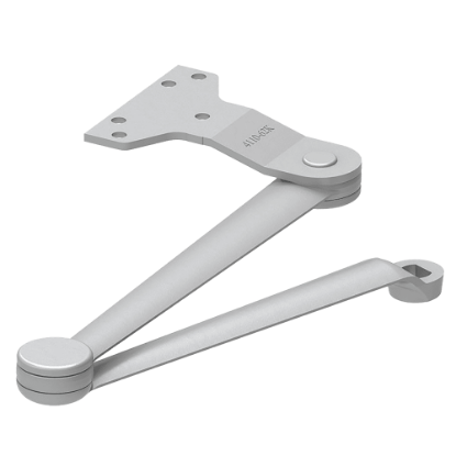
LCN 4210-3077EDA Extra Duty Arm, non-handed forged steel parallel arm for the LCN 4210 Smoothee high security closer

If a door stop is needed on an EDA arm installation, it must be a separate overhead stop or wall stop device, not a CUSH arm accessory. Using a separate stop device alongside a CUSH arm installation is redundant and not recommended.


What Is the LCN 4210 Cush Arm (CUSH-N-Stop)?

The 4210-3077CNS Cush Arm is an optional handed parallel arm with a built-in stop in the soffit shoe. CUSH stands for Cush-N-Stop. When the door reaches its templated maximum opening angle, the arm contacts the stop in the shoe and arrests the door without any separate stop device.
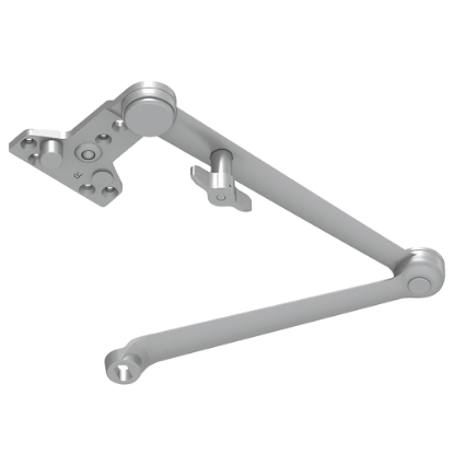
LCN 4210-3077CNS Cush Arm, handed forged steel parallel arm with built-in stop, for the LCN 4210 Smoothee high security closer

The Cush Arm is forged solid steel with a double slab arm-to-pinion attachment. It is handed and must be specified left-hand or right-hand at order. Templated maximum openings are available at 85 degrees (A = 8-5/16 in., B = 9-5/8 in.) and 90 degrees (A = 7-11/16 in., B = 9 in.).

The drop plate (4210-18) is required for all Cush Arm installations. The CUSH shoe support (4210-30) is required when the frame reveal is less than 3-1/16 inches. The fifth hole spacer (4210-201) works alongside the CUSH shoe support. Order all three at the same time to avoid installation delays.


What Is the LCN 4210 Hold Open Cush Arm?

The 4210-3049CNS Hold Open Cush Arm provides both a built-in stop and a hold-open function in a single arm. A handle on the arm controls when the hold-open is engaged. Two important restrictions apply: the Hold Open Cush Arm is not available with the 4216 cylinder, and the Delayed Action cylinder option is also not available with the 4216. Confirm the cylinder variant before ordering this arm.
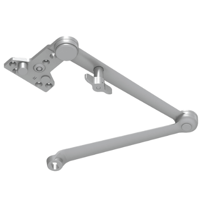
LCN 4210-3049CNS Hold Open Cush Arm, handed arm with built-in stop and hold-open, for the LCN 4210 Smoothee high security closer


What Is the LCN 4210T Standard Track Arm?

The 4210T-3077T Standard Track Arm is the arm used on the 4210T track variant. It is handed with a large cross-section forged steel arm. The high security feature is the threaded attachment between the arm and the track roller (4210T-3034). The roller threads into the arm for extra strength and cannot be removed without disconnecting the arm from the closer body. The roller is included when the 4210T-3077T arm is ordered separately.


Metal Security Cover: LCN 4210-72MC and 4210T-72MC

The metal security cover is a standard component of both the 4210 and 4210T and is one of the distinguishing features of the Smoothee series. It uses four-point mounting for extra tamper resistance compared to two-point mounting on standard LCN series covers. The cover is handed and must match the finish of the installed hardware.
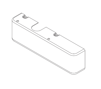
LCN 4210-72MC Metal Security Cover, four-point mount, handed, for the LCN 4210 Smoothee high security door closer

The 4210 uses the 4210-72MC and the 4210T uses the 4210T-72MC. These covers are different and cannot be substituted between the 4210 and 4210T. The cover is secured by the cover screw (4210-31 for the 4210, 4210T-31 for the 4210T).

An important service reminder: closer adjustments are not accessible with the cover installed. The cover must be fully removed before any regulation valve or spring adjustment. After service, reinstall the cover and confirm all four mounting points are secured with the correct cover screw.


Drop Plate, CUSH Shoe Support, Blade Stop Spacer, and Flush Panel Adaptor

Four accessories are required or optional depending on the frame conditions of the specific installation. These are frequently missed at order time and are among the most common causes of delayed installations.


When Is the LCN 4210-18 Drop Plate Required?
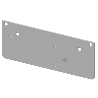
LCN 4210-18 Drop Plate for narrow top rail or flush ceiling installation on the LCN 4210 Smoothee high security closer

The 4210-18 Drop Plate has two trigger conditions.

  • The top rail is less than 5-1/8 inches measured from the stop on a push-side mount.
  • Any Cush Arm or Hold Open Cush Arm installation, regardless of top rail depth.

One dimension that every competitor misses: the plate requires a minimum top rail of 2 inches measured from the stop. If the top rail is less than 2 inches, the drop plate cannot be used. The plate ships with TORX screws. The 4210-18 is physically the same plate as the 4110-18, but the 4210-18 ships with TORX screws for high security mounting, while the 4110-18 does not. Do not substitute a 4110-18 on a 4210 installation.

The 4210T uses the 4210T-18 Drop Plate, triggered when the top rail is less than 5-1/4 inches, with a 2-1/4-inch minimum top rail required.


When Is the LCN 4210-30 CUSH Shoe Support Required?

The 4210-30 CUSH Shoe Support is needed when a Cush or Hold Open Cush Arm is installed and the frame reveal is less than 3-1/16 inches. The five-screw connection at the CUSH shoe is critical because the built-in stop generates significant force during the door arresting action. The CUSH shoe support provides anchorage for the fifth screw when the jamb depth is too shallow for a standard installation. Without it on shallow frames, the shoe will pull away from the frame under repeated use.


When Is the LCN 4210-419 Flush Panel Adaptor Needed?

The 4210-419 Flush Panel Adaptor is needed when the CUSH shoe must mount to a single rabbeted or flush frame that does not provide a horizontal mounting surface for the shoe. The adaptor creates the required horizontal surface.


When Is the LCN 4210-61 Blade Stop Spacer Needed?

The 4210-61 Blade Stop Spacer is needed when a 1/2-inch blade stop is installed in the frame. The spacer lowers the parallel arm shoe to clear the blade stop. Without it, the shoe contacts the blade stop before the door reaches its full intended opening angle.


What Does AVB Mean on the LCN 4210 Cylinder?

AVB stands for Advanced Variable Backcheck. It is an optional cylinder feature ordered with the suffix CYLAVB. On a standard LCN closer, backcheck begins at approximately 75 degrees of door opening, providing resistance against the door being forced or blown open. With AVB, backcheck starts at approximately 45 degrees, providing earlier and more pronounced resistance.

AVB is available on the 4210 series cylinder. It is useful in high-wind locations, on heavy-traffic openings where doors are routinely pushed open aggressively, or in any application where resistance at a lower opening angle reduces the risk of the door striking an adjacent wall or object. Specify CYLAVB when ordering the cylinder if AVB is required.


Can the LCN 4210 Hydraulic Fluid Be Refilled in the Field?

No. The hydraulic fluid in an LCN closer must not be refilled in the field. If a 4210 is showing signs of hydraulic fluid leakage, the appropriate response is closer replacement, not a fluid top-off. Attempting to refill the fluid voids the warranty and is explicitly stated as not permitted in LCN service guidance.

The all-weather hydraulic fluid in the 4210 performs without variation between -30 degrees F and +120 degrees F. This eliminates the need for seasonal closing speed adjustments that affect standard hydraulic closers. If a 4210 installation requires frequent speed adjustments as seasons change, the more likely cause is a seal or valve issue, not the fluid composition.


What Is the LCN 4210 Regulation Valve Adjustment Limit?

All LCN door closers have three regulating valves: General Speed (main closing speed), Latch Speed, and Backcheck. The 4210 follows this same three-valve design. LCN recommends not opening or adjusting the regulation valves more than 3 full turns from the shutoff position. Opening the valves beyond this limit can damage the seals and cause hydraulic fluid leaks. The regulation valve assemblies are staked to provide a physical warning when the screws approach maximum adjustment, but they do not mechanically prevent over-adjustment.

If the door does not latch after adjusting the latch speed valve, the solution is to increase spring power, not to open the latch speed valve further. Increasing the latch speed valve opening changes the closing rate but does not increase the closing force available for latching. Increasing closing force requires spring power adjustment on the Green Dial.

For step-by-step guidance on adjusting LCN door closer speed and spring settings, see the guide to adjusting a commercial door closer.


Does the LCN 4210 Require Periodic Maintenance?

Closers mounted according to LCN installation instructions require no periodic maintenance or seasonal adjustments. The all-weather hydraulic fluid handles the full operating temperature range without change to closing time. Monthly, quarterly, and annual visual inspections are recommended for Fire and Life Safety rated installations only. For those applications, inspection intervals should align with the applicable fire code schedule.

The practical implication for facilities maintenance staff is that a correctly installed 4210 in a standard application should not need routine service. If a 4210 on a routine installation is requiring frequent readjustment, that indicates an installation issue (incorrect spring size for the door weight, incorrect valve settings, damaged seal) rather than a normal maintenance need.


How Do I Read the LCN 4210 Date Code?

The LCN date code is a four-digit code found on the closer body. The first two digits indicate the week of manufacture and the last two digits indicate the year. A date code reading "2519" means the closer was manufactured in week 25 of 2019. This is useful when assessing whether a closer is within warranty, identifying when parts were last installed, or planning replacement schedules on a building's door hardware inventory.

Do not confuse the date code with manufacturing reference numbers such as "71" or "320G" that may appear stamped elsewhere on the cylinder assembly. Those numbers are internal references and cannot be used to order replacement parts.


Can a 4510T Track Be Converted to a 4210T Track?

Yes. The 4210T-3038 standard track and the 4510T-3038 track are physically the same track, with one difference: the 4510T includes a spacer bar that the 4210T does not use. To convert a 4510T installation to a 4210T, remove the spacer bar from the 4510T track and replace the metal cover with the handed 4210T-72MC cover in the correct finish. The 4210T and 4510T use different handed metal covers, so the cover cannot be reused from the 4510T. The 4210T-3034 track roller and the threaded arm attachment remain the same across both models.

This conversion is useful when an existing 4510T installation needs to change its mounting orientation from hinge pull-side to push-side parallel arm. The core cylinder and track can be retained; only the cover needs to change. Confirm the handing matches the new door swing before ordering the replacement cover.


LCN 4210 Screw Packs: TORX vs Thru-Bolt

The 4210 uses Torx machine screws as standard, not the SRT (Self Reaming and Tapping) screws used on most standard LCN closer families. Two screw pack options are available.

Part NumberNameWhen to Use
4210-TORXTORX Machine Screw PackStandard mounting without thru-bolting
4210-TBTRXThru-Bolt Wood-Machine Screw PackThru-bolt installations where additional fastening security is required


How Do I Order the Correct LCN 4210 Replacement Part?

Confirm each of the following before placing an order to avoid receiving a part that does not fit the installation.

Confirm Before OrderingApplies To
Model variant (4210 or 4210T)Arms, covers, drop plates, arm screws
Hand of the doorCylinder, metal cover, Cush Arm, HCUSH Arm, 4210T arm
Cylinder size and type (not 4216 for HCUSH or Delayed Action)Cylinder assembly; HCUSH arm compatibility
Finish codeMetal cover, cylinder
Top rail depth (trigger: less than 5-1/8 in.; minimum: 2 in. for 4210-18)Drop plate (4210-18 or 4210T-18)
Frame reveal depth (less than 3-1/16 in. triggers CUSH shoe support)4210-30 CUSH Shoe Support
Blade stop present in frame (1/2 in.)4210-61 Blade Stop Spacer
Frame type (rabbeted or flush, for CUSH shoe mounting)4210-419 Flush Panel Adaptor
AVB required (backcheck at 45 degrees instead of 75)Cylinder with CYLAVB suffix

View the full parts listing and diagrams at the LCN 4210 and 4510 Smoothee series parts page. Call 845-935-0301 for pre-order identification support or to confirm specifications before ordering.


Troubleshooting Common LCN 4210 Field Issues

SymptomCheck FirstParts to Inspect or Replace
Door does not latch on closingRemove cover, check spring power on Green Dial; do not open latch speed valve beyond 3 turns from shutoffCylinder assembly; arm screw (4210-159)
Hydraulic fluid leaking from closerDo not refill fluid in the field; assess whether closer requires replacement; check regulation valve was not over-adjustedCloser replacement if fluid is leaking
CUSH shoe pulling away from frameConfirm fifth screw was installed; check if frame reveal is less than 3-1/16 in. and CUSH shoe support is present4210-30 CUSH Shoe Support; 4210-201 Fifth Hole Spacer
Door opening angle less than expected with CUSH armConfirm template used (85 or 90 degrees); check for blade stop contact with shoe4210-61 Blade Stop Spacer
Track arm binding or noisy (4210T)Inspect track roller; confirm track is clean4210T-3034 Track Roller; 4210T-3038 Standard Track
Door slamming (closing too fast)Remove cover, adjust general speed valve no more than 3 turns from shutoff; confirm fluid is not leakingRegulation valve adjustment only; replace closer if fluid has leaked out
Cover difficult to reinstallConfirm correct handed cover for model; 4210-72MC and 4210T-72MC are different covers4210-72MC or 4210T-72MC Metal Cover


Where Is the LCN 4210 Typically Installed?

Understanding the typical application environments for the LCN 4210 helps clarify why specific parts and accessories matter on a service call. The 4210 and 4210T are not general-purpose commercial closers. They are specified for environments where standard commercial closer components would not hold up to the demands of the installation.


Correctional and Detention Facilities

The 4210 is designed specifically for correctional applications. The TORX fasteners prevent unauthorized removal of the arm and cover. The four-point metal cover mounting resists prying. The forged steel arm provides strength against deliberate abuse. In these environments, every part matters: a cover screw (4210-31) that is stripped or a CUSH shoe that has pulled away from the frame is a security gap, not just a maintenance issue.


Institutional and High-Traffic Openings

Schools, university buildings, hospitals, and government facilities specify the 4210 on openings with very high cycle counts and some vandalism risk. The 10-million-cycle test rating reflects this use case. In these environments, the track roller (4210T-3034) on 4210T installations is the component most likely to show wear first, followed by the arm screw (4210-159 or 4210T-159).


What Is the Maximum Door Weight for the LCN 4210?

The maximum recommended door weight for LCN manual closers is 225 pounds. For the 4210, cylinder sizes 1 through 6 cover interior doors up to 5 feet wide and exterior doors up to 4 feet wide (for sized cylinders). Non-sized cylinders adjust for interior doors up to 4.5 feet and exterior doors up to 3.5 feet. The size 1 (4211) cylinder meets ADA opening force requirements when set at 5 pounds. For the LCN door closer sizing guide, including which cylinder size to specify for a given door weight and width, see the LCN door closer sizing guide.


LCN 4210 vs LCN 4110: Key Differences

The 4210 and 4110 share a similar naming structure and several accessories use the same part body. But they serve different security levels and must not be treated as interchangeable.

  • The 4210 uses TORX fasteners as standard. The 4110 uses standard screws.
  • The 4210 metal cover uses four-point mounting. The 4110 uses two-point mounting.
  • The 4210-18 drop plate ships with TORX screws. The 4110-18 plate ships without them.
  • The 4210 cylinder is a heavier cast iron unit rated for correctional applications. The 4110 cylinder is a standard cast iron unit.
  • Arms are not interchangeable between the 4210 and 4110 series.

If an installation is marked 4110 but shows TORX fasteners and a four-point cover, verify the model number stamped near the pinion. A 4210 may have been substituted at install. Use the stamped model designation near the pinion as the authoritative source for part identification, not the original specification sheet or the cover appearance. This is especially common on retrofitted correctional openings where the original specification called for a 4110 but the installing contractor upgraded to the 4210 for the security cover. In those cases, ordering 4110 arms or a 4110 cylinder on a subsequent service call will result in parts that do not fit. Always verify at the pinion. The model number stamped on the body is the only reliable identification method for LCN high security closers. For the complete parts listing with diagram references showing which part attaches where on the closer body, use the series parts page to cross-reference visual diagrams against the stamped model number before placing any order. Diagram 1 shows the arm and cover components. Diagram 2 shows the cylinder and accessory positions. Having both open when ordering reduces the chance of ordering the wrong handed component or missing a required accessory.


How to Read the LCN 4210 Model Number

The model number stamped near the pinion follows a consistent pattern. The series designation (4210 or 4210T) is followed by a size digit (1 through 6) indicating the cylinder size. Common model number designations found on installed 4210 closers include:

  • 4211 or 4211T: Size 1 cylinder, adjustable from Size 1 to 5 (ADA opening force capable)
  • 4212 or 4212T: Size 2 cylinder
  • 4213 or 4213T: Size 3 cylinder
  • 4214 or 4214T: Size 4 cylinder
  • 4216 or 4216T: Size 6 cylinder (note: Hold Open Cush Arm and Delayed Action not available)

Cylinder suffixes such as DEL (Delayed Action), CYLAVB (Advanced Variable Backcheck), and handing codes (LH, RH) follow the size digit in the full model string. Always read the full model string from the closer body before ordering cylinder assemblies or confirming arm compatibility.

Security Parts has supplied genuine OEM commercial door hardware components to locksmiths, glaziers, facilities managers, contractors, and security integrators since 2001. All 29 LCN 4210 and 4210T Smoothee series replacement parts listed in this guide are stocked and available for individual order. Security Parts carries genuine OEM LCN components, ensuring that replacement parts match the original specifications for fit, finish, material, and security rating.

The LCN 4210 is a high security product where correct part identification matters considerably more than on standard commercial closer series. An incorrectly handed arm or cover on a correctional or institutional opening can compromise the security intent of the installation. A CUSH arm ordered without the required accessories (drop plate, CUSH shoe support, fifth hole spacer) will arrive on site incomplete, causing delays. Confirm the model number, hand, cylinder size, cylinder type, and finish from the installed hardware before placing any order. If the model label is unreadable, the handing is unclear, or the cylinder suffix is not visible, call 845-935-0301 for identification support before ordering any LCN 4210 part.

All LCN 4210 parts verified in this guide are linked directly to their live product pages at Security Parts. For the complete parts listing with diagram references, see the LCN 4210 and 4510 Smoothee series parts and diagrams page.


Related Resources at Security Parts

Blog|Security Parts

Blog|Security Parts

Blog|Security Parts