 Trusted Since 2001





Quick Answer
Installing an exit device on a commercial door requires four things done in the right order: confirm your device type and handing before touching the door, mount the chassis at the correct height (touchpad centerline between 34 and 48 inches above finished floor per ANSI A156.3), install the appropriate strike for your configuration (rim, surface vertical rod, or concealed vertical rod), and verify latch engagement and egress force before the door goes back into service.
The steps differ for each device type. Rim devices mount at one point; surface vertical rod (SVR) devices require top and bottom rod adjustment; concealed vertical rod (CVR) devices require factory-prepped door pockets. Start with this guide from the beginning so you are following the correct steps for your specific installation.
Before You Start: Identify Your Exit Device Configuration
The most expensive exit device installation mistake happens before the first hole is drilled: a contractor starts the wrong set of steps because they did not confirm the device type. Rim, SVR, and CVR devices share some installation principles but have completely different strikes, rods, and door prep requirements. Confirm your device type first.
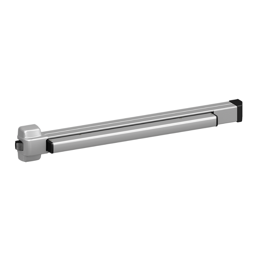
A rim exit device mounts to the door face and latches at one point. See the exit devices parts guide for component identification.
Rim Exit Device
A rim device mounts directly to the door face and latches at one point only. The strike mounts to the door frame. When the touchpad or crossbar is pushed, the latch retracts and the door swings free. Rim devices are the most common configuration and the simplest to install. Look for a single horizontal crossbar across the door width and a surface-mounted chassis on the door face. Common series identifiers: 98, 99, F-98, F-99, 22, 33A.
Surface Vertical Rod (SVR) Exit Device
A surface vertical rod device latches at two points: a top latch that engages the top frame and a bottom bolt that drops into a floor strike or threshold strike. The rods run vertically on the door face. SVR devices are used on doors without a center mullion or on pairs of doors where the active leaf requires multi-point latching. Look for exposed vertical rods running from the chassis to the top and bottom of the door. Common series identifiers: 9827, 9927, 27-series.
Concealed Vertical Rod (CVR) Exit Device
A concealed vertical rod device also latches at top and bottom, but the rods run inside the door cavity rather than on the surface. CVR installations require the door to have factory-prepped mortise pockets for the top latch assembly and a cutout for the bottom bolt. If the door does not arrive pre-prepped, field prep is significantly more involved. Look for a device with no visible rods on the door face. Common series identifiers: 9847, 9947, 47-series.
For help identifying which exit device series is installed or which series to order for a replacement, see the Von Duprin exit device series comparison and the Von Duprin panic bar selection guide.
What You Need: Tools and Materials Checklist
Required Tools
- Drill with bit set (1/4-inch and 3/8-inch bits for through-bolt applications)
- Tape measure
- 4-inch torpedo level or longer spirit level
- Pencil or punch awl for marking
- Phillips and flathead screwdrivers
- Allen/hex key set (for dogging slot and trim screws)
- Nut driver or adjustable wrench (for through-bolt nuts)
- Threadlocker compound (for through-bolt applications on hollow metal doors)
- Chisel (for CVR top latch pocket if door is not pre-prepped)
- Center punch (for accurate pilot hole placement on metal doors)
Materials to Have On Hand Before Starting
- Exit device with all included hardware (confirm nothing is missing before opening the door)
- Manufacturer installation template for the exact series being installed
- Correct strike for the device series (rim strike, top strike, bottom strike/floor box as applicable)
- Through-bolt kit if the door does not include it
- Backplate (required on thin hollow metal doors to prevent chassis deformation)
- For SVR: additional rod length if the door is taller than standard
- For CVR: edge prep kit if the top latch pocket is not factory-installed
Pre-Install Inspection Checklist
Running through this checklist before mounting prevents the two most common failed installations: wrong handing and a device that does not match the door prep. Both require sending the device back for exchange, which costs more time than checking takes.
Confirm the Handing
Stand inside the room facing the door from the secure side, meaning the side the door swings away from you. If the hinges are on your right, the door is right-hand (RHR or RH). If the hinges are on your left, the door is left-hand (LHR or LH). The handing of the exit device must match the door handing.
The handing designation is printed on the device carton label and on the chassis identification label inside the device. Confirm the carton label matches the door before opening packaging. Some exit device series are field-reversible by flipping the latch or lever trim; others are factory-handed and cannot be changed in the field. If the handing is wrong on a non-reversible device, do not mount it. Contact the supplier before proceeding.
Confirm the Door Prep
- Door width: Confirm the chassis length fits the door width. Most exit devices are available in standard widths (typically 36-inch and 48-inch door widths). A chassis that overhangs the door edge will not mount correctly.
- Door thickness: Through-bolt lengths and faceplate depths are door-thickness specific. Confirm the through-bolt length in the kit matches the actual door thickness before drilling.
- For CVR devices: Confirm the top latch mortise pocket dimensions and the bottom bolt cutout match the device specification. Measure the pocket depth, width, and location against the manufacturer template before mounting the chassis.
- For SVR devices: Confirm the rod lengths shipped with the device match the door height. Rods ship at maximum length and must be cut or adjusted down.
Inspect the Device Before Mounting
- Check the touchpad or crossbar for shipping damage (bent bar, cracked end cap, missing trim screws)
- Confirm latch projection by measuring from the latch face to the device faceplate. Standard latch projection is 5/8 inch. Confirm this matches the strike clearance on your frame.
- Verify that all rods, end caps, trim screws, through-bolts, and the installation template are in the packaging
- Confirm the included strike matches the device series. Strikes are series-specific and not interchangeable between device families
Exit Device Mounting Height Requirements
Mounting height is the most-searched specific installation question for exit devices, and the most common source of a code-noncompliant installation.
ANSI A156.3 Height Requirement
ANSI A156.3 requires the touchpad or crossbar centerline to be between 34 and 48 inches above the finished floor. This measurement is taken to the push element itself, not to the device chassis or the top of the touchbar. A device chassis mounted with its center at 38 inches may have a touchpad centerline at 36 inches, depending on the chassis design. Always measure to the push element after mounting, not to the chassis center.
The 34-to-48-inch range also satisfies ADA Section 404.2.7 for accessible door hardware. An exit device within this range does not require an additional accessible pull or lever on the push side.
Mounting Height Reference by Door Height
| Door Height | Recommended Chassis Mounting Center | Push Element Centerline Target |
|---|---|---|
| 7 ft (84 in) | 38--40 in from finished floor | 36--40 in (verify after mounting) |
| 8 ft (96 in) | 38--42 in from finished floor | 36--42 in (verify after mounting) |
| 9 ft (108 in) | 40--44 in from finished floor | 38--44 in (verify after mounting) |
| Any height | Adjust to keep push element within 34--48 in | 34--48 in (ANSI A156.3 absolute range) |
For ANSI and BHMA hardware standard context, see the ANSI/BHMA door hardware standards guide.
Marking the Mounting Height on the Door
Use the manufacturer installation template for your device series. Position the template at the target height with the push element centerline mark at the intended measurement. Confirm the template is level before marking any holes. Mark all hole center points with a pencil or punch awl before drilling. On metal doors, use a center punch to prevent bit walk when drilling.
Metal Door vs Wood Door Installation Differences
Hollow Metal Door Installation
Through-bolt mounting is required on hollow metal (HM) doors. The hollow interior of the door does not provide enough thread engagement for wood screws or short machine screws to resist the repeated lateral force applied to the exit device during daily egress cycles. Through-bolts pass completely through the door and are secured with nuts on the interior face.
- Use the through-bolt kit supplied with the device or ordered separately for the series
- A backplate on the interior door face is required on thin hollow metal doors (typically 14 gauge or thinner) to prevent the through-bolt nuts from pulling through the door face under load
- Apply threadlocker compound to through-bolt threads before tightening. Vibration from repeated door operation can loosen nuts over time without it
- Tighten nuts to the manufacturer-specified torque (typically 60--80 in-lb). Do not over-tighten, which can deform the chassis or door face
Wood Door Installation
Solid core wood doors can use the machine screws provided with the exit device in most cases. However, through-bolt mounting is still recommended on high-cycle openings or any door that will see heavy commercial traffic.
- Pilot holes should be drilled at 70--80% of the screw diameter to prevent splitting on solid wood doors
- Minimum door thickness for adequate thread engagement is typically 1-3/4 inches. Confirm the fastener length in the kit is appropriate for the actual door thickness
- On doors with veneer or laminate faces, over-tightening can crack or delaminate the surface. Tighten just until the chassis is firmly seated
Aluminum Storefront and Glass Doors
Exit devices on aluminum storefront frames require a device series specifically listed for that door and frame type. Standard exit device hardware is not designed for narrow stile aluminum extrusions. Glass doors with patch fittings require a device series compatible with the patch dimensions. Confirm the device series listing before ordering for any aluminum or glass door application.
How to Install a Rim Exit Device (Step by Step)
Rim installation is the most straightforward of the three device types. The device mounts to the door face with through-bolts, and the rim strike mounts to the door frame. For Von Duprin 98/99 series rim device components, see the Von Duprin 9899 series parts guide. For Falcon 19, 24, and 25 series rim devices, see the Falcon 19/24/25 series exit device parts guide.
Step 1: Prepare the Door and Apply the Template
Position the manufacturer installation template on the door face at the target mounting height. The template shows the hole pattern for the specific device series. Confirm the template is oriented correctly for the door handing (RHR or LHR). Use the template center marks to align the push element centerline at the intended height. Hold the template in position and mark all hole centers with a pencil. Confirm the level before marking.
Step 2: Drill Mounting Holes
On hollow metal doors, use a center punch at each marked location before drilling to prevent bit walk. Drill pilot holes for through-bolts using the bit diameter specified in the installation template (typically 1/4 inch for standard through-bolts). On wood doors, drill pilot holes at 70--80% of screw shank diameter. Clear all chips before proceeding.
Step 3: Mount the Chassis to the Door Face
Set the device chassis against the door face with all holes aligned. Insert through-bolts (or screws on wood doors) through the chassis and door. Start all fasteners before tightening any of them. Once all fasteners are started, tighten in a cross pattern to draw the chassis evenly against the door face without rocking. Apply threadlocker to through-bolt threads on metal doors before tightening the nuts.
Step 4: Install the Rim Strike on the Door Frame
Hold the door in the closed position and mark the strike location on the door frame by pressing the door gently against the frame and transferring the latch centerline. The rim strike must align with the latch both vertically and laterally. Fasten the strike to the frame with the provided fasteners. Most rim strikes have slotted holes for minor vertical adjustment.
Step 5: Set the Latch Projection and Strike Alignment
Close the door and observe how the latch enters the strike. The latch should enter cleanly and engage the strike keeper without rolling back or dragging on the strike lip. If the latch rolls back (does not engage), the strike is too far from the frame face. If the latch drags, the strike is too close or misaligned vertically. Adjust strike position as needed and re-fasten.
Step 6: Secure All Fasteners and Verify Operation
Fully tighten all through-bolt nuts and mounting screws. Operate the touchpad 10 times in succession and confirm the latch retracts fully and consistently each time. Confirm the door latches fully when closed without requiring any pressure on the door face. Proceed to the post-install testing checklist.
How to Install a Surface Vertical Rod (SVR) Exit Device (Step by Step)
SVR installation adds two additional steps to the rim process: top and bottom rod length adjustment. The rods ship at maximum length and must be shortened or adjusted to the actual door height. For Von Duprin 22-series, 33A, 35A, and 55-series SVR devices, see the Von Duprin 22/33A/35A/55 series exit device parts guide.
Step 1: Prepare the Door and Confirm Rod Lengths
Apply the installation template at the target mounting height and mark all chassis holes. Before drilling, hold the device against the door and extend the top rod toward the top frame and the bottom rod toward the floor. Confirm the rods reach their respective strikes with the device chassis at the target mounting position. If the door height is less than the maximum rod length, note the adjustment needed.
Step 2: Mount the Chassis to the Door
Follow Steps 1 through 3 from the rim installation procedure above. The chassis mounting process is identical. Confirm the chassis is level before fully tightening through-bolt nuts.
Step 3: Attach and Adjust the Top Rod Assembly
Connect the top rod to the chassis rod connection point. Run the rod toward the top of the door. Most SVR top rods have a threaded coupler at the strike end that allows length adjustment. Thread the coupler in or out until the top latch engages the top strike correctly when the touchpad is released. Confirm the top latch retracts fully when the touchpad is pressed.
Step 4: Attach and Adjust the Bottom Rod Assembly
Connect the bottom rod to the chassis and run it toward the floor. The bottom rod connects to the floor bolt, which drops into a floor strike or threshold strike. Adjust the rod length so the floor bolt drops cleanly into the floor strike and engages fully when the touchpad is released. The bottom bolt should retract fully when the touchpad is pressed. Confirm both rod connections are tight after adjustment.
Step 5: Install Top and Bottom Strikes
Install the top strike in the header frame at the height required to align with the top latch centerline. Install the floor strike (or threshold strike) at the floor position aligned with the bottom bolt centerline. Both strikes typically have slotted mounting holes for minor alignment adjustment.
Step 6: Set Rod Tension and Test Both Latch Points
Operate the touchpad and confirm both the top latch and the bottom bolt retract simultaneously and fully. Close the door and confirm both latch points engage their respective strikes cleanly. Adjust top or bottom rod length if either latch point drags, rolls back, or fails to engage fully.
How to Install a Concealed Vertical Rod (CVR) Exit Device (Step by Step)
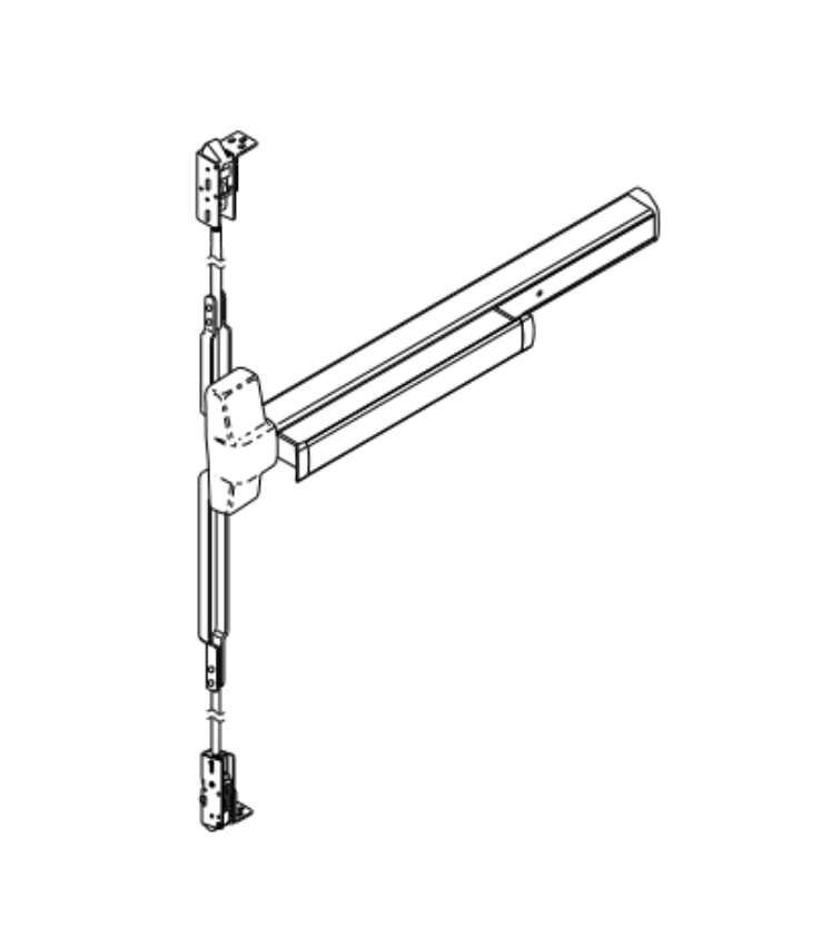
Von Duprin 98/9947 CVR exit device. Rods are concealed inside the door cavity. View product page. For all CVR replacement parts, see the Von Duprin 9947 CVR exit device parts guide.
CVR installation is the most complex of the three types because the rods run inside the door cavity and the door must be pre-prepped with specific pockets and cutouts. Do not attempt CVR installation on a door that has not been factory-prepped or field-prepped to the manufacturer's specifications.
Step 1: Confirm Door Prep (Top Latch Pocket and Bottom Bolt Cutout)
Measure the top latch mortise pocket (typically at the top of the door edge) against the manufacturer's dimension specifications. Confirm the pocket depth, width, and distance from the door top match the CVR device requirements. Measure the bottom bolt cutout at the door bottom edge and confirm it aligns with the floor strike location. If either prep dimension is incorrect, field modification is required before mounting the chassis.
Step 2: Mount the Chassis to the Door
Apply the installation template and mark all chassis mounting holes. Drill and mount the chassis using the same through-bolt process as rim and SVR installation. Confirm the chassis is level and fully seated before tightening.
Step 3: Route and Connect the Top Latch Assembly
Feed the top latch assembly up through the door cavity to the top latch pocket. Connect the top rod to the chassis drive mechanism and route it through the door interior. Seat the top latch housing in the top pocket and fasten it according to the manufacturer specification. Confirm the top latch retracts when the touchpad is pressed and extends fully when released.
Step 4: Route and Connect the Bottom Bolt Assembly
Feed the bottom bolt assembly down through the door cavity to the bottom cutout. Connect the bottom rod to the chassis drive and route it to the bottom bolt housing. Seat the bottom bolt housing in the bottom cutout and fasten it. Confirm the bottom bolt drops fully when the touchpad is released and retracts fully when the touchpad is pressed.
Step 5: Install Top and Bottom Strikes
Install the top strike in the header frame at the correct height for the top latch centerline. Install the floor strike aligned with the bottom bolt centerline. Both strikes must account for the latch projection depth of the CVR device, which may differ from the SVR projection depth on the same door configuration.
Step 6: Check Bolt Engagement and Adjust
Close the door and verify that both latching points engage cleanly. Cycle the touchpad 10 times and confirm both the top latch and bottom bolt retract and extend consistently. Adjust rod connections at the chassis if either bolt is not traveling the full stroke. Confirm all interior fasteners on the latch and bolt housings are tightened before final inspection.
Dogging the Exit Device After Installation
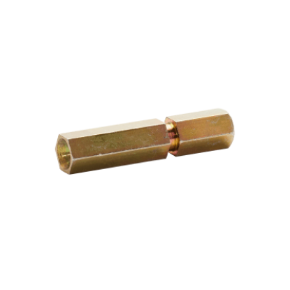
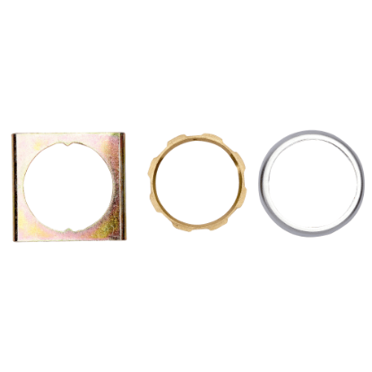
Left: Von Duprin 090040 hex dogging shaft. Right: Von Duprin 107813 cylinder dogging kit. Both are used for mechanical dogging on standard (non-fire-rated) openings.
Dogging holds the exit device latch in the fully retracted position so the door operates as a standard push-pull door without requiring touchpad pressure. It is typically engaged during business hours and released after closing. Dogging is set after installation, not before.
What Dogging Does
When the latch is dogged, the touchpad or crossbar is held in the depressed position mechanically. The door swings freely in both directions without any requirement to push the touchpad. This is the normal daytime operating mode for high-traffic openings that do not require controlled egress during business hours.
Mechanical (Hex Key) Dogging
The dogging slot is located on the face of the chassis near the touchpad connection. Insert a 3/32-inch hex (Allen) key into the dogging slot and turn it to lock the touchpad in the depressed position. The hex key is removed after dogging; the device stays dogged until the key is reinserted and turned to release.
Mechanical dogging is not permitted on fire-rated openings. A fire door must self-latch every time it closes, and mechanical dogging defeats that requirement. If a fire-rated opening needs free-swing daytime operation, electric dogging is the only compliant option.
Electric Dogging (QEL and MEL Options)
Electric dogging uses an internal solenoid to hold the latch retracted under access control command. When power is cut or the fire alarm triggers, the solenoid releases and the device returns to full latching function. QEL (quiet electric latch retraction) and MEL (motor-driven electric latch retraction) are the two common electric dogging options. For the difference between the two and which to specify, see the Von Duprin QEL vs MEL guide and the access control and commercial door hardware integration guide.
Electric Strike Alignment for Exit Devices
When an exit device is paired with an electric strike for access control, the strike and the device latch must be aligned before the installation is complete. Misalignment is the most common cause of a latch that functions correctly under hand operation but fails to engage reliably under normal door operation. For electric strike replacement parts, see the electric strike parts guide.
Rim Device and Electric Strike Alignment
The rim strike cutout must align with the rim latch both laterally and vertically. With the door in the closed position, confirm that the latch centerline aligns with the center of the electric strike keeper opening. Most electric strikes have a small adjustment range within the frame pocket. Use this range to center the keeper on the latch before final fastening.
Vertical Rod Device and Electric Strike
On SVR and CVR installations, the electric strike typically electrifies only the top latch. The bottom bolt remains mechanical and always extends when the door closes. The top latch alignment process is the same as for a rim device: confirm the top latch centerline aligns with the electric strike keeper centerline before final fastening. The bottom floor strike is installed mechanically and does not require electrical connection.
Testing the Strike and Device Together
Before energizing the strike, confirm the latch enters the keeper cleanly under manual door operation. Then energize the strike and test the following: the touchpad releases the latch while the strike is energized (the latch must retract even though the strike is holding it); the door opens when power is cut (fail-safe) or when the touchpad is pressed while the strike is powered (fail-secure). See the how to install an electric strike guide for detailed wiring and alignment procedure.
Fire-Rated Door Exit Device Installation Requirements
Fire-rated openings carry additional installation rules that are not optional. A standard panic hardware installation that violates any of these requirements fails the fire door assembly certification. For the full fire door hardware context, see the commercial door fire rating guide.
Fire Exit Hardware vs Panic Hardware
Exit devices on fire-rated doors must be UL listed fire exit hardware. Standard panic hardware does not carry a fire listing and cannot be substituted. The UL fire listing label appears on the device chassis and on the packaging. It identifies the specific fire door assembly types the device is tested for. Confirm the device's fire listing before installing on any fire-rated opening. For guidance on when panic hardware is required and the distinction from fire exit hardware, see the panic hardware for commercial doors guide.
No Mechanical Dogging on Fire-Rated Openings
Mechanical dogging (hex key or thumbturn dogging) is not permitted on fire-rated openings. It prevents the device from self-latching when the door closes, which voids the fire rating of the assembly. The only compliant option for free-swing operation on a fire door is electric dogging (QEL or MEL), which releases automatically when power is cut or when a fire alarm signal is received.
Coordinator and Closer Requirements on Paired Fire Doors
Fire-rated pairs of doors require a door coordinator that sequences the closing of the active and inactive leaves. Without a coordinator, the active leaf may close before the inactive leaf and prevent full latching. A door closer is also required on every fire-rated exit device opening. The closer must be listed for fire-rated assemblies and set to close and latch the door fully from any open position.
Post-Install Testing Checklist
Run through this checklist before considering the installation complete. Every item here reflects either a code requirement or a common failure mode that is easier to catch now than after the door has been in service.
Functional Egress Test
- Apply egress force to the touchpad and confirm the latch retracts. Maximum actuating force is 15 pounds for standard devices (30 pounds for fire-rated devices) per ANSI A156.3
- Push the door open from the fully closed position and confirm it swings to full open without binding
- Release the touchpad and allow the door to close. Confirm it latches fully without requiring additional force on the door face
Latch Projection and Strike Engagement Check
- Measure the latch projection from the device faceplate face. Confirm it matches the specification (typically 5/8 inch)
- Observe the latch entering the strike from the side if possible. The latch tip should enter the keeper cleanly without rolling back on the strike lip
- Check for any rattle of the latch in the strike keeper. A rattle indicates insufficient keeper depth or a worn latch
Dogging Function Test
- Insert the hex key and dog the device. Confirm the touchpad stays in the depressed position without the hex key
- Operate the door as push-pull and confirm it swings freely in both directions
- Insert the hex key and release the dogging. Confirm the latch returns to the extended position and the touchpad operates normally
Electric Strike Test (If Applicable)
- Fail-safe: cut power to the strike and confirm the door opens freely
- Fail-secure: restore power and confirm the door holds when pulled from outside
- Exit release: with the strike powered, push the touchpad and confirm the latch retracts and the door opens
- Confirm the strike solenoid does not buzz, click excessively, or produce heat above ambient after 60 seconds of operation
Fire Door Compliance Check (If Applicable)
- Confirm no hex key or mechanical dogging block is in place
- Open the door to 90 degrees and release it without assistance. Confirm the door closes fully and latches without any manual intervention
- Confirm the door coordinator sequences the leaves correctly on pairs (inactive closes before active)
- Confirm the door closer is set to pull the door to positive latch from any open position between 5 and 90 degrees
Common Exit Device Installation Mistakes
These are the installation errors that result in a callback, a failed inspection, or a code violation. Each one is preventable with the pre-install checklist above.
Installing the Wrong Handing
The device chassis is mounted upside-down or mirrored relative to the door handing. The touchpad ends up on the wrong side of the door, the latch points the wrong direction, or the trim does not align. Catch this during the pre-install handing check before any holes are drilled. If the device is not field-reversible, a factory exchange is the only resolution.
Measuring Mounting Height to the Chassis Instead of the Push Element
The ANSI A156.3 requirement is for the push element centerline, not the chassis center. A chassis center at 40 inches does not guarantee the touchbar centerline is at 40 inches. Measure to the touchpad or crossbar after mounting and confirm the push element is within the 34-to-48-inch range before final fastening.
Using Screw Mounting on a Hollow Metal Door
Short machine screws or wood screws in a hollow metal door do not have enough material engagement to resist repeated egress force. The screws pull out over time, the chassis loosens, and the device fails to function reliably. Through-bolt mounting with a backplate is required on all hollow metal door installations.
Using the Wrong Strike for the Device Series
Exit device strikes are series-specific. A strike from a different series may appear to fit physically but will have a different keeper depth or latch engagement geometry that causes latch rollback. Always confirm the strike part number matches the device series before ordering.
Skipping Rod Length Adjustment on SVR Devices
SVR rods ship at maximum length. Installing them without adjustment for the actual door height results in rods that bottom out before the chassis is fully seated, or rods that are too long and prevent the bottom bolt from dropping fully into the floor strike. Always measure and adjust rod length to the actual door height before mounting the chassis.
Mechanical Dogging on a Fire-Rated Opening
Applying mechanical dogging on a fire-rated exit device opening voids the fire door assembly certification and creates a life safety violation. If the opening requires free-swing daytime operation and carries a fire rating, order a device with QEL or MEL electric dogging before installation.
Omitting the Through-Bolt Nuts or Skipping Threadlocker
Through-bolts inserted without nuts, or nuts tightened without threadlocker on metal doors, loosen from vibration within weeks of installation. The chassis develops play, the latch alignment drifts, and the device requires reinstallation. Apply threadlocker before tightening all through-bolt nuts.
Troubleshooting Exit Device Installation Problems
For broader commercial door hardware troubleshooting guidance, see the commercial door hardware troubleshooting guide.
Touchpad Is Hard to Push
The most common cause is a chassis that is not seated flat against the door face. If the chassis is bowed or misaligned, the touchpad pivot binds against the chassis frame. Check that through-bolts are tightened evenly and that the chassis face is flush against the door. Over-tightened through-bolts can deform thin door faces and cause the same symptom; back off the nuts slightly and recheck.
Latch Does Not Engage the Strike When the Door Closes
Vertical or lateral misalignment between the latch and the strike keeper is the most likely cause. Mark the latch position on the strike face by applying chalk or crayon to the latch tip and closing the door once. The mark on the strike shows whether the latch is hitting above, below, or to the side of the keeper opening. Adjust the strike position accordingly.
Door Does Not Latch After Closing (SVR or CVR)
If the top or bottom latch point is not engaging after the door closes, the rod length is typically the problem. The rod may be too short (latch does not reach the strike) or too long (the rod is buckling before the latch fully extends). Adjust the threaded coupler at the rod connection point in small increments and retest after each adjustment.
Exit Device Rattles or Has Play After Mounting
Through-bolt nuts that are not fully tightened, or a backplate that is missing on a thin hollow metal door, are the two most common causes. Tighten all nuts to the specified torque and confirm the backplate is installed and seated. If play persists after tightening, inspect the chassis mounting holes for elongation, which indicates the door material has been overloaded and needs reinforcement.
Device Is Handed Incorrectly After Mounting
If the touchpad is on the correct side but the latch projects in the wrong direction, check the manufacturer documentation for field-reversibility. Some device series allow the latch to be reversed by repositioning a single component; others require a full exchange. Contact 845-935-0301 for part exchange support before disassembling the device chassis.
Maintenance After Installation
For a complete annual maintenance schedule for all commercial door hardware, see the commercial door hardware maintenance checklist.
Initial 30-Day Inspection
High-traffic doors should receive a 30-day check after installation. Re-check all through-bolt torque after the first month of use. On SVR devices, re-check rod length adjustment after the first month, since rod connection points can shift slightly during initial traffic cycles. Confirm latch engagement has not drifted from the initial setting.
Annual Inspection Points
- Touchpad pivot wear: apply slight lateral pressure to the touchpad. Any lateral movement beyond minimal play indicates pivot bushing wear
- Latch bolt engagement depth: confirm the latch still engages the strike keeper fully. A worn latch tip can reduce engagement depth over time
- Rod connection points (SVR and CVR): confirm rod couplers and connection fasteners are tight and rods have not shifted from adjusted length
- Strike alignment drift: recheck latch-to-strike alignment with the chalk test annually on high-cycle doors
- Dogging mechanism: confirm hex key dogging engages and releases without binding
- Egress force: retest actuating force with a pull scale and confirm it remains below 15 pounds (30 pounds on fire doors)
NFPA 80 Fire Door Inspection Requirements
NFPA 80 requires annual inspection and documentation for all fire-rated door assemblies, including the exit device, hinges, closer, and frame. The inspection must confirm self-latching function, correct device operation, absence of mechanical dogging, and that no components have been modified or replaced with non-listed parts. A written record of each inspection must be maintained.
Where to Source Exit Device Parts and Replacements
Security Parts stocks exit device parts across Von Duprin, Falcon, and other commercial hardware lines. For parts by device type, see the exit devices parts guide and the commercial exit device parts guide. For OEM versus aftermarket guidance before ordering replacement components, see the OEM vs aftermarket commercial door hardware guide.
Call 845-935-0301 for pre-order compatibility support when you need to confirm a part number against the installed device.
About the Author
This guide was written by the Security Parts team, a commercial door hardware specialist serving locksmiths, facilities managers, general contractors, and security integrators since 2001. Security Parts stocks exit device parts across Von Duprin, Falcon, and other commercial hardware lines, with same-day shipping on stocked components and pre-order compatibility support at 845-935-0301. For related installation guidance, see how to install a commercial door closer and commercial door hardware replacement and repair guide.