 Trusted Since 2001





This guide explains how to install a door closer on a commercial door from the first template mark to the final valve adjustment. It covers all three standard mounting positions, the manufacturer installation template, arm geometry, spring power setting, ADA compliance verification, and fire-rated door requirements. Every step applies to surface-mounted hydraulic closers, which handle the large majority of commercial door installations.
When you install a door closer on a commercial door correctly, it lasts through its rated cycle life. When installed incorrectly, it fails within months regardless of brand or quality. SecurityParts.com stocks LCN door closer parts and complete units for every commercial mounting configuration. Browse the LCN door closer parts catalog, the LCN commercial door closer selection guide, and the complete LCN brand parts catalog. Call 845-935-0301 or visit the SecurityParts.com contact page for pre-installation parts identification support.
How to Install Door Closer on Commercial Door: Key Facts Before You Begin
Installing a door closer on a commercial door correctly determines whether the device lasts through its full rated cycle life or fails within months. A commercial door closer is a hydraulic-mechanical device that controls the speed and force at which a door closes after being opened. Inside the housing, a compressed spring stores energy when the door opens. Hydraulic fluid flowing through calibrated passages governs how quickly the spring returns the door to the closed position. The result is a controlled, consistent closing arc on every cycle.
Incorrect installation of a door closer on a commercial door is one of the most common causes of premature closer failure, arm damage, and ADA non-compliance. A closer mounted in the wrong position, with the arm shoe set incorrectly, or with the wrong spring size for the door will not perform correctly regardless of how carefully the valves are adjusted afterward. Getting the physical mounting right from the start is what determines whether the closer lasts through its rated cycle life or fails prematurely.
For an overview of closer types including surface-mounted, overhead concealed, and floor spring models, see the commercial door closers types guide at SecurityParts.com before selecting the closer for your application.
Tools Required Before You Begin
Safety Precautions
- Never work alone on a heavy commercial door. A second person should control the door while you drill and mount hardware.
- On fire-rated doors, confirm with the authority having jurisdiction before beginning. Drilling non-approved holes can void the door's fire rating.
- Use a center punch on all metal door surfaces before drilling. Metal door faces deflect drill bits and produce misaligned holes.
- Do not over-torque the mounting screws. Stripped screws in hollow metal doors are a common and difficult problem to correct after installation.
- Keep the spring power dial or power adjustment at the factory default setting during initial installation. Set the final spring size only after the arm is attached and the door is cycling.
The Three Surface-Mounted Arm Configurations
Before touching the installation template, identify which arm configuration applies to your opening. The three configurations are not interchangeable, and using the wrong one changes which face of the door and frame the closer body mounts to, which side the arm shoe bracket goes on, and which template column to use.
Regular Arm
Closer body: Pull side of door
Arm extends to: Frame on pull side
Best for: Interior commercial doors, corridors, office doors
Profile: Arm projects outward from door face; highest visibility
Strength: Strongest closing force geometry
Parallel Arm
Closer body: Push side of door
Arm runs: Parallel to top of door when closed
Best for: Exterior commercial doors, high-security, vandal-prone openings
Profile: Low projection from door face; arm protected from vandalism
Strength: Slightly less mechanical advantage than regular arm
Top Jamb
Closer body: Frame head on push side
Arm connects to: Door top on pull side
Best for: Aluminum storefronts, narrow top-rail glass doors, frame-mount-only openings
Profile: Closer hidden at frame head; door face unmarked
Notes: May require soffit plate on aluminum extrusion frames
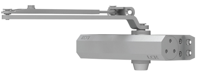
LCN 1000 Series surface mounted closers at SecurityParts.com available in regular arm, parallel arm, and top jamb configurations
Reading and Using the LCN Installation Template
The LCN installation template is a paper guide that ships inside the box with every new LCN closer. It is the most important tool in the installation process and the step that most field errors trace back to when skipped.
What the Template Shows
The template has separate columns for regular arm, parallel arm, and top jamb configurations. Each column shows the exact hole locations for both the closer body mounting holes and the arm shoe bracket holes relative to the door top edge and the door face. The template also shows the backset columns (the horizontal distance from the door edge to the latch bolt center) so the arm shoe is positioned correctly relative to the latch.
Step-by-Step Template Usage
Determine the correct template column Identify your arm configuration (regular, parallel, or top jamb). On the template, locate the column header for that configuration. If the door swings right (hinge on left), use the right-hand column. Left-swing doors use the left-hand column. Most LCN templates mark this clearly with an arrow and "Hinge Side" indicator.
Mark the centerline height on the door Most commercial installations place the closer centerline 1 inch from the door stop rabbet on the pull side. Measure from the top of the door down to this height and mark a horizontal line across the full door face with a pencil. This line is your alignment reference for the template.
Align the template fold line with the door top edge The template has a fold line or cut line that aligns with the top edge of the door. Fold the template along this line and position it so the fold sits at the door top edge and the template face lies flat against the door face. The centerline mark on the template should align with your pencil line.
Tape the template in place Use masking tape at all four corners. Verify the template has not shifted or bubbled before marking holes. A shifted template produces holes that are off by several millimeters, which changes the arm geometry at final installation.
Mark all hole centers with an awl or center punch On hollow metal doors, use a center punch and a single hammer tap to mark each hole center. This creates a small dimple that keeps the drill bit from walking across the metal surface. On wood doors, a sharp awl is sufficient. Mark every hole in the template before removing it.
Remove the template and drill all holes Use the correct bit size for the mounting screws supplied with the closer. For most LCN closers on hollow metal doors, this is a 7/32-inch bit. Drill straight through the door face only. Do not drill through the full door thickness unless instructed.
How to Install a Door Closer on a Commercial Door: Regular Arm
Regular arm is the most common configuration for interior commercial doors. The closer body mounts on the pull side of the door face, and the arm extends from the body to a shoe bracket mounted on the frame.
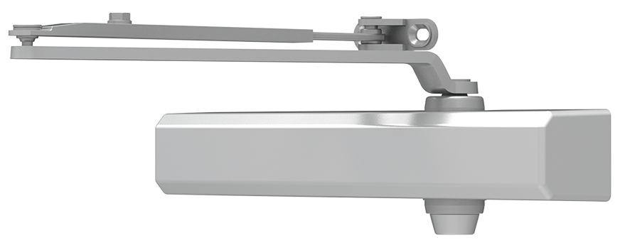
LCN 4000 Series surface mounted closers including the 4040XP at SecurityParts.com
Mount the closer body to the door face Position the closer body over the drilled holes on the pull side of the door. Insert the mounting screws by hand first to confirm alignment, then drive them with a screwdriver. Do not use an impact driver. The screw seats are in lightweight hollow metal and strip easily under impact torque. Snug is correct. The body should sit flat against the door face with no rocking.
Confirm the spindle is in the correct position On the LCN 4040XP, the closer spindle (the shaft that the arm attaches to) should point toward the hinge side of the door. Verify this before attaching the arm. If the spindle points toward the latch side, the closer was mounted in the wrong orientation and will bind through the closing arc.
Close and fully seat the backcheck valve Turn the B valve fully clockwise before attaching the arm. This prevents the door from swinging open without resistance during the next step.
Attach the main arm to the spindle Slide the main arm onto the closer spindle. The arm should engage the splined or keyed spindle shaft securely. Insert the pinch bolt and tighten finger-tight only. Do not fully tighten yet. You may need to rotate the arm slightly during the next step to align the shoe bracket holes.
Mount the shoe bracket on the frame Hold the door at 90 degrees open (have your second person hold the door). Position the shoe bracket on the frame at the hole locations marked by the template. Insert and drive the shoe bracket screws fully. Frame mounting screws go through the door stop into the hollow metal frame. Use all provided screws.
Connect the forearm to the shoe bracket With the door held at 90 degrees, connect the forearm end of the arm assembly to the shoe bracket. Insert the connecting pin or bolt, and tighten. Now tighten the pinch bolt at the spindle connection. The arm should feel rigid with no lateral play.
Test the arm through the full arc before valve adjustment Slowly open the door to full extension and allow it to close freely. Watch the arm through the full arc. The arm should move smoothly with no binding, scraping, or sharp changes in resistance (other than the backcheck engaging at approximately 70 to 75 degrees). If the arm binds at any point, stop and check the geometry before proceeding to valve adjustment.
How to Install a Door Closer: Parallel Arm Configuration
Parallel arm places the closer body on the push side of the door. The arm runs parallel to the door top rail when the door is closed, which keeps the arm below the sight line and reduces exposure to deliberate damage.
Mount the closer body on the push side of the door Drill holes per the parallel arm column of the template. Mount the closer body on the push face of the door with the spindle pointing toward the hinge side. On the parallel arm configuration, the body position is farther from the latch edge than on a regular arm installation, per the template dimensions.
Mount the parallel arm bracket on the frame push side The parallel arm uses a two-piece bracket system: a main bracket on the frame head and an adjustable shoe. Mount the frame bracket at the hole locations from the parallel arm column of the template. The bracket mounts on the frame push side at the same elevation as the closer body.
Confirm backcheck valve is closed Turn the B valve fully clockwise before attaching the arm.
Attach the arm to the spindle The parallel arm assembly is slightly different from the regular arm: the main arm attaches to the spindle and runs back toward the hinge side when the door is closed. Insert the spindle connector and snug the pinch bolt.
Connect the forearm to the frame bracket With the door held at 90 degrees, connect the forearm to the frame bracket through the shoe. Adjust the shoe position along the frame bracket slot so the arm is under slight tension in the closed position without being overtightened. Tighten the shoe set screw and the pinch bolt.
Verify arm does not contact the door stop when closing Slowly close the door from 90 degrees and watch the arm clearance as the door reaches the frame. The arm must not contact the door stop or frame extrusion at any point in the arc. If it does, adjust the shoe position slightly toward the hinge side and retest.
How to Install a Door Closer: Top Jamb Configuration
Top jamb is required on aluminum storefront doors and any opening where there is no accessible door surface on the pull side for closer body mounting. The body mounts on the frame head, not the door.
When a Soffit Plate Is Required
On aluminum extrusion frames, the frame head surface is often a narrow extrusion that does not provide a flat mounting surface matching the closer body hole pattern. A soffit plate (also called a mounting plate) attaches to the frame head first, distributing the closer mounting load across the extrusion. Without it, the mounting screws pull through the thin aluminum extrusion under the repeated load of each door cycle.
Check whether your frame head is a standard hollow metal section (minimum 1/16-inch wall thickness) or an aluminum extrusion. Aluminum extrusions almost always require a soffit plate. Hollow metal sections typically do not.
Mount the soffit plate if required If the frame head is an aluminum extrusion, mount the soffit plate to the frame head first using self-tapping screws into the extrusion at the template-specified locations. The soffit plate creates the flat mounting surface the closer body needs.
Mount the closer body to the frame head (or soffit plate) Position the closer body on the frame head per the top jamb column of the template. The spindle should point downward toward the door on the pull side. Drive all mounting screws fully. On hollow metal frames, these screws go through the frame head into the frame interior.
Mount the arm shoe bracket on the door top rail The arm shoe for top jamb mounts on the door top rail on the pull side. Drill per the template hole locations. Drive all shoe bracket screws fully into the door top rail.
Close the backcheck valve before arm attachment Turn the B valve fully clockwise.
Attach the arm assembly from spindle to shoe With the door held at 90 degrees, connect the arm from the closer spindle down to the door top rail shoe bracket. Insert the connecting hardware and tighten. The arm should be under slight tension with the door in the 90-degree open position.
Test the arm for clearance through the full arc Close the door slowly and confirm the arm clears all frame geometry through the full closing arc. Top jamb arms can contact the frame head stop if the arm is too long or the shoe position is too far from the hinge side.
Arm Adjustment After Mounting
Checking Arm Geometry
Before adjusting any valves, check that the arm geometry is correct. Open the door to 90 degrees and look at the arm from above. At 90 degrees, the main arm and the forearm should form approximately a 90-degree angle between them. If the arm is near-straight (less than a 90-degree angle between the two arm segments) at 90 degrees open, the shoe is too close to the hinge side. If the angle is very acute (more than 90 degrees), the shoe is too far from the hinge side.
Incorrect arm geometry at 90 degrees produces inconsistent closing behavior and accelerated wear at the arm pivot. The template dimensions prevent this when followed correctly. If the geometry is off, reposition the shoe bracket before proceeding.
Arm Connection Tightening Sequence
After geometry is confirmed correct, fully tighten all arm connections in this sequence: the shoe bracket screws in the frame or door first, then the forearm-to-shoe connection, then the pinch bolt at the spindle. This sequence prevents a loose frame bracket from causing the arm to shift during pinch bolt tightening.
Spring Power Adjustment
Spring power determines how much force the closer exerts to close the door. Too little spring power and the door stalls before latching. Too much and the door exceeds the ADA 5-pound opening force limit.
LCN 4040XP External Spring Power Adjustment
The LCN 4040XP uses an external spring power adjustment dial, also called the LCN Green Dial, on the spring tube. This allows spring power adjustment without removing the closer from the door or disassembling the unit. The dial has numbered positions from 1 (minimum) through 6 (maximum). To increase spring power, turn the dial clockwise. To reduce it, turn counterclockwise. Start at position 3 or 4 for a standard 3-foot interior door and adjust from there based on performance testing.
Spring Sizes on Other LCN Models
On LCN 1000 Series and other models without an external dial, spring power is determined by which spring the unit ships with. These closers come in sizes 1 through 6, and changing the spring size requires replacing the spring assembly inside the closer body. For most commercial door applications, ordering the closer in the correct spring size from the outset is more practical than field-swapping springs.
For specific parts for each LCN series including spring assemblies, arms, and mounting hardware, see the LCN 1000 Series door closer parts guide and the LCN 4000 Series door closer parts guide at SecurityParts.com.
Hydraulic Valve Adjustment After Installation
Once the arm is connected and the spring power is set, the three hydraulic valves need field adjustment to match the actual door conditions. All three valves are adjusted with a 3/32-inch hex key. Turn valves clockwise to restrict fluid flow and slow that phase of the closing arc. Turn counterclockwise to open flow and speed that phase up. Always make adjustments in 1/8-turn increments and test multiple cycles after each change.
Setting the Sweep Speed (S Valve)
The sweep valve controls the door from fully open down to approximately 10 to 15 degrees from the frame. Set the sweep speed first since it covers the longest portion of the closing arc. Target 5 to 7 seconds from 90 degrees to the point 3 inches from the frame on ADA-accessible doors. Time this with a stopwatch. If the door slams through the sweep arc, close the S valve clockwise. If it stalls before reaching the frame, open the S valve counterclockwise.
Setting the Latch Speed (L Valve)
The latch valve controls the final degrees from approximately 10 to 15 degrees to fully closed. Set it after the sweep is correct. The door should accelerate slightly through the latch zone and seat against the strike with a clean, firm click. If it stalls in the last few degrees or bounces back from the strike, open the L valve counterclockwise. If it slams into the frame, close it clockwise. The latch speed should always be slightly faster than the sweep speed.
Setting the Backcheck (B Valve)
Set the backcheck last. With the arm now connected and the door cycling correctly, slowly swing the door open past 75 degrees and feel for the resistance point. The backcheck should engage between 70 and 80 degrees and provide clear but not excessive resistance against the door being swung further open. If there is no resistance at all, close the B valve clockwise. If the backcheck engages too early (before 70 degrees) and makes the door feel stiff through the normal opening range, open it counterclockwise slightly.
For detailed valve adjustment guidance, seasonal calibration, and brand-specific instructions, see the complete commercial door closer adjustment guide at SecurityParts.com.
ADA Compliance After Installing a Door Closer on a Commercial Door
ADA compliance on door closers has two separate measurements that both must pass on accessible routes.
Opening Force: 5-Pound Maximum
Use a door pressure gauge at the leading edge of the door (the latch side). Push or pull perpendicular to the door face and read the peak force required to start the door moving. The limit is 5 pounds for interior non-fire-rated doors on accessible routes. If the reading exceeds 5 pounds, reduce spring power. Do not try to compensate with valve settings: valves do not control opening force.
Closing Speed: 5-Second Minimum
Using a stopwatch, time the door from 90 degrees open to the point 3 inches from the door stop. Per ANSI A117.1, the door must take a minimum of 5 seconds for this arc. If it closes faster, slow the sweep valve clockwise. A door that fails this test on an accessible route is an ADA liability regardless of how well everything else was done.
Fire-Rated Door Closer Installation Requirements
Installing a door closer on a fire-rated commercial door involves requirements beyond standard closer installation. Non-compliance is discovered during NFPA 80 annual fire door inspections and can result in immediate deficiency citations.
The Closer Must Be Grade 1 and UL Listed
ANSI/BHMA A156.4 Grade 1 is the minimum standard for fire-rated door assemblies. The closer must also carry a UL listing for fire door use. A Grade 1 closer without a UL fire listing is not an acceptable specification on a fire-rated opening, even though the grade rating alone might suggest otherwise.
No Hold-Open Arms on Fire-Rated Doors
NFPA 80 Section 4.7.1 prohibits any device that holds a fire door open in a manner that is not connected to the fire alarm system. A mechanical hold-open arm or a slide track arm with a hold-open feature cannot be installed on a fire-rated door. Every fire door must close and latch automatically after each use. The only compliant hold-open solution for fire-rated doors is a fire-rated electromagnetic holder that releases when the fire alarm activates.
Closing Speed Must Latch Against Fire Door Resistance
Fire doors are typically heavier than non-rated interior doors and include intumescent seals that compress as the door closes. The closer must have enough spring power and latch speed to overcome this seal compression and produce positive latching on every cycle. After installation, test the door from a full open position by releasing it without assisting the close. The door must self-close and self-latch without manual assistance.
For fire door closer adjustment guidance specific to NFPA 80 closing speed requirements and spring size selection, see the fire door closer adjustment guide at SecurityParts.com.
Common Door Closer Installation Mistakes
- Skipping the installation template The most common cause of incorrect arm geometry and premature arm failure. The template is not optional. It determines every hole position on both the door and the frame.
- Not closing the backcheck valve before attaching the arm Opening a door with the backcheck fully open and no arm resistance can damage the closer body on the first cycle. Always seat the B valve clockwise before connecting the arm.
- Mounting in the wrong arm configuration for the opening Installing a regular arm on a push-side application or a parallel arm on a pull-side opening reverses the mechanical advantage and produces incorrect geometry through the closing arc.
- Under-torquing the arm shoe bracket screws The shoe bracket takes the full mechanical load of every closing cycle. Insufficiently tightened screws work loose under repeated cycling and allow the bracket to shift, bending the forearm arm and eventually damaging the closer spindle.
- Using the wrong spring size for the door A spring too light for the door weight causes stall-before-latch. A spring too heavy produces opening force exceeding the ADA limit. Select the spring size by door width and weight, not by default to the closest spring on hand.
- Adjusting valves on a door with incorrect arm geometry Valve adjustment cannot compensate for incorrect mounting. If the arm geometry is wrong, no combination of valve settings produces consistent closing behavior. Fix the geometry before touching the valves.
- Installing a mechanical hold-open arm on a fire-rated door A direct NFPA 80 violation that will be cited on the next fire door inspection. Fire-rated doors must close and latch automatically on every cycle.
- Skipping ADA verification after installation Installation is not complete until opening force and closing speed are measured with calibrated tools. Estimated compliance is not compliance.
Troubleshooting After Installation
- Door stalls before latchingOpen the L valve counterclockwise in 1/8-turn increments. If the door still stalls, increase spring power one size. Check that the strike and latch bolt are aligned before adjusting further.
- Door slams into the frameClose the L valve clockwise to slow the final arc. If slamming happens through the main arc, also close the S valve. Confirm spring size is not too large for the door.
- Arm binds or feels stiff at a point in the arcStop immediately. A binding arm almost always indicates incorrect geometry. Check that the shoe bracket is at the correct template position. A binding arm puts destructive lateral load on the closer spindle.
- Opening force exceeds 5 pounds for ADAReduce spring power. Valve settings do not change opening force. On LCN 4040XP, reduce the spring power dial setting. On other models, replace with a smaller spring.
- Door closes too slowly for fire door latchingOpen the L valve counterclockwise. Increase spring size if the door still cannot overcome seal compression. Verify the arm geometry is correct and the arm is not binding.
- Closer body rocks or is not flush against doorHoles may be misaligned due to template not being held flat. Remove the closer and verify hole positions against the template. Re-drill if necessary using a longer drill guide.
- Arm shoe bracket loosens after a few daysAll frame screws were not driven fully. Remove the arm, re-drive all shoe bracket screws to full torque, and reattach the arm. Use thread-locking compound on the bracket screws if the holes are in a hollow section with minimal thread engagement.
- Door does not pull completely closed in cold weatherCold hydraulic fluid thickens and slows the closing arc. Seasonal valve adjustment is normal. Open the S and L valves slightly counterclockwise. If the closer uses standard (non-all-weather) hydraulic fluid, consider replacing the unit with an all-weather fluid model for exterior or temperature-exposed applications.
For broader door hardware troubleshooting beyond the closer itself, see the commercial door hardware troubleshooting guide at SecurityParts.com.
Maintenance After Installing a Door Closer on a Commercial Door
A correctly installed and adjusted commercial door closer requires minimal maintenance but does need periodic attention to stay in compliance and perform consistently.
- Inspect the arm connections and shoe bracket screws at every scheduled maintenance visit. Tighten any screws that show movement. On high-traffic doors, this should happen quarterly.
- Check closing speed with a stopwatch at the start of heating season and cooling season. Seasonal temperature changes affect hydraulic fluid viscosity and will shift valve performance. A few minutes of valve adjustment twice a year keeps the closer in spec.
- Inspect the arm pivot pins for wear. A worn or loose pivot pin produces arm rattle and changes the arm geometry subtly over time. Replace worn pivot hardware before the geometry shift damages the closer spindle.
- On exterior and vestibule closers, verify the cover plate is fully seated and undamaged. A missing or cracked cover exposes the valve ports to debris and water on exterior applications.
- Confirm ADA compliance measurements annually during fire door inspections and whenever the closer has been adjusted or the door has been re-hung.
For a complete maintenance schedule with monthly, quarterly, and annual task breakdowns, see the commercial door hardware maintenance checklist at SecurityParts.com. For door closer component identification, see the door closer parts diagram.
Why Choose SecurityParts.com for LCN Door Closer Parts
SecurityParts.com has supplied commercial door hardware parts since 2001. The LCN door closer catalog at SecurityParts.com covers the complete range including the 1000 Series, 4000 Series (4040XP), 3030/3130 overhead concealed, 2010/5010, 2210 high-security, and Sentronic electrified closers. Every model page includes an interactive parts diagram so you can identify the exact arm, shoe, bracket, spring, or cover plate needed before placing an order.
Browse the LCN 1000 Series surface mounted closer parts, the LCN 4000 Series surface mounted closer parts, the LCN 1000 Series parts guide, and the LCN 4000 Series parts guide. Browse the complete LCN door closer parts catalog and all SecurityParts.com commercial door hardware parts. Call 845-935-0301 or visit the SecurityParts.com contact page for pre-installation parts identification and same-day shipping support.
This guide on how to install door closer on commercial door is maintained by the commercial door hardware team at SecurityParts.com. For LCN door closer parts identification and same-day shipping support, call 845-935-0301 or browse the LCN door closer parts catalog.