RSS

Blog posts of '2026' 'July'

Master Key System Design Guide: Levels of Keying, Schlage Everest 29, SFIC vs FSIC and Construction Keying

A master key system is a hierarchy of keys where lower-level keys (change keys) each open one lock and higher-level keys (master, grand master) open progressively more locks. Standard commercial systems use 2 to 3 levels. Cross keying should be avoided wherever possible because it generates phantom keys and reduces system expansion capacity. Schlage Everest 29 offers three keyway families: R (restricted, tightly controlled), S (non-restricted, freely available), and T (restricted). SFIC (Small Format Interchangeable Core) allows fast rekeying in approximately 10 seconds without disassembling the lock. FSIC (Full Size Interchangeable Core) provides the same fast-rekey benefit in a full-size format specific to Schlage. Construction keying uses temporary cores keyed to a construction master key so all construction personnel can access the building; permanent cores are installed at project completion.

A well-designed master key system gives a building owner or facility manager exactly the access they need and nothing more, at every level from individual occupants up to the facilities director. A poorly designed one creates security vulnerabilities that are invisible until someone is harmed, compromises investigation in a theft or incident, and makes future expansion so difficult that the whole system has to be replaced. The design decisions made before the first cylinder is ordered determine whether the system stays secure for 20 years or creates problems within 5.

Browse Schlage key system products at SecurityParts.com: Schlage commercial hardware and key systems catalog, Schlage ND Series cylindrical locks for master keyed systems, Schlage L Series mortise locks for master keyed systems, and the complete Allegion hardware and key system parts catalog.

2029 Year Schlage Everest 29 patent protection on the undercut key design expires (introduced August 2012)
Cross key = avoid Cross keying generates phantom keys, reduces available differs, and should be avoided in every system design
10 sec Approximate time to rekey a lock with SFIC interchangeable cores using a control key; no disassembly needed
Simpler The simplest key system that meets the facility's access needs is the most secure and the most expandable


The Key Hierarchy: From Change Key to Great Grand Master

Every master key system is built on the same core principle: multiple keys of different access levels can all operate the same lock, but each lower-level key can only operate its own lock. The lock owner carries a change key. The floor supervisor carries a master key that also opens the same lock. The building manager carries a grand master key that opens every lock in the building. Understanding this hierarchy is the foundation of every design decision.


Level 4 (if needed)

Great Grand Master Key (GGM)

Opens all locks in all systems under it. Campus-wide, multi-building, or large complex systems. Reserved for the highest-level facilities authority. Should be strictly limited: typically one or two physical keys in existence.


Level 3

Grand Master Key (GMK)

Opens all locks under all master keys within a building or zone. Issued to building managers, facilities directors, and security directors. In a campus system, each building may have its own grand master key that operates under the great grand master.


Level 2

Master Key (MK)

Opens all change key locks within a defined group or section. Issued to department supervisors, floor managers, or maintenance leads who need access to all doors within their area but not the entire building. Each master key group should correspond to a defined organizational unit.


Optional Sub-Level

Sub-Master Key

Opens a subset of the change keys within a master key group. Used in larger systems where a section supervisor needs more than a change key but less than a full master key. Adds a level within a master group rather than between master groups.


Level 1 (lowest)

Change Key (CK)

Opens only one specific lock or a group of locks keyed alike. The key issued to an individual occupant, employee, or tenant. Losing a change key only compromises the locks that change key operates: rekeying is limited to those specific cylinders. Most keys in circulation in any system are change keys.


The Security Principle Behind Key Hierarchy Design

The security of a master key system is determined by the breadth of access that lost or stolen keys provide. A lost change key compromises one lock. A lost master key compromises an entire group. A lost grand master key compromises the building. This hierarchy means the number of keys at higher levels should be strictly minimized: the fewer grand master keys exist, the less the security consequence of a single key loss. Most well-designed commercial systems should have no more than 2 to 3 physical grand master keys in existence, with controlled issuance records for each.


Cross Keying: Why the Industry Recommends Against It

Cross keying is the deliberate process of combinating a cylinder to operate with two or more key bittings that would not normally be expected to operate it. The classic example: a janitor's key is cross keyed into every restroom on the floor, so the janitor can open all restrooms with one key even though those restrooms are on different sections of the master key system with different change keys.


Why Cross Keying Creates Problems

Every pin stack in a cylinder has a finite number of pin positions. In a standard master keyed cylinder, those positions are used to accommodate the change key bitting and the master key bitting. Cross keying requires the pin stack to also accommodate a third (or fourth) key bitting. This uses additional pin segment positions, which consumes the available differs in the system more rapidly.

The deeper problem is phantom keys. When a cylinder is cross keyed to operate with key A, key B, and master key M, the combination of pin segments required can accidentally create a fourth bitting combination C that was never intentionally cut but can also open the lock. This phantom key may correspond to a key that exists somewhere else in the system, creating an unintended cross-connection that violates the original access control design without anyone's knowledge.


The phantom key problem that no one knows about until the security incident: Phantom keys are unintentional. Neither the system designer nor the cylinder manufacturer knows a phantom key exists until someone discovers that an unexpected key opens an unexpected lock. In a healthcare facility, this could mean a patient room key also opens a medication room. In a school, it could mean a student key opens a teacher's office. Phantom keys are more likely in heavily cross-keyed systems and in systems that have been expanded without careful tracking of the available differs. The only reliable prevention is avoiding cross keying wherever possible and, when it must be used, having the key system designed by an experienced locksmith or manufacturer representative who can track the bitting assignments.
 

Alternatives to Cross Keying

Rather than cross keying a janitor into every restroom, consider keying all restrooms alike under a shared sub-master key. All restrooms then respond to one change key (the janitor's key) and to all master keys above it. This achieves the same operational result without the security compromise of cross keying, and without using up available differs.


Planning a Master Key System: Expansion Parameters and the Simplicity Rule

The most common master key system design mistake is building the smallest system the building currently needs without planning for expansion. A key system that works perfectly for 50 doors today may run out of available combinations when the facility adds 30 more doors in three years, forcing a complete replacement.


Define Expansion Parameters Before Ordering

Before specifying the first cylinder, define realistic expansion parameters in writing: the maximum number of change keys the system will ever need, the maximum number of master key groups, and the maximum number of levels. These numbers determine which key series and how many pins are required. Over-estimating is better than under-estimating: a system designed for 200 change keys that only uses 80 is fine. A system designed for 80 that needs 200 requires complete replacement.


The Simplicity Rule

The ASSA ABLOY master key system design guide states this directly: the simplest keying systems are often the most secure and will last longer than complicated ones. Every additional level of keying and every cross-keyed cylinder adds combinations to the system, uses up available differs faster, and increases the probability of phantom key generation. A 2-level system with no cross keying serving a 100-door building is more secure and more expandable than a 4-level cross-keyed system serving the same building.


The construction keying exclusion that many designers forget when specifying expansion: Construction cores use a specific set of bitting combinations to key all construction cylinders alike. Those construction bittings occupy a portion of the available differs in the key system. If construction keying is specified and the permanent system is planned to use all available bitting combinations, the construction bittings and the permanent change key bittings may conflict. When defining expansion parameters, exclude the construction keying bitting range from the permanent system's change key assignments to prevent any construction key bitting from accidentally matching a permanent key.
 

Schlage Everest 29 Keyway Families

Schlage introduced the Everest 29 keyway family in August 2012. The defining characteristic of all Everest 29 keyways is an undercut key design protected by patents until 2029. The undercut creates an additional area on the key blade that must align with a check pin in the cylinder for the key to operate. Keys without the correct undercut profile cannot turn the cylinder even if the pin heights are correct, providing an additional layer of physical security beyond standard pin tumbler bitting.


FamilyRestriction LevelKey DuplicationPatent StatusAvailable FormatsUse Case
Everest 29 RRestrictedFactory-controlled only; requires ordering authorization at restrictedproduct.allegion.comProtected until 2029SFIC, conventional, FSIC (via SL cylinder)Highest key control requirement: schools, hospitals, government, multi-tenant buildings
Everest 29 SNon-RestrictedAvailable from standard distributors; locksmiths can cut keysPatented but openly availableConventional, FSICPhysical security benefit of check pin without administrative key control burden
Everest 29 TRestrictedFactory-controlled; requires ordering formalitiesProtected until 2029Conventional, FSICRestricted key control similar to R family; FSIC format availability


Backward Compatibility with Older Everest Families

Everest 29 R keyways are backward compatible with Everest B keyways. Everest 29 S keyways are backward compatible with Everest C keyways. Everest 29 T keyways are backward compatible with Everest D keyways. This backward compatibility means a facility with existing Everest B or C cylinders can upgrade to Everest 29 cylinders and continue using existing Everest keys during the transition period, without requiring an immediate complete key change. New Everest 29 keys will operate both old Everest and new Everest 29 cylinders.


Primus XP Upgrade Path

The R and T restricted keyway families can be upgraded to Primus XP, which adds a second independent sidebar and finger pin locking mechanism to the cylinder. Primus XP provides both administrative key control (restricted keyway) and physical security (pick and drill resistance tested to UL 437). Primus XP is available in five levels of geographic exclusivity, from regional to national, allowing the facility to ensure no other building within a defined geographic area uses the same key section. Browse Schlage Primus and Everest 29 cylinder products at Security Parts.


Conventional Cylinders vs SFIC vs FSIC: Which Format to Choose


Conventional Cylinder

Key-in-lever, mortise, rim; fixed in housing

The standard cylinder format: the cylinder is fixed in the lock body and cannot be removed without disassembling the lock. Rekeying requires removing the cylinder, disassembling it, changing the pin stack, and reassembling.


Best for: Stable environments where rekeying frequency is low. Lower upfront cost than IC formats. Available for virtually every lock type and function.


Rekeying time: 15 to 30 minutes per cylinder, requires tools and cylinder removal.


SFIC (Small Format IC)

6- and 7-pin; cross-brand compatible

A removable core approximately 3/4 inch diameter. The control key rotates 15 degrees to release the core from the housing. The core can be removed and replaced in approximately 10 seconds without opening the door or removing the lock body.


Best for: High-turnover environments (universities, hotels, hospitals), large campuses where rapid rekeying is operationally critical, and facilities where the benefit of instant rekeying justifies the higher core cost.


Cross-brand compatibility: Schlage SFIC cores fit housings from multiple manufacturers. Best A2-format cores are cross-compatible with Schlage SFIC housings.


Rekeying time: Approximately 10 seconds with control key; no tools needed.


FSIC (Full Size IC)

Schlage-specific; full key system capability

A full-size removable core in the standard cylinder diameter. Like SFIC, it uses a control key to remove the core from the housing without disassembling the lock. Unlike SFIC, FSIC is manufacturer-specific: Schlage FSIC cores fit Schlage FSIC housings but are not cross-compatible with FSIC formats from other manufacturers.


Best for: Facilities already committed to Schlage hardware that want the fast-rekey benefit of interchangeable cores with the full capabilities of a Schlage master key system. The Schlage FSIC enables the complete range of Schlage keying options including Primus and Everest 29 keyways.


Rekeying time: Approximately 10 seconds with control key; no tools needed.


The Schlage Everest 29 SL: Unifying Three Formats Under One Key System

The Schlage Everest 29 SL cylinder solves a specific problem faced by large facilities with a mix of conventional, SFIC, and FSIC hardware: each format historically required its own separate key system. The SL cylinder uses an internal L-pin design that allows it to accept SFIC-format A2 keying (7-pin Everest 29 R keyways) while being housed in either a conventional key-in-lever cylinder or an FSIC format. This allows all three cylinder formats to share a single restricted key system under one set of master key bittings.

The SL cylinder is particularly valuable for campuses or large facilities that have accumulated a mix of cylinder formats over time and need to bring them all under a single restricted key system without replacing all installed lock hardware. Browse Schlage Everest 29 SL cylinder and key system products at SecurityParts.


Construction Keying: How Temporary Access Works During Building Projects

Construction keying is the standard practice for controlling access during new construction and major renovation projects. It allows construction personnel to use a single construction master key for all doors during the project without compromising the permanent key system.


1

Construction cores installed at hardware delivery

All locks in the project are delivered with construction cores installed. These cores are all keyed to the same construction master key bitting, so all workers can access all areas with one construction key.


2

Construction master keys issued to authorized workers

General contractor, subcontractors, and inspectors receive construction keys. Because all construction cores are keyed alike, a single key type provides access to the entire project. Key control is managed by the general contractor during the project.


3

Substantial completion: permanent cores installed

At substantial completion and transfer of ownership, the permanent operating cores (configured with the permanent master key system: change keys, master keys, grand master keys) are installed in place of the construction cores. The permanent key system is delivered to the building owner at this time.


4

Construction cores disposed of or returned

Disposable construction cores are destroyed after removal. Refundable construction cores are returned to the manufacturer or distributor for credit toward future orders. All construction keys should be collected and destroyed at this stage: any outstanding construction keys can no longer access the building once permanent cores are installed.


The construction keying bitting exclusion that prevents accidental key conflicts: Construction cores are keyed to specific bitting combinations that remain consistent across the construction industry within a manufacturer's key system. If those bitting combinations are not explicitly excluded from the permanent key system's change key assignments, the permanent key system designer may accidentally assign a permanent change key the same bitting as the construction key. This would mean a permanent employee's change key also opens the construction core in any lock where the permanent core was not installed or where a construction core was accidentally left in place. Always request that the key system designer explicitly exclude construction key bittings from the permanent system's change key range.


Key Control: Administrative Practices That Maintain System Integrity


Key Record and Issuance Log

Every key issued in a master key system should be logged with the recipient's name, date, key number, and level. Keys should be numbered with unique serial or identification numbers that cannot be removed or obliterated without visible damage. Signed receipts for each key create accountability. The log should identify which bitting each key number corresponds to, so the security consequence of a lost key can be immediately assessed.


Lost Key Protocol

When a key is lost, the response should be proportional to the key's level. A lost change key requires rekeying only the locks that change key opens. A lost master key requires rekeying all change key locks in that master key group. A lost grand master key requires rekeying all locks in the building. The key issuance log is the document that makes this assessment possible: without it, the scope of required rekeying cannot be determined with confidence.


Restricted Keyway Ordering Authorization

For restricted keyway systems (Schlage Everest 29 R or T families), additional key cutting or cylinder orders require authorization through Allegion's restricted product ordering portal at restrictedproduct.allegion.com. Maintaining an active authorized purchaser account in this system ensures that only the facility's authorized representative can order additional keys or cylinders in the restricted keyway. If the facility changes ownership or the authorized contact leaves, updating the authorization record promptly is essential to maintaining key control.

For key system ordering and cylinder parts support at SecurityParts.com, browse Schlage ND Series cylinders and key system components and Schlage L Series mortise lock cylinders. Contact the SecurityParts.com team at 845-935-0301 or the SecurityParts.com contact page for key system specification support.


Why Choose Security Parts for Schlage Key System Parts

Phantom key generation from cross keying documented, construction bitting exclusion requirement, Everest 29 backward compatibility detail, SL unified system concept, and same-day OEM shipping.


Phantom Key Documentation

We document the phantom key generation mechanism from cross keying and why phantom keys create unintended security connections that are invisible until a security incident occurs. This is absent from all competitor parts and key system content.


Construction Bitting Exclusion

We document the construction keying bitting conflict risk: if construction key bittings are not excluded from permanent system change key assignments, permanent employees may accidentally receive keys that also open construction cores. This is not documented by any competitor.


Everest 29 Backward Compatibility

We document the specific backward compatibility mapping (Everest 29 R to Everest B, S to C, T to D), enabling facilities to transition to Everest 29 gradually without immediate complete key change.


Same-Day OEM Shipping

Schlage Everest 29 cylinders, SFIC, and FSIC cores ship same day from US warehouses. Call 845-935-0301 or the contact page for key system specification support.


What Makes Security Parts Different for Key System Parts

  • We document the phantom key generation mechanism from cross keying. When a cylinder is cross keyed to multiple bittings, the additional pin segments can create accidental bitting combinations that open the lock unexpectedly. This security risk is mentioned by competitors but the mechanism is never explained. Understanding phantom keys prevents them during system design.
  • We document the construction keying bitting exclusion requirement. If construction key bittings are not excluded from the permanent system's change key range, a permanent change key may accidentally share a bitting with the construction master. This is a design-stage error that has zero visible consequence until a conflict is discovered.
  • We document the specific Everest 29 backward compatibility mapping by family (R to B, S to C, T to D), enabling phased transition from existing Everest installations to Everest 29 without complete key change. No competitor documents the family-to-family mapping explicitly.
  • We document the Everest 29 SL unified key system concept: a single restricted key system operating conventional, SFIC, and FSIC cylinder formats simultaneously using one set of master key bittings. This is the most complex Schlage key system feature and is not documented at the parts ordering level by any competitor.
  • We carry Schlage Everest 29 cylinders and key systems, Schlage ND Series lock cylinders, and Schlage L Series mortise lock cylinders for complete key system implementations from an authorized Allegion distributor.
  • Free shipping on orders over $450. Same-day shipping from US warehouses on stocked parts. 30-plus years of commercial door hardware experience.


Frequently Asked Questions About Master Key System Design


What are the levels of keying in a commercial master key system?

Level 1 (lowest) is the change key: opens only one lock or group of keyed-alike locks. Level 2 is the master key: opens all change key locks in a defined group. Level 3 is the grand master key: opens all master key groups in a building or zone. Level 4 (for large campuses) is the great grand master key: opens all grand master key groups across multiple buildings. Most commercial buildings use 2 to 3 levels. Adding more levels uses up available combinations faster and should only be done when the organizational structure genuinely requires it.


What is cross keying and why does it reduce master key system security?

Cross keying combinating a cylinder to operate with two or more different key bittings beyond its normal change key and master key. This uses additional pin segment positions, consumes available differs faster, and generates phantom keys: accidental bitting combinations that can open the lock when they were never intended to. Phantom keys create unintended security connections that are invisible until discovered in a security incident. Cross keying should be avoided wherever possible; keying similar doors alike under a sub-master key achieves the same operational convenience without the security compromise.


What is the difference between Schlage Everest 29 R, S, and T keyway families?

All three share the Everest 29 patent-protected undercut key design (protected until 2029). R (restricted): key distribution and duplication tightly controlled, requires ordering authorization from Allegion; highest administrative key control. S (non-restricted): patented but available from standard distributors; locksmiths can cut keys; check pin physical security without administrative restriction. T (restricted): similar administrative control to R family. R and T can both be upgraded to Primus XP for additional physical security. R, S, and T are backward compatible with existing Everest B, C, and D keyway families respectively.


What is the difference between SFIC and FSIC interchangeable cores?

SFIC (Small Format Interchangeable Core) is the industry-standard approximately 3/4-inch diameter removable core compatible with multiple manufacturers. Schlage SFIC is available in 6- and 7-pin lengths and is compatible with Best A2 housings. FSIC (Full Size Interchangeable Core) is a full-diameter removable core that is manufacturer-specific: Schlage FSIC cores fit Schlage FSIC housings but not competitor formats. Both rekey in approximately 10 seconds with a control key. SFIC is the choice when cross-brand compatibility matters; FSIC is the choice for maximum Schlage key system capability in a removable core.


What is construction keying and how does it work?

Construction keying uses temporary cores keyed to a single construction master key, giving all construction personnel access to all areas during the project without deploying the permanent key system. At substantial completion, the construction cores are replaced with permanent operating cores and the permanent key system is issued to the owner. Disposable construction cores are destroyed; refundable cores go back to the manufacturer for credit. All construction keys should be collected at ownership transfer since they can no longer access the building after permanent core installation.


What is the Schlage Everest 29 SL cylinder and when is it used?

The SL cylinder uses an L-pin design that accepts SFIC A2 7-pin keying in either a conventional key-in-lever or FSIC cylinder format. This allows three cylinder formats (conventional, SFIC, and FSIC) to share a single restricted Everest 29 R key system. It is used primarily to unify facilities that have a historical mix of cylinder formats under one restricted key system without replacing all installed lock hardware, and for campuses that need some doors as standard cylinders and others as SFIC for rapid rekeying, all on the same master key.
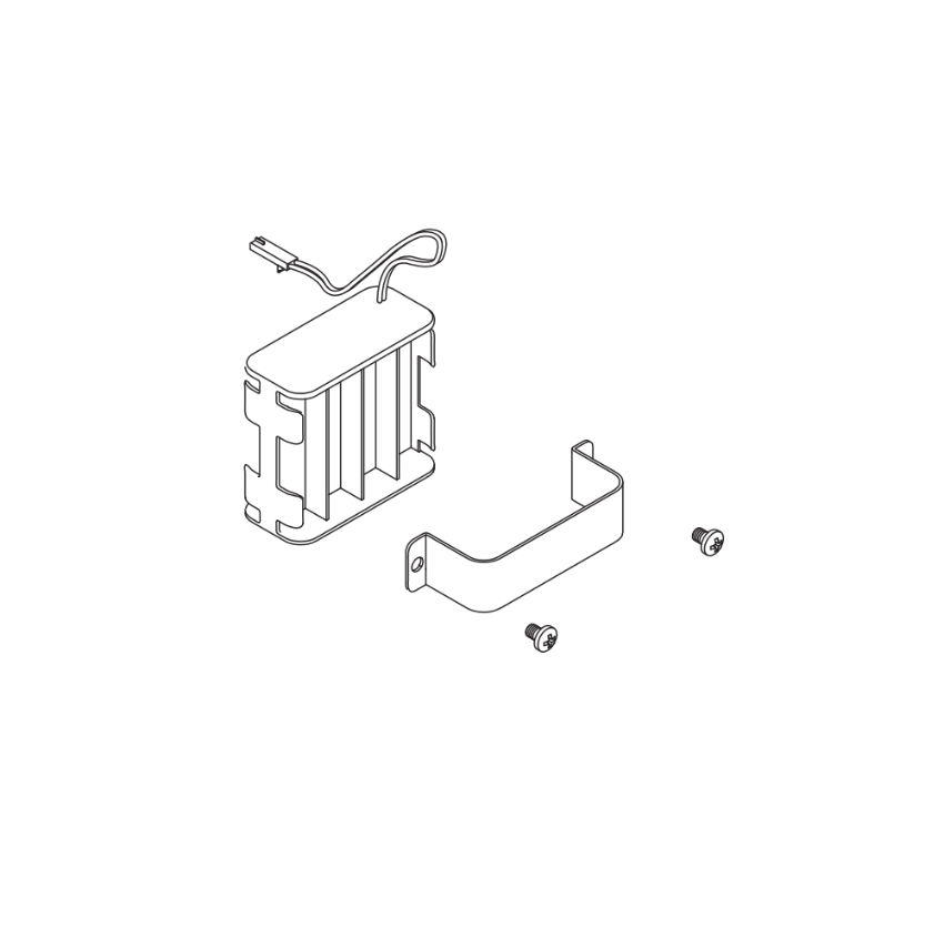
Schlage 46929063 4AA Battery Holder Kit: Complete Guide for AD and CO Series Locks

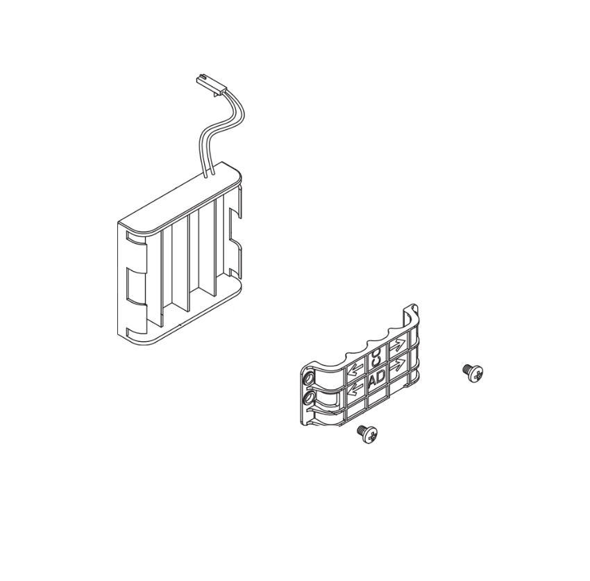
Part number 46929063 is the Schlage OEM 4AA Battery Holder Kit for the AD Series and CO Series electronic lock families. If your Schlage AD-200, AD-250, AD-400, or CO Series lock is showing a low battery warning, the batteries have failed completely, or the battery holder assembly itself has become damaged, this guide gives you everything you need: what the 46929063 kit includes, every compatible lock model, how to read the low battery indicators, the correct replacement process pulled directly from Schlage's official documentation, battery failure modes, maintenance intervals, and where to order the genuine OEM part.

Browse the Schlage 46929063 4AA Battery Holder Kit at SecurityParts.com. Same-day shipping on stocked quantities.


What Is Part Number 46929063

Part number 46929063 is the official Schlage OEM designation for the 4AA Battery Holder Kit used in compatible Schlage AD Series and CO Series electronic locks. It is Item 15 in the official Schlage AD Series Service Manual (document 106502) and is the correct factory-replacement interior battery assembly for these lock families.

This is not a generic or aftermarket component. It is a genuine Schlage part manufactured to the exact tolerances and connector specifications required for the AD and CO Series interior escutcheon. Using a non-OEM battery holder in a Grade 1 commercial electronic lock risks improper fit, unreliable electrical contact with the interior main board, and potential voiding of the lock warranty and UL listing compliance.


What the 46929063 Kit Includes

This kit ships with three components as listed in the official service manual:

  • 4AA Battery Holder with Cable, the main plastic housing that holds four AA batteries and connects to the interior main board via an integrated cable harness with a factory connector
  • 4AA Battery Strap, a securing strap that holds the battery holder firmly in place inside the interior escutcheon during door operation, vibration, and thermal cycling
  • Battery Holder Screws (2), two screws used to mount and secure the strap and holder assembly to the interior escutcheon

Batteries are not included. The 46929063 requires four standard AA alkaline batteries, purchased separately. The official Schlage user guides for the AD-200, AD-250, and AD-400 specify alkaline batteries only. Do not use lithium or rechargeable NiMH batteries, the voltage profiles of these battery types cause irregular low-battery detection readings in the AD and CO Series lock electronics.

For ULC-S319 compliant installations, the official Schlage documentation specifies the following AA alkaline battery models: Duracell PC1500 or MN1500, Energizer E91, EN91, AX91, or XR91, and Rayovac 815 or 815-HE.

Schlage 46929063 4AA Battery Holder Kit OEM replacement for AD Series and CO Series electronic locks at SecurityParts.com

Schlage 46929063 4AA Battery Holder Kit. OEM replacement for Schlage AD and CO Series electronic locks. Includes battery holder with cable, battery strap, and two mounting screws. In stock at SecurityParts.com.


Schlage AD Series and CO Series Compatibility

The 46929063 fits both the 4AA battery configuration of the Schlage AD Series and compatible CO Series electronic locks. Verify your lock's battery configuration before ordering, not all AD and CO Series models use the 4AA layout. Some use an 8AA holder instead.


AD-200 and AD-250 Series Compatibility

This battery holder is used in the interior of the following AD-200 and AD-250 configurations, as confirmed in the Schlage AD Series Service Manual:

  • AD-200/250 cylindrical locks, interior portion of the lock body
  • AD-200/250 mortise locks, interior of the mortise lock assembly
  • AD-200 mortise deadbolt, interior of the mortise deadbolt
  • AD-200/250-993-R, S, M, exit trim configurations using the AD-200/250 interior assembly


AD-400 Series Compatibility

This kit is also used in the following AD-400 networked wireless lock configurations:

  • AD-400 cylindrical locks, interior battery assembly
  • AD-400-MS, mortise lock configuration
  • AD-400-MD, mortise deadbolt configuration
  • AD-400-993-R, S, M, exit trim configurations using the AD-400 interior
  • AD-400-993 Series, 993 series networked variants


CO Series Compatibility

Compatible CO Series electronic locks use the same interior battery assembly platform as the AD Series, and 46929063 is listed in CO Series service documentation. Confirm your specific CO Series model against the official service manual before ordering to verify the 4AA battery configuration applies to your unit.


AD Series Technical Certifications

The Schlage AD Series locks that use this battery holder are certified to ANSI/BHMA A156.25 Grade 1, UL 294, UL 10C, FCC Part 15, ADA, and RoHS. Maintaining OEM battery holder components is part of preserving compliance with these certifications. The maximum current requirement for the AD Series is up to 250 mA, and the interior operating temperature range, where the 46929063 operates, is 32°F to 120°F (0°C to 49°C).


4AA vs 8AA: Confirming the Right Battery Holder for Your Lock

The AD Series and CO Series are available in two battery configurations. The 46929063 covers the 4AA configuration. The Schlage 46929097 is the separate 8AA battery holder kit for models that use eight AA batteries. These two kits are not interchangeable.

To identify which configuration your lock uses, remove the interior assembly and examine the existing battery holder. It will clearly show whether it holds four or eight batteries. You can also identify the configuration from your lock's model number suffix or by referencing the Schlage AD Series Service Manual against your specific function and trim code.

Schlage 46929097 8AA Battery Holder Kit, 8AA alternative to 46929063 for larger battery configurations at SecurityParts.com

Schlage 46929097 8AA Battery Holder Kit, the 8AA alternative for AD and CO Series configurations that use eight batteries. Order 46929097 only if your lock uses eight AA batteries. Both kits stocked at SecurityParts.com.


How to Read the Low Battery Warning on Schlage AD Series Locks

One of the most important gaps in every current page ranking for 46929063 is the complete absence of low battery indicator guidance. The official Schlage AD-200 and AD-400 User Guides document this precisely. Understanding the warning signs allows facilities staff to order the 46929063 and replacement batteries before a complete power failure occurs.


AD-200 and AD-250 Low Battery Indicators

On the Schlage AD-200 and AD-250 offline locks, the low battery condition is indicated as follows, per the official Schlage AD-200 Offline Lock User Guide:

  • Low battery warning (AA batteries): After a credential is presented, the left Schlage button produces 9 red blinks, then the normal access indicator follows
  • Low battery warning (coin cell): After a credential is presented, the right Schlage button produces 9 red blinks
  • Battery failure: No LED or beep response. Valid credentials do not grant access. The mechanical override key must be used to unlock the door until batteries are replaced
  • Beeper behavior: During a low battery condition, the reader beeper is temporarily disabled. It returns to normal function once batteries are replaced
  • Operating window after low battery warning: The lock is intended to operate for approximately 500 credential cycles in low battery condition before complete failure

Important: If your lock shows no LED and no beep, and valid credentials are not granting access, the batteries have likely reached complete failure, not just low battery. Replace the batteries immediately and use the mechanical override key for access in the interim.


AD-400 Networked Lock Low Battery Indicators

On the Schlage AD-400 networked wireless locks, the low battery behavior differs from the offline AD-200/250 series, per the official Schlage AD-400 User Guide:

  • Low battery warning: Approximately one month before the end of battery life, the lock sends a Low Battery Trouble signal to the PIM400 access control panel, which in turn sends a Trouble signal to the access control system, typically generating an alert at the head-end software
  • SUS communication failure in low battery: When a low battery condition is present, the lock may not have sufficient power to communicate with the Setup Utility Software (SUS). If the Schlage button lights solid red for one second when SUS communication is initiated, the battery level is too low to support communication, replace batteries immediately
  • Battery failure: No LED or beep response. Valid credentials do not grant access. Mechanical override key required

Key difference: The AD-400's networked connection means the access control panel receives the battery alert automatically, approximately one month in advance. Facilities managing AD-400 locks through a central access control system should ensure the panel is configured to forward Low Battery Trouble signals to maintenance staff.


Battery Failure Modes: What Happens When the Battery Dies Completely

Both the AD-200/250 and AD-400 series allow the battery failure mode to be configured via the Setup Utility Software (SUS). The official Schlage documentation defines three modes:

  • Fail As-Is (default): The lock remains in its current state, locked or unlocked, until batteries are replaced. This is the factory default for both series
  • Fail Unlocked: The lock unlocks and remains unlocked until batteries are replaced. Use with caution on security-critical openings. Not available when the lock is externally powered
  • Fail Locked: The lock locks and remains locked until batteries are replaced. Not available when the lock is externally powered

Knowing the configured failure mode for each AD or CO Series lock in your facility is essential for emergency planning. If a lock fails in an unexpected state, the first action is to use the mechanical override cylinder, not to assume the lock is defective.

For a broader understanding of how battery-powered electronic locks integrate with access control systems, see the access control and commercial door hardware integration guide.


Schlage 46929063 Battery Replacement: Step-by-Step Process

The following steps reflect the battery replacement procedure documented in the official Schlage AD-200, AD-250, and AD-400 User Guides. Always consult the official documentation for your specific model and configuration before beginning service work.

Tools and Materials Required

  • Four fresh AA alkaline batteries (alkaline only, not lithium, not rechargeable)
  • Phillips head screwdriver
  • Torx T10 driver (required on some AD Series interior trim screws)
  • Clean dry cloth
  • Replacement Schlage 46929063 kit if the holder assembly itself needs replacement


Step 1: Present a Valid Credential First

Before removing the interior assembly, present a valid credential to confirm the lock is in a known operational state. This is particularly important if the batteries are in a low, but not failed, condition, as the lock should still respond. Knowing the current state prevents unexpected lockouts during servicing.


Step 2: Remove the Battery Cover

Remove the battery cover from the interior escutcheon. On most AD Series configurations, the cover is secured by a single screw. Keep the screw and cover together, they are not included in the 46929063 replacement kit. The battery cover is a separate part (Schlage part 4C for the 4AA cover).


Step 3: Remove the Battery Bracket

Remove the battery bracket (strap) by unscrewing the two securing screws. The official Schlage guidance specifies one critical precaution here: do not allow the battery pack to hang from the wires. Support the battery holder as you remove the strap to prevent stress on the cable connector at the interior main board.


Step 4: Disconnect the Cable Connector

With the bracket removed and the holder supported, locate the cable connector running from the battery holder to the interior main board. Press the connector release tab and pull the connector straight out from the board. Always pull on the connector body, not on the cable wires, pulling on the wires can damage the harness and create an intermittent connection that is difficult to diagnose later.


Step 5: Install Fresh Batteries or the Replacement Kit

If you are replacing only the batteries: remove the four AA batteries from the holder, note the polarity markings inside the holder, and install four fresh AA alkaline batteries with the correct orientation. Incorrect orientation is one of the most common causes of failed battery replacement, the lock will not power up if even one battery is reversed.

If you are installing a replacement battery holder kit: transfer four fresh AA alkaline batteries into the new holder using the correct polarity orientation, then proceed with reassembly using the new strap and screws from the kit.


Caution from official Schlage documentation: There is a danger of explosion if the battery is incorrectly replaced. Replace only with the same or equivalent type. Dispose of used batteries according to the manufacturer's instructions.


Step 6: Reconnect and Reinstall

Reconnect the battery cable to the interior main board connector until it clicks into place. Position the battery holder correctly inside the escutcheon, reinstall the battery strap over the holder, and tighten the two screws. Reinstall the battery cover, taking care not to pinch the battery wires between the cover and the escutcheon body when the cover is seated, the official Schlage guidance specifically warns against this, as pinched wires cause intermittent power faults that can be misdiagnosed as battery or main board failures.


Step 7: Test the Lock

Present a valid credential to verify the lock responds correctly. On the AD-200/250, expect a normal LED and audible indicator. On the AD-400, verify the lock communicates with the access control panel and no Low Battery Trouble signal is present. If the lock does not respond after battery replacement, the most common cause is the cable connector not being fully seated, disconnect and reconnect it before concluding the part has failed.

Note from Schlage's official documentation: Replacement of batteries does not affect any programmed data. Credential assignments, access schedules, and lock configuration are stored in non-volatile memory and are not lost during battery replacement.


Battery Maintenance for Schlage AD and CO Series Locks

Use Alkaline Batteries Only

Schlage specifies alkaline AA batteries exclusively for the AD and CO Series. The reason is voltage profile consistency: alkaline batteries maintain a more predictable discharge curve than lithium or NiMH alternatives. Lithium batteries operate at a slightly higher voltage that can skew the lock's battery level readings. Rechargeable NiMH batteries operate at 1.2V instead of the 1.5V of alkaline cells, which causes the lock's electronics to interpret them as partially discharged from the moment they are installed, triggering premature low battery warnings.


Replace All Four Batteries at the Same Time

Replace all four AA batteries in the 46929063 holder simultaneously. Mixing batteries of different ages, even partially used batteries from the same brand, causes uneven drain and shortens the effective service life of the new cells. A mismatched set also produces inconsistent voltage readings that can trigger false low battery conditions.


Establish a Preventive Maintenance Schedule

For high-traffic access control openings, check battery status every six months. For standard commercial openings with moderate credential traffic, annual replacement is a common starting interval. Adjust the schedule based on how frequently low battery warnings appear, repeated early warnings indicate higher-than-expected credential traffic or a temperature-related drain issue.

For facilities running AD-400 networked locks through a central access control panel, use the Low Battery Trouble signal as your scheduling trigger. The signal appears approximately one month before expected battery failure, enough lead time to schedule replacement without emergency urgency. For a complete preventive maintenance framework covering all commercial door hardware, see the commercial door hardware maintenance checklist.


Inspect the Holder Assembly During Every Battery Change

Every time batteries are replaced, briefly inspect the holder assembly for battery contact corrosion, cable connector damage, strap wear, or housing cracks. Catching early deterioration during a planned battery change costs a few minutes. An emergency holder replacement after complete lock failure can take a lock out of service for hours. If any damage is found, order a replacement 4AA Battery Holder Kit from SecurityParts.com for the next scheduled service visit.


Keep Spare Kits On-Site for Large Facilities

Facilities managing ten or more Schlage AD or CO Series locks benefit from keeping one or two spare battery holder kits on hand. When a holder assembly fails unexpectedly, an on-site spare allows same-day restoration without waiting for shipping. This practice is especially important for healthcare facilities, government buildings, and educational institutions where electronic lock downtime on a critical opening is not operationally acceptable.


Other Schlage AD and CO Series Parts at SecurityParts.com

SecurityParts.com stocks a complete range of OEM Schlage AD Series and CO Series service replacement parts. All part pages listed below are confirmed live at SecurityParts.com.

Browse the complete Schlage hardware parts range at the Schlage commercial hardware catalog. For guidance on OEM vs aftermarket parts for commercial electronic locks, see the OEM vs aftermarket commercial door hardware guide. For a broader look at Schlage cylindrical and electronic lock parts, see the cylindrical lock parts guide and the Schlage commercial lock parts guide.

Schlage commercial hardware parts including AD Series and CO Series electronic lock components at SecurityParts.com

Schlage commercial hardware parts at SecurityParts.com, OEM replacement parts for AD Series, CO Series, L-Series, ND Series, and ALX Series electronic and mechanical locks. In stock with same-day shipping.


Why Choose SecurityParts.com for Schlage 46929063

SecurityParts.com has stocked genuine OEM Schlage commercial hardware since 2001. Every part shipped is a factory-genuine replacement.

OEM Only, No Aftermarket Substitutes

Every kit stocked at SecurityParts.com is genuine Schlage OEM. Non-OEM battery holders may not fit precisely within the AD or CO Series interior escutcheon, may use lower-quality battery contacts that cause intermittent power connections, and may not include all three kit components. OEM compliance matters particularly for facilities operating under warranty, UL compliance requirements, or service contracts specifying genuine manufacturer parts.


Same-Day Shipping on Stocked Parts

This part is stocked and available for same-day shipping from US warehouses on stocked quantities. For time-sensitive lock service, same-day dispatch reduces the window a critical opening is without full electronic access control function.


Full AD and CO Series Parts Coverage

SecurityParts.com stocks the complete range of AD Series and CO Series service replacement parts from battery holders through main boards, REX switches, door position switches, tailpiece kits, and interior baseplate assemblies. A single order can cover all parts identified during a scheduled service visit. Browse the complete commercial door hardware parts catalog at SecurityParts.com.

Order the Schlage 46929063 4AA Battery Holder Kit at SecurityParts.com. For specification questions, call 845-935-0301 or visit the contact page.

About the Author

This guide is published by the commercial door hardware team at SecurityParts.com, a supplier of genuine OEM Schlage, Von Duprin, LCN, Falcon, and Detex parts since 2001. The technical information in this guide is drawn directly from the official Schlage AD Series Service Manual (document 106502), the Schlage AD-200 Offline Lock User Guide (document 102107), the Schlage AD-250 Offline Lock User Guide (document 102108), and the Schlage AD-400 and AD-402 Networked Wireless Lock User Guide (document 104387). For 46929063 availability and same-day shipping, call 845-935-0301 or visit SecurityParts.com.


Commercial Door Closer Sizing Guide: LCN Sizes 1-6, Mounting Types, ADA and Backcheck Explained

Door closer size numbers (1 through 6) indicate spring power, not physical dimensions. Higher numbers mean stronger spring tension for heavier or wider doors. The LCN 4040XP ships at size 3 and is field-adjustable from size 1 through 6 using the green dial. For standard interior doors (34 to 36 inches), size 3 is the starting point. For standard exterior entries (36 inch, moderate wind), size 3 to 4. For wide heavy exteriors in high wind (42 to 48 inch), size 5 to 6. Critical sizing rule: parallel arm mounting is approximately 25 percent less mechanically efficient than regular arm. Always specify one size higher for parallel arm on exterior doors. ADA requires no more than 5 pounds of opening force on interior accessible routes: verify with a calibrated gauge after final adjustment. The LCN 4040XP carries a 30-year mechanical warranty and replaces the older 4041 Series using the same mounting hole pattern.

Door closer sizing is the specification decision that generates the most field callbacks on new commercial installations. The two most common outcomes of getting it wrong: a door that does not fully close and latch (under-powered closer for the door or the environment), or a door that is too hard to open for ADA compliance (over-powered closer on an interior accessible route). Neither failure is visible at rough-in. Both show up after occupancy when correcting the problem means ordering new parts and sending a technician back.

Browse LCN door closer parts at SecurityParts.com: LCN 4040XP, 4000 Series, 1000 Series, and Sentronic parts, complete LCN door closer parts catalog, LCN 4040XP parts guide by series, and the complete Allegion hardware and parts catalog.

25% Mechanical efficiency reduction of parallel arm vs regular arm at the same spring size setting
Size 3 LCN 4040XP ships from factory adjusted to size 3; field-adjustable 1-6 without removal or special tools
5 lbs ADA maximum opening force on interior doors on accessible routes; verify with calibrated gauge after setting
30 years LCN 4040XP limited mechanical warranty; longest warranty in the LCN closer lineup


What Door Closer Size Numbers Actually Mean

The number on a door closer does not describe the physical size of the unit. Most Grade 1 commercial door closers from LCN, Norton, Sargent, and similar manufacturers are physically comparable in body length (the LCN 4040XP body is approximately 10 inches long regardless of size setting). The size number describes the spring power: the tension stored in the internal spring mechanism that drives the door closed.

A higher size number produces more closing force throughout the door's closing arc. This greater force is needed on wider doors (more leverage required to overcome the door's weight and inertia at the pivot point) and on exterior doors exposed to wind pressure that resists closing. A size 1 closer on a 48-inch exterior hollow metal door in a wind-exposed location will not reliably close and latch the door. A size 6 closer on a 30-inch interior office door will produce an opening force that fails ADA requirements and creates an accessibility barrier for mobility-impaired users.


The LCN 4040XP Green Dial: Visual Spring Size Adjustment

The LCN 4040XP includes a patented green dial indicator at the end of the closer body that provides a visual reference for the current spring size setting. Unlike older closers where size adjustment required counting turns of an unmarked spring adjustment nut, the 4040XP's dial shows the size number clearly. Adjustment is made with a standard box wrench on the spring adjustment nut; the green dial rotates to show the current size without requiring the closer to be removed or the body to be opened. The closer ships from the factory set to size 3.

 
1Lightest

Very lightweight interior doors, 24 to 30 inches wide. Low-resistance opening required for ADA-sensitive applications with light doors.


2Light

Light interior doors, 30 to 34 inches wide. Interior office doors and light residential-adjacent commercial applications.


3Standard

Standard commercial interior doors, 34 to 36 inches wide. Factory default setting on LCN 4040XP. Most common specification for interior corridor doors.


4Heavy

Standard exterior entry doors, 36 to 42 inches. Interior doors with weatherstripping drag or heavy door construction. Parallel arm on 36-inch exterior.


5Extra Heavy

Wide exterior doors, 42 to 48 inches, or standard exterior in high-wind exposure. Parallel arm on 42-inch exterior. Heavy hollow metal with extensive weatherstripping.


6Maximum

Widest exterior doors, 48 inches or larger. Maximum wind-exposure exterior. Oversized institutional doors. Parallel arm on wide exterior in high wind.


Door Closer Sizing Table: Spring Size by Door Width and Application

ApplicationDoor WidthRegular Arm SizeParallel Arm SizeNotes
Light interior office or storage24 to 30 in1-22-3Low ADA opening force priority
Standard interior corridor30 to 34 in2-33-4Most common interior specification
Standard interior commercial34 to 36 in34LCN 4040XP factory default setting
Exterior entry, low wind exposure36 in3-44-5Weatherstripping adds resistance
Exterior entry, moderate wind36 to 42 in4-55-6Verify ADA compliance on accessible sides
Wide exterior or high wind42 to 48 in5-66Consider heavier-duty LCN 4040XP EDA arm
Fire door, interior corridor34 to 36 in3-44-5Must latch from any open angle; UL 10C required
Fire door, stairwell (wider)36 to 42 in4-55-6Higher spring power for reliable latching
 
 
Why the table is a starting point, not a guarantee: These recommendations assume a standard door with normal hinge friction, no weatherstripping, and no threshold drag. Every additional resistance source (compression weatherstripping, high-pile carpet threshold, stiff threshold seal, heavy door weight above standard) increases the required spring size independent of door width. Always field-test the final installed closer under actual conditions by releasing the door from full open and confirming it closes and positively latches without assistance. If it does not, increase spring size. If the ADA opening force gauge reads over 5 pounds on an accessible interior route, decrease spring size.


The Three LCN 4040XP Mounting Configurations


Regular Arm (Pull Side)

Hinge side mounting; highest efficiency

Closer body mounts on the hinge side (pull side) of the door. The arm extends from the pinion to a shoe on the door frame. This is the highest mechanical efficiency configuration: the arm geometry transmits spring force to the door with the least energy loss throughout the closing arc.

The LCN 4040XP ships tri-packed with hardware for regular arm as the default configuration. Maximum opening with standard template: 120 degrees.

Use when: Pull-side mounting is architecturally acceptable, the door opens away from the approach corridor, and maximum mechanical efficiency is the priority (exterior doors, heavy doors, fire doors).


Parallel Arm (Push Side)

Push side; 25% efficiency reduction vs regular arm

Closer body mounts on the push side of the door. The arm runs parallel to the door face toward the frame. Push-side mounting keeps the closer body away from the corridor approach side, providing better vandalism resistance and a cleaner appearance on the approach side.

This is the dominant specification for school corridors, healthcare corridor doors, and government buildings where vandalism or corridor aesthetics are priorities. The 25 percent efficiency reduction compared to regular arm is the critical specification fact.

Use when: Push-side mounting is required for aesthetics or vandalism resistance. Always specify one size higher than the regular arm table recommendation.


Top Jamb (Push Side)

Frame head mounting; push-side alternative

Closer body mounts on the frame head (top of the door opening). The arm extends from the frame-mounted body down to a shoe on the door face. This is a push-side mounting alternative when parallel arm is not feasible due to door rail height (narrow top rail on aluminum storefront doors), frame conditions, or minimum clearance requirements.

The LCN 4040XP requires a minimum 1-1/4 inch top rail for standard top jamb mounting; 2-1/4 inch with the 4040-18TJ plate; 3 inches with the 4040-18G plate for flush ceiling applications.

Use when: Parallel arm is not feasible and push-side mounting is required.

 
The parallel arm undersizing error that causes most closer field callbacks on new commercial projects: A contractor specifies size 3 LCN 4040XP in parallel arm on a 36-inch exterior door with weatherstripping, following the regular arm sizing table. After installation, the door does not latch reliably against wind pressure. The correct specification is size 4 for this application: one step higher than the regular arm size 3 recommendation, to compensate for the 25 percent parallel arm efficiency reduction. This error is the single most common LCN closer specification mistake and generates more field callbacks than any other closer selection issue. Before finalizing a parallel arm exterior door specification, apply the +1 size rule.


ADA Opening Force Compliance: More Than a Size Table Decision

ADA and ICC A117.1 require no more than 5 pounds of opening force at the door handle or lever on interior doors on accessible routes. The closer size table provides starting recommendations, but the actual opening force the person in the wheelchair encounters depends on multiple factors beyond spring size:


Door weight: A heavy solid core wood door or thick hollow metal door requires more spring power to close (requiring a larger size) but also requires more force to push open. On ADA-accessible interior routes with heavy doors, the conflict between fire door latching requirements and ADA opening force limits can be difficult to resolve with spring size alone.


Hinge friction: Worn hinge bearings or dry hinge pins increase the resistance to door rotation. This friction adds to the effective opening force without changing the spring setting. Worn hinges on an ADA-accessible door should be replaced before attempting to meet the 5-pound limit by reducing spring size.


Weatherstripping drag: Compression weatherstripping creates significant resistance near the closed position. A door that requires 4 pounds to open from 30 degrees may require 7 or 8 pounds to push open from the fully latched position against compressed weatherstripping. Weatherstripping drag is not reflected in the standard size table.


Threshold resistance: High-pile carpet or stiff threshold seals add opening force that varies with wear. A door that passes the 5-pound ADA test when new may fail after carpet compresses and stiffens over time.


The calibrated force gauge verification step that most contractors skip: After setting the spring size and closing speed on an ADA-accessible door, the only reliable way to confirm ADA compliance is to measure actual opening force with a calibrated push-pull gauge at the door handle height (34 to 48 inches from the floor). The gauge must be pushed steadily (not jerked) to measure the sustained opening force, not the initial breakaway force. A door that reads 4.8 pounds in October may read 7 pounds in January if it is an exterior door and the hydraulic fluid thickens. ADA verification should be conducted at the seasonal conditions where force is highest, not just at installation commissioning.


Closer Valve Adjustments: Sweep Speed, Latch Speed, and Backcheck

ValveControlsClockwise (CW)Counterclockwise (CCW)Notes
S (Sweep)Closing speed from full open to approximately 10-15 degrees from closedSlower closing (more resistance)Faster closing (less resistance)Set first; adjust until door moves at controlled sweep speed
L (Latch)Final 10-15 degrees of closing arc into latched positionSlower final actionFaster final closing action (helps latching)Set second; door must latch securely without slamming
BC (Backcheck)Resistance when door is opened rapidly past approximately 70-75 degreesStronger backcheck (more resistance)Lighter backcheckSet last; prevents door from slamming open against stop


Correct Valve Adjustment Sequence

Adjust in order: sweep speed first, then latch speed, then backcheck. Adjusting out of sequence wastes time because each valve affects the next. After each adjustment, cycle the door at least 10 times to allow the hydraulic fluid to redistribute before evaluating the result. Hydraulic fluid takes several cycles to reach a stable distribution state after a valve adjustment.


Backcheck: Why It Is Essential on Exterior Doors

Backcheck is a hydraulic resistance function that cushions the door against rapid opening impacts beyond approximately 70 to 75 degrees. Without backcheck, a strong wind gust or a person pushing the door open quickly will drive it against the door stop, frame, or adjacent wall at full speed, potentially bending the closer arm, stripping the door spindle, or cracking glazing in the door or adjacent sidelight. Backcheck does not prevent the door from opening fully: it decelerates the door before impact. Engage backcheck on every exterior door installation and any interior door where the swing path has limited stopping clearance.


LCN 4040XP Specifications: Complete Reference

LCN 4040XP Series: Confirmed Technical Specifications

Body construction
Cast iron with full complement bearing
Piston diameter
1-1/2 inch (38 mm)
Pinion construction
Double heat-treated steel
Hydraulic fluid
All-weather Liquid X (temperature stable)
Handing
Non-handed (works on left or right swing doors)
Spring size range
Adjustable 1-6 (shipped at size 3)
Interior door maximum
5 feet (60 inches) wide
Exterior door maximum
4 feet (48 inches) wide
ADA capability
Under 5.0 lbs on 36-inch door when adjusted
Grade
ANSI/BHMA A156.4 Grade 1
Fire door listing
UL and cUL listed under UL 10C
Mechanical warranty
30-year limited
Standard mounting
Tri-pack: regular arm, top jamb, parallel arm
Maximum opening
120 degrees with standard template
4041 Series retrofit
Direct drop-in: same mounting hole pattern


LCN 4040SE Sentronic: Electromagnetic Hold-Open for Fire Doors

The LCN 4040SE Sentronic is the version of the 4040 Series that includes an integrated electromagnetic hold-open coil. The hold-open coil receives 120V power from the building wiring and holds the closer arm in the open position, keeping the door open during normal building operations. When the fire alarm panel activates, it interrupts power to the hold-open coil. The closer spring immediately drives the door to the closed and latched position without any human action.

This is the NFPA 80 Section 6.6.1 compliant hold-open specification for fire-labeled door assemblies. Section 6.6.1 requires that any hold-open device on a fire door be capable of releasing automatically upon fire alarm activation. Standard friction hold-open arms on door closers do not meet this requirement because they require someone to manually push the door closed. The Sentronic's automatic release on alarm activation is what makes it compliant.

 
The non-compliant hold-open that most commercial buildings have on fire corridor doors: Many buildings have fire-labeled corridor doors being held open with standard friction hold-open arms, door stops, or wedges. None of these release automatically on fire alarm. None comply with NFPA 80 Section 6.6.1. Inspectors cite these every year in NFPA 80 annual inspections. The correct hardware is the LCN 4040SE Sentronic, which integrates with the building's fire alarm system and releases automatically on alarm. Browse LCN 4040SE Sentronic parts and replacement components at SecurityParts.com.

Sentronic specifications: 120V power to the closer body, 10-year mechanical warranty, 2-year electrical warranty. Available in the same arm configurations as the standard 4040XP.


Fire Door Closer Requirements: UL 10C and Positive Pressure

Every LCN 4040XP Series closer carries UL 10C listing, which is the Positive Pressure Fire Testing standard required by NFPA 80 for all hardware on fire-labeled door assemblies. UL 10C tests hardware under the positive pressure conditions of an actual fire: the outward pressure from fire-driven gases pushing against the door assembly. A closer that is only Grade 1 rated without UL 10C listing cannot be legally installed on a fire-rated door assembly regardless of its mechanical performance.

For fire-rated doors, size the closer to ensure positive latching from any open angle. The NFPA 80 inspection test (release from full open, confirm it closes and latches without assistance) is the compliance test. A fire door closer that passes the ADA 5-pound test but fails to latch consistently from full open under all seasonal conditions does not satisfy NFPA 80 requirements. The fire door latching requirement takes precedence over the ADA opening force preference on fire doors.

Browse LCN door closer parts for fire door applications and complete LCN 4040XP replacement parts catalog at SecurityParts.com. Pre-order closer sizing support at 845-935-0301 or the contact page.


Why Choose SecurityParts.com for LCN Door Closer Parts

Parallel arm 25% efficiency documentation, calibrated ADA gauge verification requirement, Sentronic NFPA 80 compliance detail, 4040XP as 4041 direct retrofit, and same-day OEM shipping.


Parallel Arm Efficiency Rule

We document the 25 percent parallel arm efficiency reduction and the specific requirement to size up one step for parallel arm exterior doors. This is the most common LCN closer specification error and is not documented at the parts ordering level by any competitor.


ADA Gauge Verification

We document that the size table provides starting points and that actual ADA compliance requires a calibrated push-pull gauge verification at door handle height under seasonal worst-case conditions, not just at installation commissioning.


Sentronic NFPA 80 Compliance

We document the NFPA 80 Section 6.6.1 requirement for automatic fire alarm release on fire door hold-open devices and why friction hold-open arms do not comply, making the Sentronic the correct specification.


Same-Day OEM Shipping

LCN 4040XP parts ship same day from US warehouses. The 4040XP is a direct 4041 retrofit. Call 845-935-0301 or the contact page for closer sizing support.


What Makes Security Parts Different for LCN Closer Parts and Specification

  • We document the 25 percent parallel arm mechanical efficiency reduction with the specific sizing rule: add one spring size to every parallel arm exterior door specification. This is the most common LCN closer specification error causing field callbacks and is not documented by any competitor at the parts ordering level.
  • We document why the size table is a starting point and why ADA compliance requires a calibrated gauge measurement after installation, not reliance on the table alone. Additional resistance sources (weatherstripping, heavy door weight, worn hinges, carpet thresholds) affect opening force independently of spring setting.
  • We document the NFPA 80 Section 6.6.1 automatic release requirement for fire door hold-open devices and why friction hold-open arms produce a cited NFPA 80 deficiency at every annual inspection. The LCN 4040SE Sentronic with fire alarm panel integration is the only code-compliant hold-open option.
  • We document the LCN 4040XP as a direct drop-in retrofit for the older LCN 4041 Series using the same mounting hole pattern, making it the automatic first choice for all 4041 replacements in the field without requiring new frame preparation.
  • All LCN parts at SecurityParts.com are OEM from authorized Allegion distribution, covered under LCN's 30-year mechanical warranty for the 4040XP Series. Browse LCN 4040XP parts, complete door closer parts catalog, and all Allegion parts at SecurityParts.com.
  • Free shipping on orders over $450. Same-day shipping from US warehouses on stocked parts. 30-plus years of commercial door hardware experience.


Frequently Asked Questions About Commercial Door Closer Sizing


What do door closer size numbers (1 through 6) actually mean?

Size numbers indicate spring power, not physical dimensions. Most Grade 1 commercial closer bodies are approximately the same length regardless of size number. Size 1 is the lightest spring, suitable for very lightweight interior doors. Size 6 is the strongest, required for wide, heavy exterior doors in high-wind locations. The LCN 4040XP ships at size 3 (the most common interior commercial setting) and is field-adjustable from 1 through 6 using the green dial indicator without removing the closer.


Why does parallel arm mounting require a higher closer size than regular arm?

Parallel arm mounting is approximately 25 percent less mechanically efficient than regular arm mounting. The arm geometry in parallel arm reduces the mechanical advantage at the critical final closing arc, delivering less effective closing force at the same spring size. A parallel arm size 3 delivers approximately the same effective force as a regular arm size 2 on the same door. Always specify one spring size higher for parallel arm applications than the regular arm table recommends, especially on exterior doors exposed to wind pressure.


What is the ADA opening force requirement for commercial door closers?

ADA and ICC A117.1 require no more than 5 pounds of opening force at the door handle on interior doors on accessible routes. The size table provides starting points, but actual opening force depends on door weight, hinge friction, weatherstripping drag, and threshold resistance in addition to spring setting. Always verify ADA compliance with a calibrated push-pull gauge at door handle height (34 to 48 inches) after final adjustment. Seasonal temperature changes affect hydraulic fluid viscosity and can increase opening force in cold weather beyond the summer commissioning reading.


What is the backcheck function on a door closer and when should it be used?

Backcheck creates a cushioned hydraulic resistance when the door is pushed open rapidly past approximately 70 to 75 degrees, decelerating the door before it strikes a wall stop. It prevents door-to-wall impact damage, closer arm bending, and spindle strip. The backcheck valve is separate from the sweep and latch valves. Adjust after sweep and latch speeds are set: turn clockwise for stronger backcheck, counterclockwise for lighter. Use backcheck on all exterior doors and any interior door where the swing path has limited stopping distance.


What is the LCN 4040SE Sentronic and how does it comply with NFPA 80?

The Sentronic is an electromagnetic hold-open closer that holds fire doors open during normal operations and releases automatically on fire alarm activation by current interruption to the hold-open coil. This satisfies NFPA 80 Section 6.6.1, which requires any hold-open device on a fire door to release automatically on fire alarm. Friction hold-open arms require manual release and do not comply. The Sentronic carries a 10-year mechanical warranty and 2-year electrical warranty. It is the only code-compliant hold-open specification for fire-labeled corridor doors.


Is the LCN 4040XP a direct replacement for the older LCN 4041 Series?

Yes. The LCN 4040XP uses the same mounting hole pattern as the LCN 4041 Series. It is a direct drop-in replacement for any existing 4041 installation without new frame preparation or drilling. The 4040XP improves on the 4041 with a cast iron body, double heat-treated pinion, Extra Duty Arm option, all-weather Liquid X fluid, green dial spring size indicator, and a 30-year limited mechanical warranty. When replacing a failed 4041 closer, order the 4040XP for a direct hardware-compatible upgrade.

Schlage L9692EU: Motorized Latch Retraction with Lever Control, Complete Guide

The Schlage L9692EU is a Grade 1 L-Series mortise lock that combines motorized latch retraction with electrified outside lever control. Unlike the L9580, which only retracts the latch on signal, the L9692EU also controls the outside lever electronically, locking or unlocking it based on the access control credential or signal received.

It operates on 24V DC, runs the field-selectable EL (electrically locked, fail safe) or EU (electrically unlocked, fail secure) mode, and is available with RX and LX monitoring options. SecurityParts.com stocks the L9692EU chassis with LX and the L9692EU chassis with RX and LX. Call 845-935-0301 for configuration support before ordering.

Most access control integrators know the Schlage L9692EU by its model number before they know what it actually does. That is a reasonable starting point, model number lookups are how this hardware gets specified in the field, but the model number alone does not tell you whether it is the right function for the opening, how to wire it correctly, or what happens to the lever when the power goes down.

This guide covers all of it: what the L9692EU does and how it differs from latch-only mortise locks, the EL vs EU mode decision, wiring specifications, how the L9692EU compares to the L9695EU and L9696EU functions, RX and LX selection, common install errors, and where to source the replacement chassis. Browse the full Schlage L-Series mortise lock parts catalog at SecurityParts.com.


What the Schlage L9692EU Actually Does

The Schlage L9692EU runs one function that separates it from every other L-Series function: it controls the outside lever electronically while simultaneously providing motorized latch retraction. Those are two distinct electrified operations working in the same chassis.

On a mechanical storeroom lock like the L9080, the outside lever is permanently fixed. The door only opens from outside with a key. On the L9580, motorized latch retraction lets the door release on signal, but the outside lever remains mechanically fixed. The L9692EU adds a third layer: the outside lever itself can be electrically locked or unlocked in addition to latch retraction. When the lever is electrically unlocked, someone can push the lever down and enter without a key. When it is electrically locked, the lever does not move unless a key is used or power state changes.

The inside lever on the L9692EU is always free for egress. This is a life-safety requirement, not an option. Regardless of the power state or mode selected, the inside lever always retracts the latch and allows exit.

For guidance on how this fits into a broader electrified door hardware system, see the access control and commercial door hardware integration guide.

Schlage L9692EU motorized latch retraction chassis with lever control and LX at SecurityParts.com

Schlage L9692EU motorized latch retraction chassis with lever control and LX monitor. OEM replacement chassis stocked at SecurityParts.com.


EL Mode vs EU Mode: Which One Does Your Opening Need

The EL and EU designations in the model name refer to the operating mode of the electrified lever, not the latch retraction. Latch retraction behavior is the same in both modes: powered means latch retracted, unpowered means latch extended. The mode only affects what the lever does.


EU Mode, Electrically Unlocked (Fail Secure)

  • Power applied: Outside lever unlocks, door can be opened by lever without a key
  • Power removed: Outside lever locks, key required for entry
  • Power failure: Door locks, access denied until power is restored or a key is used
  • Use when: The normal state should be locked; a valid credential unlocks the lever for entry
  • Common applications: Office suites, storerooms, server rooms, access-controlled corridors


EL Mode, Electrically Locked (Fail Safe)

  • Power applied: Outside lever locks, key required for entry
  • Power removed: Outside lever unlocks, lever operates freely
  • Power failure: Door unlocks, anyone can enter from outside
  • Use when: The normal state should be unlocked; a lockdown signal secures the door
  • Common applications: Emergency lockdown scenarios, certain ADA-accessible routes

The mode is field-selectable using the mode select switch located on the chassis. Both modes ship in the same physical chassis, the switch sets the behavior.

One critical installation detail: when switching from EU to EL or EL to EU, the lock requires a complete power cycle to synchronize to the new mode. Flip the switch without cycling power and the lock will behave inconsistently until the cycle is completed.

Important, do not share a circuit with solenoid-based devices without transient voltage suppression: Solenoids generate voltage spikes when they de-energize. Those spikes damage the L9692EU motor. Schlage's installation documentation specifies a varistor rated at 35V peak recurrent installed at the solenoid equipment. Omitting this is the leading cause of premature L9692EU motor failure in the first year of service.


Schlage L9692EU vs L9580: Which Function Is Right

The L9580 and L9692EU are the two most commonly specified Schlage motorized latch retraction functions. They are frequently confused during specification because both involve motorized latch retraction and both operate on 24V DC. They do different things.


What the L9580 Does

  • Retracts the latch on signal
  • Outside lever remains mechanically fixed at all times
  • Someone still uses the lever to open the door after the latch retracts
  • Operating mode is not field-selectable, functionally similar to fail secure
  • Peak current: 1.4A (latch retraction only)
  • Best for: signal-release doors, auto operators, infection-control corridors, hands-free entries


What the L9692EU Does

  • Retracts the latch on signal AND controls the outside lever electronically
  • Outside lever locks or unlocks based on the EL or EU mode and the access control signal
  • Someone can push the lever freely when it is electronically unlocked, no key required
  • Operating mode is field-selectable (EL or EU) using the chassis switch
  • Peak current: 1.4A (latch) plus 0.4A (lever control)
  • Best for: access control openings where the lever itself must lock or unlock on credential


The Practical Decision

If the opening needs the door to release on signal and someone still pushes the lever to enter, use the L9580. If the opening needs someone to push the lever down freely on a valid credential, without using a key, use the L9692EU.

Both functions share the same chassis footprint as the mechanical L9000 series, retrofit existing L9000 mortise pockets without frame modification, and are UL listed for 3-hour fire door assemblies.

For a deeper look at the L9580 function, wiring, and applications, see the Schlage L9580 motorized latch retraction guide. For a direct specification comparison between the L9580 and electric strike, see the L9580 vs electric strike guide.


L9692EU vs L9695EU vs L9696EU: Choosing the Right Lever Control Function

The L9692EU is one of three lever-control functions in the Schlage motorized latch retraction family. All three combine motorized latch retraction with electrified lever control, but they differ in which lever or levers are controlled and how the cylinder is configured.

Schlage L-Series mortise lock family including L9692EU electrified functions at SecurityParts.com

Schlage L-Series mortise locks: the Grade 1 commercial standard covering mechanical and electrified functions including L9692EU. Browse L-Series parts at SecurityParts.com.


L9692EU, Outside Lever Control, Outside Cylinder

The L9692EU controls only the outside lever. The inside lever is always free. Outside access requires a key in the outside cylinder, or the access control system unlocking the lever electronically. This is the standard specification for most commercial access-controlled openings: an employee presents a credential, the lever unlocks, they push the lever and enter.

This function is appropriate for single-point entry control where the goal is to grant or deny outside access while preserving free egress from inside at all times.


L9695EU, Both Levers Controlled, Double Cylinder

The L9695EU controls both the outside and inside levers. It has cylinders on both sides. Both levers lock or unlock simultaneously based on the power state. This function is used in high-security applications where inside access must also be controlled, for example, a secure storage room where both entry and exit require an authorized credential.

Important: Any function that can lock the inside lever must be carefully evaluated for compliance with local egress codes and NFPA 80 requirements. On fire-rated doors and doors in egress paths, locking the inside lever may be prohibited or may require additional life-safety measures. Confirm with the authority having jurisdiction before specifying L9695EU on any fire-rated or egress door.


L9696EU, Inside Lever Control, Double Cylinder

The L9696EU controls only the inside lever. The outside lever is fixed, it does not move. Both sides have cylinders. This function is used in applications where the goal is to lock out authorized inside users without affecting outside key access, certain pharmacy windows, controlled dispensing areas, and similar scenarios where outside staff always have key access but inside personnel should only exit on authorization.

For the correct function in the vast majority of commercial access control applications, the L9692EU is the right specification. For full L-Series parts and function diagrams, see the Schlage L-Series parts diagrams guide.


Wiring the Schlage L9692EU: Specifications and Connection

Electrical Specifications

  • Input voltage: 24V DC only (21.6V to 28V DC operating range)
  • Peak current, latch retraction: 1.4 amps
  • Peak current, lever control: 0.4 amps
  • Holding current: 0.1 amps (both functions combined)
  • Operating temperature: 32°F to 120°F (0°C to 49°C)
  • Maximum relative humidity: 85%
  • Connector type: Allegion Connect factory-installed Molex connector with quick-connect harnesses


Power Supply Sizing

Size the power supply for simultaneous peak draw across all connected locks. Two L9692EU locks firing simultaneously can draw close to 3.6 amps for latch retraction plus 0.8 amps for lever control at the moment of actuation. A UL 294 certified access control power supply handles this correctly if specified for the full load.

Always account for peak draw, not holding current, when sizing the supply. Undersized power supplies cause intermittent actuation failures that are frequently misdiagnosed as lock defects.


Allegion Connect Wiring

The L9692EU ships with the Allegion Connect factory-installed Molex connector system. This connector provides quick-connect harnesses that pass through electrified hinges or electrical power transfers (EPT) in the door.

As an alternative, the Molex connector can be removed and the lock wired using traditional wire splicing or the included 6-inch wiring harness if additional wire length is needed. Neither method affects lock performance, the connector is a convenience for installation, not a functional component.

Transient voltage suppression is required when sharing a circuit with solenoid devices: If the L9692EU circuit also powers solenoid-based hardware such as electric strikes or electromagnetic locks, install a varistor rated at 35V peak recurrent at every solenoid device on that circuit. The varistor must be installed at the solenoid, not at the lock. This requirement applies to all variants including L9692EU, L9695EU, and L9696EU. Failure to suppress transient voltage from solenoid de-energization is the most common cause of motor failure in the L9692EU within the first year of service.


RX and LX Options on the Schlage L9692EU

RX: Request to Exit

RX is a switch that closes when the inside lever rotates. It signals the access control panel that a valid exit is occurring from inside the secured area. This serves two purposes: it suppresses the forced-entry alarm that would otherwise trigger when the door opens without a credential, and it logs the exit event in the access control system.

RX is the standard monitoring option for L9692EU installations and is appropriate for the vast majority of commercial access control integrations. If the access control panel needs to distinguish between a door opening from inside and a forced-entry event, RX is required.


LX: Latchbolt Monitor

LX signals whether the latchbolt is extended or retracted at any moment. It tells the access control panel whether the door is actually latched, independent of whether the door is closed. This is a higher level of monitoring than a standard door position switch (DPS), which only signals whether the door is open or closed, not whether it is latched.

LX is specified for high-security openings where confirming the door is truly latched, not just physically closed, is a monitoring requirement. Examples include pharmacy dispensing areas, secured IT rooms, and certain government or institutional applications where partial-latch states must be detected and alarmed.

RX and LX can be ordered together on the same chassis. SecurityParts.com stocks both configurations:

Schlage L9692EU motorized latch retraction chassis with RX and LX monitoring at SecurityParts.com

Schlage L9692EU motorized latch retraction chassis with RX request-to-exit and LX latchbolt monitor. Stocked at SecurityParts.com with same-day shipping on stocked components.


Common Installation Errors on the Schlage L9692EU

The L9692EU is a precision electromechanical assembly. Most field failures trace back to one of four installation errors rather than a defective unit.


1. Sharing a Circuit with Solenoid Hardware Without Transient Suppression

Solenoid de-energization spikes damage the L9692EU motor. Install a 35V peak-recurrent varistor at every solenoid device on the circuit. This is the single largest cause of premature motor failure in the field and the first thing to check when an L9692EU fails inside the first year of service.


2. Wrong Voltage at the Lock Terminals

The L9692EU requires 24V DC within the 21.6V to 28V DC operating range. A 12V panel will not actuate the lock reliably. AC power damages the motor. Confirm voltage with a multimeter at the lock terminals before declaring the unit defective on a new installation.


3. Switching EL to EU Without a Power Cycle

The mode select switch on the chassis sets EL or EU behavior, but the change does not take effect until the lock completes a full power cycle. Switch the mode, then remove and restore power. A lock that behaves inconsistently after a mode change has almost always not been power-cycled after the switch was moved.


4. Improper Coordination with Exit Devices on the Same Opening

On openings where an L9692EU is installed alongside an exit device, the two must be specified and installed so they operate independently. The exit device must always allow egress regardless of the L9692EU power state. Confirm that the exit device specification and installation do not create a dependency on the L9692EU power state for egress operation.

Call 845-935-0301 before ordering a replacement chassis: If an L9692EU has failed in service, confirm the failure mode before ordering a replacement. A lock that does not actuate on signal is most commonly a power supply, wiring, or solenoid-circuit issue, not a failed chassis. SecurityParts.com provides pre-order technical support to confirm the correct part and configuration before the order ships.


How the L9692EU Fits into the L-Series Electrified Family

Allegion's Schlage L-Series motorized latch retraction line covers six functions across two groups. Understanding where the L9692EU sits in this family helps with specification and sourcing when a project requires multiple electrified functions across different openings.


Latch Retraction Only (No Lever Control)

This group includes the L9510 (passage), L9580 (storeroom), and L9582 (institution). These functions retract the latch on signal but do not electrify the lever. The L9580 is the most commonly specified of the three. For L9580 guidance, see the Schlage L9580 guide.


Latch Retraction with Lever Control (L9692 Family)

This group includes the L9692EL/EU (outside lever only), L9695EL/EU (both levers, double cylinder), and L9696EL/EU (inside lever only, double cylinder). The L9692EU is the standard specification in this group for single-point outside access control.

All six functions share the same chassis dimensions as the mechanical L9000 series, retrofit the existing L9000 mortise pocket without frame modification, and are UL listed for 3-hour fire door assemblies.

For OEM vs aftermarket guidance on electrified mortise lock components, see the OEM vs aftermarket commercial door hardware parts guide. For fire-rated door compliance context, see the commercial door fire rating guide.


Sourcing the L9692EU Replacement Chassis

When sourcing a replacement L9692EU chassis, four specifications must be confirmed before the order ships:

  • Monitor configuration (LX only, or RX plus LX)
  • Cylinder format (conventional, FSIC, SFIC, or less cylinder)
  • Finish
  • Door thickness (if anything other than the standard 1-3/4 inch)

Handing is field-reversible on the L9692EU chassis and does not need to be specified at order. The mode (EL or EU) is also field-selectable on the chassis switch, specify the function (L9692) and the mode will be set during installation.

For the trim components that mount on the L9692EU chassis, levers, escutcheons, cylinders, see the Schlage L-Series mortise lock parts guide and the Schlage L-Series parts diagrams. For the broader Schlage hardware catalog including L-Series components, see the Schlage commercial hardware parts page.

Browse all Schlage mortise lock parts at the mortise lock parts catalog. For questions on configuration, availability, or specification verification, call 845-935-0301 or visit the SecurityParts.com contact page.


Why Choose SecurityParts.com for Schlage L9692EU Parts

SecurityParts.com has stocked Schlage commercial hardware since 2001. The L9692EU chassis is stocked in both LX and RX plus LX configurations with same-day shipping from US warehouses on stocked components.

Pre-Order Specification Support

Call 845-935-0301 to confirm the correct chassis configuration, monitor option, cylinder format, and finish, before the order ships. This prevents the wrong-configuration return on a project that cannot wait.


OEM Parts Only

Every L9692EU chassis stocked at SecurityParts.com is genuine Schlage OEM. Non-OEM electrified mortise chassis components void the UL listing on fire-rated assemblies and are not appropriate for Grade 1 access control installations.


Complete L-Series Coverage

SecurityParts.com stocks L9692EU chassis components alongside the full range of L-Series trim, cylinders, escutcheons, and mechanical parts for complete single-order sourcing across a facility. Same-day shipping on stocked components from US warehouses.

Browse the L9692EU chassis with LX, the L9692EU chassis with RX and LX, and the complete commercial door hardware parts catalog at SecurityParts.com.


About the Author

This guide is published by the commercial door hardware team at SecurityParts.com, a supplier of OEM Schlage, Von Duprin, LCN, Falcon, and Detex parts since 2001. The team provides specification and pre-order configuration support for electrified mortise locks, motorized latch retraction functions, and access control hardware integration across commercial, institutional, healthcare, and government facilities. For L9692EU configuration support and same-day shipping availability, call 845-935-0301.

Commercial Door Hardware Maintenance Schedule and NFPA 80 Annual Inspection Guide

NFPA 80 requires annual inspection of all fire door assemblies by a qualified person. The 2022 edition (most widely adopted in current AHJ enforcement) uses a 13-point checklist. Healthcare facilities under CMS jurisdiction enforce the 2010 edition via the 2012 NFPA 101 reference, and fire door deficiencies are cited under K-tag K0223. Industry data shows approximately 76 percent of fire doors fail at least one inspection point. The most common deficiencies: improper door closer adjustment (45 percent of failures), excessive door-to-frame clearances, mechanical dogging of fire exit hardware, and non-listed replacement hardware. Door closer hydraulic fluid thickens in cold temperatures, increasing opening force and creating winter ADA compliance violations on exterior accessible routes that do not exist during warmer months. OEM replacement parts from SecurityParts.com correct the most common deficiency categories before they become inspection citations.

NFPA 80 annual fire door inspection is not a box-checking exercise. It is a documented test of whether each fire door assembly will perform its life safety function in an actual fire event. The 76 percent failure rate from industry inspections means that in a building with 100 fire doors, 76 of them have at least one documented deficiency. Most of those deficiencies are correctable with proper maintenance and OEM parts. This guide covers the complete preventive maintenance schedule for commercial door hardware, the NFPA 80 2022 edition 13-point annual inspection checklist, the most-cited deficiency categories, and the specific parts that address each.

Browse replacement parts for inspection deficiencies at SecurityParts.com: LCN door closer parts for closer adjustment failures, Von Duprin exit device parts for latch and spring deficiencies, Schlage ND Series cylindrical lock parts, Schlage L Series mortise lock parts, and the complete Allegion parts catalog for all inspection-driven replacements.

76% Percentage of fire doors that fail at least one NFPA 80 annual inspection checklist point
13 points NFPA 80 2022 edition inspection checklist items (expanded from 11 in earlier editions)
K0223 CMS K-tag for fire door deficiencies: consistently one of the most-cited Life Safety Code survey findings
45% Estimated proportion of fire door failures caused by improper door closer adjustment alone


Which Edition of NFPA 80 Applies to Your Building

NFPA 80 is updated on a roughly 3-year cycle. Different editions are in force in different jurisdictions, and knowing which edition your AHJ enforces matters because the inspection checklist changed between editions. The 2022 edition expanded the 11-point checklist to 13 points. The current published edition is the 2025 edition.

The 2022 edition is the most widely adopted in current AHJ enforcement for commercial and institutional buildings. Some state and local fire codes still reference the 2019 or 2016 editions. Healthcare facilities under CMS (Centers for Medicare and Medicaid Services) jurisdiction are surveyed under the CMS-mandated 2012 edition of NFPA 101, which references the 2010 edition of NFPA 80. This means a CMS-surveyed hospital must comply with the 2010 NFPA 80 checklist, not the 2022 or 2025 editions. Always confirm the specific edition your AHJ enforces before conducting or commissioning the annual inspection.


The CMS edition discrepancy that generates the most healthcare facility confusion: Healthcare facility managers who research current NFPA 80 requirements and apply the 2022 or 2025 edition requirements during internal audits may prepare documentation that CMS surveyors do not recognize, because CMS surveys under the 2010 edition. Conversely, preparing only for the 2010 edition while the local AHJ has adopted the 2022 edition means the facility does not meet current local fire code requirements. Healthcare facilities are subject to both CMS survey requirements and local AHJ fire code enforcement, and these can require compliance with different NFPA 80 editions simultaneously. Coordinate with your fire door inspection professional to document compliance with both editions.


Preventive Maintenance Schedule: Monthly, Quarterly, and Seasonal Tasks


Monthly Quick Visual Check: All Fire Doors and High-Traffic Hardware

Door closer operation (all fire doors)

Open each fire door fully and release it. The door must return to the fully closed and positively latched position without any manual assistance. A door that stops short of closing, fails to latch, or requires a push to complete the last 6 inches of travel has a closer deficiency under NFPA 80 checklist item 6. Document any door that fails this test and schedule corrective action before the annual inspection.

  • Release door from full open: confirm it closes and latches without assistance
  • Check for slamming: a door that slams has an incorrect latch speed valve setting
  • Observe closing speed: dramatically slower than normal indicates hydraulic fluid thickening or seal failure


Positive latch verification (all fire doors)

After the door closes under closer force, attempt to push it open without operating the lever or pressing the push bar. A fire door that can be pushed open without lever operation after closing under closer force is not positively latched. This is an immediate NFPA 80 deficiency requiring corrective action before the next inspection.


Propped door check

Verify no fire doors are propped or wedged open with non-listed devices: kick-down stops, chair legs, door wedges, or stacked materials. This is the simplest and most prevalent NFPA 80 violation, requires no tools to correct, and is documented on virtually every multi-building inspection as a recurring finding.


Quarterly Hardware Inspection and Adjustment: All Commercial Doors

Door closer inspection and adjustment

Inspect the closer body and arm for hydraulic oil leakage. Any visible oil on the closer body surface, the closer arm, or the door surface below the closer indicates seal failure. A leaking closer cannot maintain consistent speed and force settings: replace it before oil loss produces a closing speed or force deficiency. Adjust sweep speed (S valve) and latch speed (L valve) if the door is closing too fast or too slowly. On LCN 4040XP closers, both valves are located on the end of the closer body and can be adjusted with a small flat-blade screwdriver: turn clockwise to increase speed resistance (slower closing), counterclockwise to decrease resistance (faster closing). Browse LCN 4040XP closer adjustment parts and replacement components.


Exit device inspection

Operate the push bar on every exit device door. The push bar must move smoothly, the latch must retract fully on bar depression, and the latch must return fully to the extended position when the bar is released. A push bar that sticks, a latch that does not fully retract, or a latch that does not return fully on release indicates spring wear or mechanism wear requiring parts replacement. Browse Von Duprin exit device latch return springs and mechanism parts.


Cylindrical and mortise lock inspection

Operate each lever through its full range of motion. A lever that droops (sags below horizontal at rest), does not return to horizontal after release, or is loose on the spindle needs attention. Droop indicates worn spindle or lever return spring. Loose lever indicates worn spindle connection. Browse Schlage ND Series lever return spring and spindle parts.


Hinge check

Open each door and lift gently on the free corner. Movement of more than 1/16 inch at the free corner indicates hinge bearing wear that allows the door to sag, which will eventually produce excessive door-to-frame clearances at the top latch side (the NFPA 80 1/8-inch maximum is easy to exceed on a sagging door). Squeaking hinges indicate dry bearing surfaces: apply light machine oil to the pin.


Seasonal (Fall and Spring) Closer Calibration and Environmental Checks

Fall: exterior closer calibration for winter

Door closer hydraulic fluid thickens in cold temperatures, increasing resistance in both the closing direction and the opening direction. The closing speed may slow to the point where the door does not positively latch on cold mornings. The opening force may increase beyond the ADA 5-pound maximum. Before winter, adjust exterior door closers' sweep speed valves to slightly faster settings that will produce correct latching speeds when the fluid thickens. Check that the adjusted closing force still latches the door positively at the anticipated cold temperature.


The cold-weather ADA compliance violation that only appears in winter and is missed by spring inspections: An exterior closer on an accessible entry that meets ADA opening force limits at the time of the annual inspection in summer may generate significantly more than 5 pounds of opening force in January when the hydraulic fluid is cold and thick. This is a recurring ADA compliance violation in cold climates that is systematically missed by annual inspections conducted in warm weather. The correct practice is to test ADA opening force on exterior accessible entries during winter conditions, not only during the annual inspection. If the closer cannot achieve ADA compliance with cold fluid by valve adjustment alone, the closer cylinder may need replacement with an LCN model rated for low-temperature operation. Browse LCN low-temperature closer components.
 

Spring: check for oil seepage after winter

Temperature cycling through winter stresses hydraulic seals in door closers. As temperatures warm in spring, oil that migrated past a compromised seal during winter may become visible. Inspect all exterior closer bodies for oil film on the housing, arm, or door surface beneath the closer. Spring is the highest-rate season for discovering closer seal failures that developed during winter temperature cycling.


The NFPA 80 2022 Edition 13-Point Annual Inspection Checklist


1

Labels visible and legible

The fire rating label on the door leaf (typically riveted to the hinge edge), frame, glazing, and hardware must be present, visible, and legible. Labels painted over during building repainting are a commonly cited deficiency. Labels are required to remain permanently affixed and legible for the life of the assembly.


2

No open holes or breaks in door or frame surfaces

Any holes, cracks, breaks, or penetrations in the door leaf or frame that were not part of the original listed assembly constitute a deficiency. This includes unauthorized hardware holes, broken glazing retainer areas, or damaged door face material. Minor dents that do not penetrate the door face are not typically cited.


3

Glazing listed and intact

Any glazing in the fire door assembly must be fire-rated, labeled, and free of cracks, chips, or damage. Non-fire-rated glazing (such as standard tempered glass) substituted for fire-rated glazing is a deficiency regardless of appearance. The glazing label must be visible and legible.


4

Door clearances within listed tolerances

Measure door-to-frame clearances at the head (top), both jambs (sides), and the bottom. NFPA 80 specifies maximum clearances: typically 1/8 inch at the head and jambs, 3/4 inch at the bottom (sill clearance). Excessive clearances allow smoke passage and compromise the fire separation. Clearances can increase over time from door warpage, hinge wear, or frame movement.


5

Door operates freely without manual assistance

The door must open and close smoothly without binding, sticking, or requiring extraordinary force. Binding indicates hinge misalignment, frame movement, or door warpage. A door that cannot be opened or closed smoothly by a person of normal strength under normal conditions may fail ADA requirements as well as this inspection point.


6

Self-closing device closes door from any open angle

The door closer (or spring hinge at 20-minute rating) must return the door to the fully closed position from any angle of opening, including full open (90 degrees or more). A door that closes from 30 degrees but stalls at 60 degrees fails this test. Conduct the release test at multiple open angles to confirm consistent closer performance.


7

Positive latching: latch bolt engages strike when door closes

After the closer returns the door to the closed position, the latch bolt must engage the strike plate without manual operation of the lever or any other hardware. This is the most consequential test in the inspection: a door that closes but does not latch provides no fire separation. Verify latch engagement by attempting to push the door open from the closed position without operating the lever.


8

Hardware is listed for the fire door assembly

Every component installed on the fire door assembly must carry a fire listing appropriate to the door's rating and must be compatible with the assembly as specified in the Builders Hardware Template (BHT) for the specific door model. Non-listed replacement hardware (including hardware that appears identical to the listed original) is a deficiency. Verify that every hinge, lock, closer, and exit device carries visible fire rating labels.


9

No field modifications affecting the fire rating

Unauthorized holes, cut-outs, added hardware, or other field modifications that were not part of the original tested assembly void the fire rating and are a cited deficiency. Added hardware includes non-listed kickplates (some kickplates affect door clearances), non-listed viewers, and any surface-mounted device not specified in the door's BHT. Mechanical dogging of fire exit hardware is also cited here as it prevents positive latching.


10

Meeting edge protection for pairs (astragal or edge seal)

Double-door fire assemblies require meeting edge protection: an astragal or meeting edge seal that closes the gap between the two door leaves when both are in the closed position. This seal prevents smoke passage through the center gap before the fire-rated door material reaches its rated performance temperature. Missing, damaged, or improperly positioned meeting edge protection is a deficiency on pair openings.


11

Perimeter seals and gasketing present and intact

Fire door assemblies that require smoke control (S designation) must have perimeter seals or gasketing present and in good condition. Seals that are missing, damaged, compressed flat, or separated from the door or frame edge are a deficiency. Even on non-S-labeled assemblies, any required gasketing specified in the BHT must be present and intact.


12

Required signage present and compliant

NFPA 80 requires certain fire doors to have signage indicating "Fire Door Keep Closed" or similar language specified in the standard. Signage requirements vary by occupancy and door location. Inspect that required signage is present, legible, and correctly positioned. Missing or illegible signage is a deficiency. Decorations affixed to fire doors that cover the required signage or the fire rating label are also cited.


13

Auxiliary hardware does not prevent closing or latching

Any hardware installed on the door or frame that prevents or impedes the door from closing and latching is a deficiency. Common culprits: kick-down door stops (directly prohibited), furniture pushed against the door swing path, non-listed electromagnetic hold-opens not connected to the fire alarm system, and non-listed security bars or barricade devices.


Most Common NFPA 80 Deficiency Categories and the Parts That Fix Them


~45% of failures

Improper Door Closer Adjustment: Door Does Not Close or Latch Fully

The single most common inspection deficiency. Root cause is most often incorrect latch speed valve (L valve) setting that allows the door to slow before the latch engages the strike. Also caused by worn closer springs that no longer produce sufficient force for full closure, or by hydraulic seal failure that allows fluid loss over time.


Adjust before replacing: On LCN 4040XP Series, turn the L (latch) speed valve counterclockwise slightly to increase latch closing speed. If valve adjustment reaches its limit without achieving full latch, or if oil is visible on the closer body, closer spring or cylinder replacement is needed.

LCN door closer parts: springs, cylinders, and adjustment components LCN 4040XP Series complete parts catalog
Common


Excessive Door-to-Frame Clearances: Gaps Exceed 1/8 Inch

Excessive head and jamb clearances allow smoke passage and indicate door warpage, hinge wear, or frame movement. Identify the cause before specifying the fix. Hinge-side gap that is larger at the top than the bottom indicates hinge sagging from worn bearings or loose mounting screws. Tighten hinge screws first. If screws are stripped, use longer screws with Heli-coil inserts to restore thread engagement. If bearing wear is the cause, replace hinges.

Latch-side gap that is excessive indicates strike misalignment or door warpage. Strike adjustment addresses misalignment. Door warpage requires door replacement.

Von Duprin strike plate parts for strike adjustment
Common


Non-Listed Hardware Installed on Fire-Rated Assemblies

Repair personnel install standard commercial hardware in place of fire-listed hardware that appears physically identical. The fire rating label on the device is the only field-visible indicator of fire-listed status. A Schlage ND Series cylindrical lock in the non-fire-rated version is visually identical to the fire-rated version: only the lock case label distinguishes them. Inspect every hardware component label after any repair or replacement on a fire-rated opening. Replace non-listed hardware with OEM fire-listed parts from authorized suppliers.

Schlage ND Series fire-listed cylindrical lock parts (OEM only) Schlage L Series fire-listed mortise lock parts (OEM only)
Common


Mechanical Dogging of Fire Exit Hardware

Facilities staff use hex keys on fire exit devices during business hours to hold the latch retracted, preventing positive latching. This is explicitly prohibited by NFPA 80 and is cited in virtually every multi-building inspection. The corrective action is to remove the dogging key, educate staff, and consider replacing the device with an LD (Less Dogging) version that physically cannot be mechanically dogged, or installing electric dogging connected to the fire alarm panel for the push-pull function without the compliance risk.

Von Duprin exit device LD (Less Dogging) versions and parts


Lubrication Guide: Right Product for Each Hardware Type

Hardware ComponentCorrect LubricantIncorrect (Avoid)Frequency
Cylinder plug (keyway interior)Graphite powder or dry PTFE (Teflon) sprayWD-40, oil, grease (attracts dust, creates gummy residue)Annually or when stiff
Hinge pin and knuckle bearingsLight machine oil (3-in-1 type) or silicone lubricant, applied sparingly to pinExcess grease (collects debris and accelerates bearing wear)Semi-annually or when squeaking
Exit device push bar pivots and latchDry PTFE or light oil applied with cloth to pivot pointsSpray lubricant directly into assembled device (overspray coats springs)Quarterly for high-cycle doors
Closer arm spindle connectionSmall amount of grease at spindle connection point; wipe cleanLubricant inside closer body: sealed hydraulic unit, contamination voids warrantySemi-annually
Mortise lock latch boltLight machine oil on latch bolt face and tailpieceGrease (attracts debris and can harden in cold temperatures)Annually or when sluggish
Strike plate interiorLight oil or dry PTFE on strike keeper interiorNothing inside electric strike keeper (lubricant degrades solenoid components)Annually

For OEM replacement parts when lubrication and adjustment no longer restore correct function, browse LCN door closer parts, Von Duprin exit device parts, Schlage cylindrical lock parts, and Von Duprin complete parts catalog at SecurityParts.com. Parts support at 845-935-0301 or the SecurityParts.com contact page.


Why Choose Security Parts for Inspection-Driven Hardware Parts

CMS K0223 edition discrepancy documented, cold-weather ADA compliance failure mechanism, non-listed hardware identification guidance, LD specification for dogging prevention, and same-day OEM shipping.


CMS Edition Discrepancy

We document that healthcare facilities under CMS jurisdiction must comply with the 2010 NFPA 80 edition (via the 2012 NFPA 101 reference), not the current 2022 or 2025 editions. This edition discrepancy affects which inspection checklist applies for K0223 survey compliance and is not documented by any competitor.


Cold-Weather ADA Closer Failure

We document the hydraulic fluid viscosity increase that causes exterior door closers to exceed ADA opening force limits in winter even though they passed the same test during summer. This seasonal ADA violation is systematically missed by annual inspections conducted in warm weather.


Fire-Listed Hardware Identification

We document that fire-rated and non-fire-rated versions of Schlage ND and L Series locks appear physically identical: the lock case label is the only field-visible indicator. Ordering OEM fire-listed parts from SecurityParts.com prevents non-listed hardware deficiencies.


Same-Day OEM Shipping

OEM parts for inspection deficiency correction ship same day from US warehouses. Call 845-935-0301 or the contact page for inspection-driven part number identification support.


What Makes Security Parts Different for Maintenance and Inspection Parts

  • We document the CMS K0223 tag and the edition discrepancy between what healthcare facilities read in current NFPA 80 publications and what CMS actually surveys against (the 2010 edition via the 2012 NFPA 101 reference). No competitor documents this at the parts ordering level, and it creates false compliance confidence in healthcare facility maintenance programs.
  • We document the cold-weather ADA opening force violation on exterior door closers as a seasonal phenomenon caused by hydraulic fluid viscosity increase. This is the specific mechanism behind the most common unexplained winter ADA complaint at exterior accessible entries, and is never documented in preventive maintenance guides at the parts level.
  • We document the closer body lubrication myth: do not add lubricant inside an LCN 4040XP or similar sealed hydraulic closer body. Many facility maintenance workers believe lubricating the closer body improves performance; it actually contaminates the hydraulic fluid and voids the warranty.
  • We document the 76 percent fire door inspection failure rate and the specific distribution of deficiency types, with the 45 percent closer adjustment failure being both the most common and the most preventable with correct quarterly maintenance and OEM parts.
  • We carry LCN door closer parts, Von Duprin exit device parts, Schlage ND Series lock parts, and Schlage L Series mortise lock parts for all common inspection deficiency corrections in one order from an authorized OEM supplier.
  • Free shipping on orders over $450. Same-day shipping from US warehouses on stocked parts. 30-plus years of commercial door hardware experience.


Frequently Asked Questions About NFPA 80 Inspection and Door Hardware Maintenance


How often is NFPA 80 annual fire door inspection required?

NFPA 80 requires annual inspection of every fire door assembly by a qualified person, plus an inspection immediately after initial installation and after every maintenance event that could affect compliance. The current published edition is 2025; the 2022 edition is most widely adopted in AHJ enforcement. Healthcare facilities under CMS jurisdiction are surveyed to the 2010 edition of NFPA 80 (via the CMS-mandated 2012 NFPA 101 reference). Confirm which edition your AHJ enforces before conducting the inspection. Building owners bear ultimate responsibility for ensuring annual inspections occur and are documented.


What are the 13 items on the NFPA 80 annual fire door inspection checklist?

The 2022 edition 13-point checklist: (1) Labels visible and legible, (2) No holes or breaks in door or frame, (3) Glazing listed and intact, (4) Door clearances within tolerances (1/8 inch sides/top, 3/4 inch bottom), (5) Door operates freely, (6) Self-closing device closes from any open angle, (7) Positive latching: latch bolt engages strike without manual assistance, (8) Hardware listed for the assembly, (9) No unauthorized field modifications, (10) Meeting edge protection for pairs, (11) Perimeter seals intact if required, (12) Required signage present, (13) Auxiliary hardware does not prevent closing or latching.


What causes hydraulic door closers to fail ADA compliance in winter?

Hydraulic fluid thickens in cold temperatures, increasing resistance in the closing mechanism. The increased fluid viscosity raises the force required to push the door open against the closer arm's compression, which can exceed the ADA 5-pound maximum on exterior accessible entries during cold weather even though the same closer passed ADA testing in warmer months. Seasonal closer recalibration in fall and spring, and testing opening force under cold conditions, prevents winter ADA violations at accessible exterior entries.


What is the CMS K-tag K0223 and why does it matter for healthcare facilities?

K0223 is the CMS Life Safety Code survey tag covering fire door deficiencies in CMS-certified healthcare facilities. It is consistently one of the most-cited tags in CMS surveys. CMS enforces the 2010 edition of NFPA 80 (via the 2012 NFPA 101 reference), not the current edition. K0223 citations require a Plan of Correction with specific deadlines. Healthcare facilities should maintain inspection documentation aligned with the 2010 NFPA 80 requirements for CMS survey purposes, even if local AHJ enforces a later edition.


What are the most common NFPA 80 fire door inspection deficiencies?

Industry inspection data indicates 76 percent of fire doors fail at least one inspection point. The most common in order: improper door closer adjustment (approximately 45 percent of all failures; door does not fully close and latch), excessive door-to-frame clearances from hinge wear or door warpage, mechanical dogging of fire exit hardware by facilities staff, non-listed replacement hardware installed during repairs, and painted-over or illegible fire rating labels. All are correctable with proper maintenance and OEM parts.


What lubricants should be used on commercial door hardware and what should be avoided?

Cylinder plugs: graphite powder or dry PTFE only (oil attracts dust and creates gummy residue). Hinge pins: light machine oil applied sparingly. Exit device pivots: dry PTFE or light oil on pivot points; do not spray into the assembled device. Closer arm spindle: small amount of grease at the spindle connection only; never add lubricant inside the closer body (sealed hydraulic unit; added lubricant contaminates hydraulic fluid and voids the Allegion warranty). Mortise lock latch: light machine oil on bolt face. Strike keeper interior of mechanical strikes: light oil; never apply lubricant inside an electric strike keeper.

Security Door Parts: Complete Guide to Commercial Door Hardware Components

Every commercial door relies on multiple hardware devices working together. An exit device controls egress. A door closer controls the closing arc. A lock controls access. An electric strike or deadbolt provides the final locking point. Each of these devices contains multiple components, and any one of those components can wear or fail independently.

The practical advantage of understanding security door parts at the component level is significant. A facility manager who can identify a worn dogging shaft on a Von Duprin exit device and order the correct replacement part by number avoids both a full device replacement cost and a multi-day wait for a distributor quote. A locksmith who knows the difference between a chassis assembly for an ND Series lock and one for an ALX Series completes a service call in one visit instead of two.

This guide covers every major category of commercial security door parts, what each component does, what wears out first, and how to identify and order the right replacement. Browse the complete commercial door hardware parts catalog at SecurityParts.com.


What Security Door Parts Are Found on a Commercial Opening

A complete commercial door opening typically contains six to eight distinct hardware devices. Each device has its own parts structure, its own wear pattern, and its own parts catalog. Understanding which device category you are working on is the first step to ordering the right component.

Exit Devices

Function: Code-compliant egress on fire-rated and high-occupancy doors

Brands on site: Von Duprin, Falcon

Key parts: Latch assembly, dogging assembly, end cap, strike plate, push bar, vertical rods (SVR/CVR)

Browse: Exit device parts guide


Door Closers

Function: Controls closing speed, force, and ADA compliance

Brands on site: LCN

Key parts: Closer arm, shoe bracket, spring cover, mounting hardware, body replacement

Browse: Door closer parts guide


Cylindrical Locks

Function: Primary access control on commercial doors

Brands on site: Schlage (ND, ALX, T Series), Falcon

Key parts: Chassis assembly, tailpiece, lever trim, latch assembly, strike plate, cylinder

Browse: Cylindrical lock parts guide


Mortise Locks

Function: Heavy-duty access control on institutional and high-security doors

Brands on site: Schlage (L Series, MA Series), Falcon

Key parts: Latch assembly, armor front, case cover screw, chassis, cylinder trim, thumbturn

Browse: Mortise lock parts guide


Electric Strikes

Function: Remote latch release for access control integration

Brands on site: Von Duprin

Key parts: Strike housing, keeper, solenoid assembly, mounting hardware

Browse: Electric strike parts catalog


Deadbolts

Function: Secondary locking on commercial doors requiring added security

Brands on site: Schlage (B Series), Falcon

Key parts: Deadbolt cylinder, strike plate, tailpiece, rose assembly

Browse: Deadbolt parts catalog


Exit Alarms

Function: Audible alarm on doors that should remain closed except for emergencies

Brands on site: Von Duprin, Detex

Key parts: Alarm housing, battery assembly, mounting hardware, magnet contacts

Browse: Exit alarm parts catalog


Door Operators

Function: Automated door operation for ADA compliance and high-traffic access

Brands on site: LCN

Key parts: Drive belt, motor assembly, sensor, push plate battery, mounting hardware

Browse: Door operator parts catalog


Exit Device Parts: What Wears Out and Why

Exit devices are the most actively used hardware on any commercial door. On a high-traffic door in a school, hospital, or retail building, the push bar can be actuated hundreds of times per day. That cycle count is what determines which internal parts require attention first. For a full technical breakdown of exit device components by type and series, see the commercial exit device parts guide at SecurityParts.com.

Von Duprin exit device security door parts including latch kits, dogging assemblies, and strike plates at SecurityParts.com
Von Duprin 98/99 Series exit device: one of the most widely installed exit device families in North American commercial construction. Browse exit device security door parts at SecurityParts.com.
 

Dogging Assembly

The dogging assembly holds the push bar depressed so the door operates as a push-pull entry without latching during business hours. The dogging shaft, dogging adapter, and dogging adapter spring are the three components that wear as a unit. The shaft strips under a poorly seated hex key. The adapter spring fatigues under repeated use. The adapter housing cracks under impact.

  • Dogging shaft failure shows as a hex key that spins without engaging
  • Spring failure shows as a device that will not hold in the dogged position
  • Always replace the shaft, spring, and adapter together on a worn assembly
  • Dogging is not available on fire-rated exit hardware (F-prefix models)


Latch Assembly

The latch assembly is the spring-loaded component that engages the strike and keeps the door latched when closed. The latch bolt, latch case, and latch return spring are the components that fail on high-cycle openings. A door that will not stay latched, or one that requires significant push bar force to disengage, almost always points to a worn latch assembly rather than a problem with the strike.

  • Rim devices use a single latch at the frame jamb
  • Vertical rod devices use top and bottom latches simultaneously
  • Latch kits are sold separately for top and bottom on CVR devices
  • Fire devices require different latch bracket quantities than panic devices


End Cap and Case Cover

The end cap is the plastic or metal component that closes the hinge-side end of the exit device body. It breaks under repeated contact with walls, carts, and equipment. When the end cap breaks, the cover plate slides off and exposes the internal mechanism. The 900397 impact-resistant metal end cap kit is the recommended upgrade over the original plastic version on high-use openings.


Strike Plate and Floor Strike

The strike plate receives the latch bolt on every door close. On rim devices, the strike mounts on the frame jamb. On surface vertical rod and concealed vertical rod devices, separate strikes mount at the door header and floor. The floor strike takes the most impact and wears first on vertical rod devices. A misaligned or worn strike often looks like a latch problem until the strike itself is inspected.


Door Closer Parts: The Most Active Component on the Door

A door closer cycles every time the door opens and returns to closed. On a busy commercial entrance, that can mean 500 or more cycles per day. The arm assembly transmits mechanical load from the door to the frame on every single cycle, which is why arm components wear before the closer body itself. For detailed LCN closer component identification, see the door closer parts guide at SecurityParts.com.


LCN 4000 Series door closer security door parts including arms, shoe brackets, and mounting hardware at SecurityParts.com
LCN 4000 Series surface-mounted door closer: the commercial standard in hospitals, schools, and office buildings. Browse door closer security door parts at SecurityParts.com.
 

Arm and Shoe Bracket

The arm assembly connects the closer body to the frame. The shoe bracket mounts on the frame and receives the forearm. The shoe bracket screws take the full mechanical load of every closing cycle, which is why loose bracket screws are the most common cause of arm damage. A bent forearm or a cracked arm body always requires an inspection of the shoe bracket before the new arm is installed.

  • Regular arm, parallel arm, and top jamb arm configurations are not interchangeable
  • 3-foot and 4-foot arm sizes apply to different door widths
  • Fully tighten all shoe bracket screws before completing installation


Spring Cover and Mounting Hardware

The spring cover plate protects the spring tube on the closer body. A missing or cracked cover exposes the valve ports on exterior and vestibule closers. Mounting screws that strip in hollow metal doors are among the most common installation problems on replacements. Replacement mounting hardware and cover plates are available individually and are far less expensive than replacing the closer body.

Seasonal valve adjustment is a normal part of door closer maintenance: Hydraulic fluid in commercial door closers changes viscosity with temperature. A closer that passes ADA closing speed requirements in summer may close too fast in cold weather as the fluid thickens. Adjusting the sweep and latch valves seasonally is routine maintenance, not a sign of a failing closer. For full guidance, see the commercial door hardware maintenance checklist.
 

Lock Parts: Cylindrical, Mortise, and Deadbolt Components

Commercial locks contain more individual components than any other hardware category, and the specific parts that apply depend entirely on the lock series and function. Getting the series right before ordering any lock component is the most important step in the parts identification process. For cylindrical lock component breakdown, see the cylindrical lock parts guide at SecurityParts.com. For mortise lock component identification, see the mortise lock parts guide at SecurityParts.com.


Schlage ND Series cylindrical lock security door parts including chassis, tailpieces, levers, and strike plates at SecurityParts.com
Schlage ND Series cylindrical lock: standard commercial lock in offices, schools, and institutions. Browse cylindrical lock security door parts at SecurityParts.com.
 

Chassis Assembly

The chassis is the structural core of a cylindrical lock. It houses the latch mechanism, the lever return spring, and the tailpiece connection. When the chassis wears, the lock fails to latch reliably or the lever stops returning to position. Chassis assemblies are function-specific: a storeroom function chassis is not interchangeable with an office function chassis even within the same lock series. Always confirm the function code before ordering.


Tailpiece

The tailpiece links the cylinder to the internal lock mechanism and transmits key rotation to the latch or deadbolt. A failed tailpiece prevents the key from engaging the lock. Tailpieces are cylinder-format specific: FSIC (Full-Size Interchangeable Core) and SFIC (Small Format Interchangeable Core) tailpieces are different components and are not interchangeable. Confirm the cylinder format before ordering any tailpiece replacement.


Strike Plate (ANSI Strike)

The ANSI strike plate mounts on the door frame and receives the latch bolt on every door close. Strike plates wear at the latch pocket over time, particularly on high-traffic doors with heavy closing force. The 10-025 ANSI strike (4-7/8" x 1-1/4") is the most commonly replaced strike on commercial Schlage lock installations. Strike plates are one of the few security door parts that cross multiple lock series and brands.


Lever Trim and Rose Assembly

Lever trim is the finish-visible component that handles the most physical contact of any part on the lock. Levers that work loose, fail to return to position, or show finish wear are candidates for replacement before the lever shaft or chassis reaches the end of its service life. Rose assemblies hold the lever mechanism against the door face. Finish codes must match the installed hardware when ordering lever trim replacements.


Schlage L Series mortise lock security door parts including latch assemblies, armor fronts, and cylinder trim at SecurityParts.com
Schlage L Series mortise lock: institutional-grade lock used in hospitals, universities, and high-security commercial facilities. Browse mortise lock security door parts at SecurityParts.com.
 

Mortise Lock Components

Mortise lock parts are more numerous and more model-specific than cylindrical lock parts. The Schlage L Series alone covers over sixty distinct model functions, and the chassis assembly, armor front, and cylinder trim components for an L9070 are different from those for an L9080. Confirm the exact model number stamped on the lock body before sourcing any mortise lock component. For the full breakdown by model and component category, see the Schlage L Series parts diagrams guide.


Electric Strike Parts and Deadbolt Parts

Electric Strike Parts

An electric strike replaces the standard strike plate and allows remote latch release as part of an access control system. The strike housing, keeper, and solenoid assembly are the main components. When an electric strike fails to release on a valid credential, the solenoid is typically the first component to check. When it fails to hold the door closed, the keeper and housing alignment need inspection before the solenoid is replaced. For a full component breakdown, see the electric strike parts guide.

Electric strikes are also used in access control integration alongside exit devices and locksets. For guidance on how electric strikes fit into a broader access control system, see the access control and commercial door hardware integration guide.


Deadbolt Parts

Deadbolts provide a secondary locking point on commercial doors where the primary lock function alone is not sufficient. The deadbolt cylinder, strike plate, tailpiece, and rose assembly are the main replacement components. Deadbolt strike plates are a frequent replacement on doors where the deadbolt is engaged under misalignment, which causes the strike pocket to elongate over time. For component identification on Schlage B Series deadbolts, see the deadbolt parts guide.


How to Identify Security Door Parts by Brand and Series

Correct parts identification is the difference between a repair completed in one service visit and a job that drags through two return trips and a wrong-part delay. Every security door part order should start with three pieces of confirmed information before any part number is looked up.

  1. Find the brand name on the device body The brand name is printed or stamped on the mechanism case, the closer body, or the lock chassis. On commercial hardware, the brand is almost always visible without disassembly. The brand determines which parts catalog applies.
  2. Confirm the series or model number The series designation appears near the brand name on a label or as a stamped code. For Von Duprin exit devices, this is a number like 98, 99, 22, or 88. For LCN closers, it is a four-digit number like 4040 or 1461. For Schlage locks, it is a letter-number combination like ND, L9070, or B60N. The series determines which specific parts apply and which parts do not cross-reference.
  3. Use a parts diagram to confirm the component Parts diagrams show the exploded view of the device with every component labeled and numbered. Identifying the failed component visually against the diagram confirms the part number before anything is ordered. SecurityParts.com provides interactive parts diagrams for every supported brand and series.
  4. Confirm finish if ordering visible trim components Lever trim, rose assemblies, end caps, and cover plates are finish-sensitive. The replacement must match the installed finish code. Sending back a satin chrome part when satin stainless was needed costs real time and money.
  5. Note manufacture date for older devices On older devices, the manufacture date affects which dogging parts apply. Von Duprin exit devices manufactured before August 1997 use different dogging replacement kits from current-specification parts. The manufacture date typically appears near the model number on the device label.
Call 845-935-0301 before ordering parts for an older or unfamiliar device: SecurityParts.com provides pre-order parts identification support for all supported brands and series. If the label is worn, the series is unclear, or the device is old enough that standard parts may not apply, the team can confirm compatibility before the order ships. This is especially important on fire-rated hardware where an incorrect part creates a NFPA 80 compliance failure.
 

Brand and Series Reference for Security Door Parts

Brand
Main Series and Parts Coverage
 
Exit devices: 98/99 Series (rim and CVR), 22 Series (rim), 33A/35A Series, 75/78 Series, 88 Series, 94/95 Series. Electric strikes. Exit alarms.
 
Door closers: 1000 Series, 4040XP (4000 Series), 3030/3130 concealed, 2010/5010 concealed, 2210 high-security. Door operators: Benchmark 9130/9140/9150, Senior Swing 9500/2800, Auto Equalizer.
 
Cylindrical locks: ND Series, ALX Series, T Series. Mortise locks: L Series (60+ function codes), MA Series. Deadbolts: B Series. Electronic: AD Series, CO Series, NDE Series.
 
Exit devices: 19 Series, 24 Series, 25 Series. Mortise locks: MA Series. Cylindrical locks and trim components.
 
Exit alarms and exit alarm hardware. Door prop alarm components and mounting hardware.


Security Door Parts for Fire-Rated Openings

Fire-rated door hardware operates under specific requirements that go beyond what applies to standard commercial hardware. Every security door part replaced on a fire-rated opening must preserve the UL listing of the complete assembly. For a full overview of fire-rated door hardware requirements, see the commercial door fire rating guide.


OEM Parts Are Required on Fire-Rated Doors

NFPA 80 requires that fire door hardware be maintained using parts that preserve the original UL listing. A non-OEM replacement part installed on a fire-rated exit device or lock voids the UL listing and creates a compliance failure at the next annual fire door inspection. The failed inspection is not the worst outcome: a fire door that does not latch because a non-OEM latch kit was installed creates a liability that goes well beyond the inspection report.


Fire-rated exit hardware does not support dogging: NFPA 80 Section 4.7.1 prohibits any device that holds a fire door open in a manner not connected to the fire alarm system. Mechanical dogging is not permitted on fire-rated exit hardware. If a fire-rated exit device (F-prefix models) in your facility has a dogging mechanism installed, it is a fire code violation that will be cited on inspection. Fire-rated doors must close and latch automatically on every cycle.
 

OEM vs Aftermarket Security Door Parts

On standard interior doors in low-traffic applications, aftermarket parts sometimes function adequately in the short term. The problems appear on high-cycle commercial openings and on fire-rated assemblies. An aftermarket latch kit that does not meet the dimensional tolerances of the original part produces inconsistent latch engagement over time. An aftermarket dogging shaft that is slightly undersized strips faster than the OEM equivalent.

The decision is clear: use OEM parts for all fire-rated hardware, all Grade 1 ANSI/BHMA certified hardware in high-traffic applications, and any device where a parts failure has a direct security consequence. For a complete analysis of the OEM versus aftermarket parts decision on commercial hardware, see the OEM vs aftermarket commercial door hardware parts guide.

SecurityParts.com stocks only OEM replacement parts. Every component in the catalog is manufactured to the original specification, maintaining ANSI/BHMA certification and UL listing integrity on fire-rated and Grade 1 hardware.


How to Order the Right Security Door Parts the First Time

Commercial door hardware returns are expensive and delay repairs on openings that may be critical to building security or life safety. A few consistent habits eliminate most ordering errors.

  • Always confirm brand, series, and model number before looking up any part number. Never order by description alone.
  • Use parts diagrams to confirm the specific component visually before placing the order. SecurityParts.com provides diagrams for every supported brand and series.
  • Confirm finish code before ordering any trim component: lever trim, rose, end cap, or cover plate.
  • Confirm whether the device is panic or fire-rated before ordering latch kits, dogging parts, or cover plates.
  • Check the manufacture date on older devices before ordering dogging parts, where pre-1997 and post-1997 devices may require different components.
  • Inspect adjacent components when replacing a worn part. A failed dogging spring often means the dogging adapter and shaft are also near the end of their service life.

For troubleshooting guidance when a security door part failure is not producing an obvious symptom, see the commercial door hardware troubleshooting guide. For code-compliance guidance on panic hardware, see the panic hardware for commercial doors guide.

For guidance on ANSI/BHMA Grade ratings and how they affect parts selection across every hardware category, see the ANSI/BHMA door hardware standards guide.


Why Choose SecurityParts.com for Security Door Parts

SecurityParts.com has supplied OEM commercial door hardware parts since 2001. The catalog covers Von Duprin exit devices, LCN door closers, Schlage and Falcon locks, and Detex exit alarms, with parts organized by brand, series, and component category.

  • Parts diagram lookup for every supported series: Confirm the exact component visually before ordering. The interactive diagram shows where each part sits in the assembly and gives the part number directly.
  • OEM parts only: Every component in the catalog is manufactured to the original specification, maintaining ANSI/BHMA certification and UL listing integrity on fire-rated and Grade 1 hardware.
  • Parts for current and older series: The catalog covers devices still in service from older series alongside current production models. If a part is needed for an older device, call 845-935-0301 to confirm availability before ordering.
  • Pre-order identification support: Call 845-935-0301 or email [email protected] to confirm the correct part for your specific device before the order ships. This is available for any supported brand and series.
  • Same day shipping: Same day shipping on stocked OEM parts from US warehouses.

Browse exit device parts, door closer parts, cylindrical lock parts, mortise lock parts, electric strike parts, deadbolt parts, exit alarm parts, and door operator parts using the category links throughout this guide. For the complete catalog, visit all commercial door hardware parts at SecurityParts.com. Contact the team at 845-935-0301 or email [email protected].


About the Author

This guide is published by the commercial door hardware team at SecurityParts.com, a supplier of OEM replacement parts for commercial door hardware since 2001. The team provides parts identification and pre-order compatibility support for Von Duprin exit devices, LCN door closers, Schlage and Falcon locks, and Detex exit alarms across commercial, institutional, healthcare, and government facilities. For security door parts identification and same-day shipping support, call 845-935-0301 or email [email protected].

Electrified Mortise Lock vs Electric Strike: Complete Comparison and Selection Guide

An electric strike installs in the door frame, releases the latch keeper on a credential signal, and works with the existing mechanical lock on the door. An electrified mortise lock replaces the lock body inside the door and controls whether the outside lever can turn. Electric strikes are lower cost, easier to retrofit, and the correct choice for automatic door operator applications. Electrified mortise locks are more secure, have no sideload failure mode, integrate monitoring without additional hardware, and are the correct specification for high-security, high-traffic openings where precise tolerances and reliable release under all conditions are required. On fire-rated doors: fail-safe electric strikes cannot maintain positive latching and are prohibited; fail-secure electric strikes are permitted but cannot satisfy stairwell reentry requirements. For those, fail-safe electrified lever trim for fire exit hardware is the code-compliant solution.

The electric strike vs electrified mortise lock decision comes up in nearly every access control project. Both provide electronic access control. Both fail-safe or fail-secure modes are available on both. Both integrate with standard access control panels. The differences are in how they fail under pressure, how they wire, what they cost, and which code requirements they can satisfy. Making the wrong choice at specification time creates field problems that range from frustrating (a door that requires a pull-and-push to open) to code violations (a fail-safe strike on a fire door) to complete non-starters (using a mortise lock instead of a strike with an auto operator).

Browse SecurityParts.com for both hardware types: Von Duprin 5100, 6100, 6200, and 6300 Series electric strike parts, Schlage L Series electrified mortise lock parts, Schlage ND Series electrified cylindrical lock parts, and the complete Allegion electrified hardware catalog.

1886 Year D. Rousseau patented the electric door opener (electric strike) for remote apartment entry release
Sideload Most electric strike models fail to release reliably under sideload pressure from HVAC, misalignment, or seals
Auto Op Automatic door operators: electric strike is correct, electrified mortise lock is not (lever must turn to release latch)
1 wire Electric strike: all wiring in frame. Electrified mortise: wiring must cross from frame to door via hinge, EPT, or conduit
 

How Each System Works: The Core Mechanical Difference


Electric Strike

Frame-side release device

Mechanism

Replaces the fixed strike plate in the door frame. Contains a moving keeper (sometimes called a latch keeper or gate) controlled by a solenoid. In the locked state, the keeper holds the latch bolt. On a credential signal, the solenoid moves the keeper aside, allowing the latch bolt to pass through the frame opening. The door can be pushed open without any lever operation.


What stays mechanical

The entire lock on the door: lock body, latch bolt, lever, cylinder. All remain purely mechanical. Inside egress is always free by turning the lever or pushing the panic bar. The electric strike only controls whether the door can be opened from outside without turning the lever.


Solenoid operation

Most standard electric strikes use a solenoid to move the keeper. Solenoids have high inrush current at activation and produce heat during the holding state. High-cycle installations with long holding times accumulate heat in the strike body over time.


Electrified Mortise Lock

Door-side lever control device

Mechanism

Replaces the standard mechanical mortise lock body inside the door with a lock body that contains an electrical solenoid or motor. The electrical element controls whether the outside lever is free to turn. When electrically locked, the outside lever is blocked. On a credential signal, the solenoid or motor releases the lever block, allowing the outside lever to turn and retract the latch normally. The person enters by turning the lever.


What becomes electric

The lever control on the outside. The inside lever remains mechanical and always free for egress. The latch bolt itself always extends and retracts mechanically when the respective lever is operated.


Motor-driven options

Many current electrified mortise locks use motor-driven mechanisms instead of solenoids. Motors draw lower, more consistent current and run cooler than solenoids under continuous operation. They also provide quieter and more precise mechanical action.


Head-to-Head Comparison Across Every Key Factor

FactorElectric StrikeElectrified Mortise Lock
Installation locationDoor frame only; no work on doorInside door; replaces mechanical lock body
Wiring pathFrame-side only; no cross-door wiring neededMust cross from frame to door: electrified hinge, EPT, or surface conduit
Retrofit difficultyLow: replaces existing strike plateHigher: replaces entire lock body; must route cross-door wiring
Cost (hardware)Lower; electric strikes are less expensiveHigher; complete electrified lock body plus wiring transfer device
Sideload release reliabilityPoor: most models fail under sideload pressureExcellent: lever retraction independent of frame pressure
Tolerance precisionModerate: must accommodate multiple lock manufacturers; filler plates often neededHigh: matched lock body and strike with precise latch tolerances
Monitoring integrationRequires separate RX switch and DPS for full monitoringCan integrate lever monitoring, latch monitoring, and door position in one device
Automatic operator compatibilityCorrect choice: releases latch without lever operationNot compatible: operator cannot turn lever to retract latch before swinging door
Power consumptionHigher: solenoid inrush and holding currentLower: motor-driven versions especially power-efficient
Heat generationSolenoid generates heat during holding stateMotor versions run cool; solenoid versions produce less holding heat
Fail-safe / Fail-secure optionsBoth available; field-selectable on many modelsBoth available; factory-configured by order suffix
Fire door use (fail-secure)Permitted: maintains positive latching in fail-secure modePermitted: electrified mortise with fail-secure maintains positive latching
Fire door use (fail-safe)Prohibited: keeper releases, positive latching lostPermitted: lever releases but latch bolt still projects; positive latching maintained
Aesthetic integrationVisible in frame; most are painted or platedConcealed inside door; only lever and escutcheon visible


The Four Problems With Electric Strikes That Electrified Mortise Locks Don't Have


Problem 1: Sideload Failure

The most common electric strike field complaint is a door that does not open when the access control system releases it. The occupant receives the unlock signal (the indicator light changes or the reader beeps), pushes the door, and it does not move. Pulling the door slightly toward them relieves the pressure, and then the door opens freely.

This is the sideload problem. It happens when force from outside (HVAC positive pressure, a warped frame, weather seal compression, or silencer friction) pushes the door against the frame. The latch bolt under this sideload presses against the keeper face. When the solenoid activates and moves the keeper, the friction load from the compressed latch bolt prevents the keeper from pivoting freely. The door stays latched even though the release signal has been sent.

Electrified mortise and cylindrical locks do not have this problem. The outside lever retracts the latch bolt mechanically and internally, completely independent of any pressure on the door from the frame side. The door can be under substantial sideload pressure and the lever will still retract the latch cleanly.


The HVAC sideload source that generates the most electric strike complaints in large commercial buildings: HVAC supply and return pressure differentials between rooms and corridors create sustained positive pressure on corridor doors. In a building with a corridor that is slightly pressurized relative to the offices opening onto it, every door from the corridor to an office has the corridor pressure pushing the door against the office-side frame continuously. This is not a misalignment problem and it is not fixable by adjusting the strike. It is a building mechanical system condition. The correct specification for these doors is an electrified mortise lock, not an electric strike, because the mortise lock's lever retraction is not affected by the pressure differential.
 

Problem 2: Tolerance Slop with Mortise Locks

Electric strikes are designed to accommodate latch bolts from many different manufacturers. The center-line dimension of the latch bolt (its vertical position in the door edge) varies between mortise lock manufacturers even when the door and frame preparation follows a standard template. This requires the electric strike to have a keeper opening that is oversized enough to accommodate the range of latch bolt positions.

The practical result is that a door with an electric strike and a mortise lock has slightly more play (slop) at the latch than the same door with a fixed strike. This is subtle and many occupants never notice it. In high-security applications where door firmness under push-test is a security requirement, the slop is not acceptable. An electrified mortise lock's latch bolt and strike are matched components from the same manufacturer with precise tolerances, eliminating the slop entirely.


Problem 3: Solenoid Heat and Power Consumption

Standard electric strikes use a solenoid to move the keeper. Solenoids draw high inrush current at the moment of activation and continuous holding current while powered. In a fail-safe configuration where the solenoid is energized continuously (powered to lock), the solenoid generates heat throughout its powered time. In a heavily loaded access control system with multiple continuously powered fail-safe strikes, power supply sizing must account for the continuous holding current of all simultaneously powered strikes, not just their activation current.

Motor-driven electrified mortise locks use far less power and run significantly cooler. Most motor-driven locks draw power only during the transition between locked and unlocked states, not during the holding state. This makes them meaningfully more energy-efficient in always-on access control configurations.


Problem 4: Monitoring Requires Additional Hardware

A door with an electric strike typically requires a separate request-to-exit (RX) switch (or passive infrared request-to-exit detector) and a separate door position switch (DPS) to provide the access control panel with the full monitoring data it needs: who exited, when, and whether the door was properly closed afterward. These additional devices require additional conduit runs, additional work boxes, and additional programming at the access control panel.

An electrified mortise lock can combine lever monitoring, latch position monitoring, and door status monitoring in a single device with fewer additional conduit runs. On a project with many monitored openings, this difference in device count adds up significantly in labor and material cost.


The One Scenario Where Electric Strikes Are Clearly Superior: Automatic Door Operators

There is one application where the electric strike is not just acceptable but is actually the correct specification: any door equipped with an automatic door operator that opens the door by swinging it on a motorized arm.

Here is why: before the door operator arm can swing the door open, the latch must be retracted. An electric strike retracts the keeper at the frame, allowing the latch bolt to exit the frame opening as the door swings. The operator arm does not need to interact with the lock at all: it just swings the door and the electric strike handles the latch.

An electrified mortise or cylindrical lock presents a fundamental problem: the latch retracts only when the lever is turned. The automatic operator cannot turn the lever while simultaneously swinging the door open. The operator arm would swing the door against a still-latched latch bolt, stalling the operator or damaging the latch.

Von Duprin EL/QEL electric latch retraction exit devices are a partial exception: they retract the latch electrically, allowing the operator to swing the door without a lever operation. But for standard mortise and cylindrical lock applications with automatic operators, the electric strike remains the correct choice.

Browse Von Duprin electric strike parts for automatic operator applications at Security Parts.


Fire Door Rules: Where Each Device Can and Cannot Be Used

Fire-rated doors require positive latching under NFPA 80: the latch bolt must engage the strike on every door closure. This requirement intersects differently with each device type.


Electric Strike on Fire Doors

A fail-secure electric strike maintains its keeper in the closed (latch-holding) position when power is removed. When the door closes, the latch bolt engages the keeper, providing positive latching. This satisfies NFPA 80 and makes fail-secure electric strikes compliant on fire-rated doors. A fail-safe electric strike releases the keeper when power is removed. The spring-loaded keeper is the only mechanism holding the latch bolt in place. Under fire pressure conditions, this is insufficient for positive latching. NFPA 80 compliance is not met. Fail-safe electric strikes are prohibited on fire-rated doors.


Electrified Mortise Lock on Fire Doors

In both fail-safe and fail-secure modes, the latch bolt of an electrified mortise lock operates independently of the electrical state. The latch bolt always extends when the lever is released and always engages the strike when the door closes. The electrical element only controls whether the outside lever can turn. When power is removed (fail-safe), the outside lever can now be turned, but the door is still latched because the latch bolt is still extended. This makes fail-safe electrified mortise locks compliant on fire-rated doors in a way that fail-safe electric strikes are not: positive latching is maintained regardless of the electrical state.


The stairwell reentry scenario where both fail-safe and fail-secure have problems: Stairwell doors are fire-rated (requiring positive latching) and require reentry capability (unlocking on fire alarm so occupants can re-enter the building). A fail-safe electric strike cannot be used because it does not provide positive latching. A fail-secure electric strike cannot provide fail-safe reentry. The correct hardware is fail-safe electrified lever trim for fire exit hardware: the latch remains projected (positive latching maintained for fire door compliance) while the outside lever releases on power removal (fail-safe for reentry). An electrified mortise lock in fail-safe mode can also satisfy both requirements, since positive latching is maintained independent of electrical state while the lever releases fail-safe on power removal.
 

Wiring: What Each Device Requires in the Field


Electric Strike Wiring

All wiring for an electric strike runs through the door frame. The low-voltage conductors from the access control panel run to the electric strike location in the frame, connect to the strike, and that is the complete wiring path. No wiring crosses from the frame to the door. This is the reason electric strikes are the most straightforward retrofit option: the existing door, hinges, and lock body are untouched; only the frame strike plate location is modified.


Electrified Mortise Lock Wiring

An electrified mortise lock is installed inside the door. Power and signal wiring must travel from the access control panel in the frame, across the gap between frame and door, and into the door body. Three standard methods accomplish this:

Electrified hinge: Hinges with conductive elements in the hinge knuckles transfer low-voltage power from the frame-side barrel to the door-side barrel without any visible wiring crossing the door gap. This is the cleanest aesthetic solution and is invisible in the installed condition. The correct electrified hinge must match the hinge size and weight rating of the door.


Electric Power Transfer (EPT): A surface-mounted flexible loop device installed at the top or bottom of the door that bridges the frame-to-door gap with a flexible wire loop. More visible than an electrified hinge but compatible with any standard hinge installation without hinge replacement.


Surface conduit: Conduit routed visibly along the door edge from the frame connection point to the lock body. The least aesthetically clean solution, typically used in utility or industrial applications where aesthetics are not a priority.

Browse Schlage L Series electrified mortise lock parts and Schlage ND Series electrified cylindrical lock parts at Security Parts.


Scenario-Based Selection Guide

Use Electric Strike Retrofitting Access Control on an Existing Mechanical Lock

Why electric strike is correct

The existing door has a cylindrical or mortise lock in good condition. Adding access control without replacing the lock is the project goal. The electric strike replaces the strike plate in the frame with no modifications to the door or the existing lock. Wiring runs through the frame. Total installation impact is minimal. Von Duprin 5100 or 6100 Series electric strikes provide the correct Grade 1 performance for this application.


Use Electric Strike Automatic Door Operator Application

Why electric strike is correct

The door has an LCN automatic operator that opens the door by swinging it on an arm. The electric strike releases the latch at the frame, allowing the door to swing freely without any lever operation. An electrified mortise lock cannot be used because the operator cannot turn the lever to retract the latch before swinging. Von Duprin 6100 or 6300 Series electric strikes with the correct keeper for the installed lock type are the appropriate specification.


Use Electrified Mortise Lock High-Security Exterior Entry with HVAC Pressure Differential

Why electrified mortise lock is correct

The building's HVAC system creates corridor positive pressure that pushes the door against the frame continuously. An electric strike on this door will produce intermittent release failures requiring occupants to pull-and-push. An electrified mortise lock's lever retraction is independent of frame pressure and provides reliable release under all conditions. The Schlage L9080EL (electrified storeroom function) is the standard specification for electrified high-security perimeter doors without exit devices.


Use Electrified Mortise Lock High-Cycle Access-Controlled Corridor Door

Why electrified mortise lock is correct

A healthcare corridor door cycles 500 to 1,000 times per day under access control. The HVAC positive pressure from the pressurized corridor makes electric strike sideload failures frequent. The hospital requires quiet operation (QEL motor over EL solenoid eliminates noise). The electrified mortise lock's motor-driven mechanism provides quiet, reliable, low-heat operation at high cycle counts. Monitoring integration requirements (latch status, door position) are met in one device rather than three separate devices required with an electric strike.


Use Electrified Mortise Lock Stairwell Reentry Door (Fire-Rated, Fail-Safe Required)

Why electrified mortise lock (or fail-safe trim) is correct

Stairwell doors are fire-rated (positive latching required) and require fail-safe operation for reentry on fire alarm. A fail-safe electric strike cannot satisfy the positive latching requirement on a fire door. A fail-safe electrified mortise lock maintains positive latching (latch bolt always projects) while providing fail-safe lever release (outside lever unlocks when power is removed on fire alarm). Browse Schlage L Series electrified mortise lock parts for stairwell applications.

For pre-order application guidance and product selection support, contact the SecurityParts.com team at 845-935-0301 or the SecurityParts.com contact page. Browse Von Duprin electrified hardware parts and the Schlage commercial hardware catalog at Security Parts.


Why Choose Security Parts for Electrified Door Hardware Parts

Sideload failure mechanism, HVAC pressure differential context, solenoid heat vs motor efficiency, fire door fail-safe prohibition, auto operator exception, and same-day OEM shipping.


Sideload Failure Root Cause

We document the specific mechanism by which HVAC pressure differentials cause electric strike sideload failures. This is the most common unexplained field complaint in access control and is not documented at the parts ordering level by any competitor.


Solenoid vs Motor Efficiency

We document the solenoid heat and continuous holding current problem in electric strikes and why motor-driven electrified mortise locks run cooler and use less power in always-on configurations. This affects power supply sizing and long-term energy cost.


Fire Door Fail-Safe Prohibition

We document why fail-safe electric strikes cannot satisfy fire door positive latching requirements and why fail-safe electrified mortise locks can, because positive latching in the mortise lock is independent of the electrical state.


Same-Day OEM Shipping

Von Duprin electric strike parts and Schlage electrified mortise lock parts ship same day from US warehouses. Call 845-935-0301 or the contact page for application support before ordering.


What Makes Security Parts Different for Electrified Hardware Parts

  • We document the HVAC pressure differential as the primary cause of electric strike sideload failures in large commercial buildings. This is the mechanism behind the most common "strike not releasing" field complaint and is not documented by any competitor at the parts ordering level.
  • We document that fail-safe electric strikes are prohibited on fire-rated doors because positive latching is lost when the keeper releases, while fail-safe electrified mortise locks maintain positive latching in the fail-safe state because latch bolt projection is independent of lever electrical state. This distinction determines code compliance on fire-rated stairwell reentry doors.
  • We document the 1886 Rousseau patent history of the electric strike and why its fundamental design (frame-side release) has not changed in nearly 140 years, making it legacy technology that has specific limitations newer electrified lock designs address.
  • We document the monitoring integration advantage: an electrified mortise lock reduces three separate monitoring devices (RX, DPS, and lever monitor) to a single integrated device, reducing conduit runs, work boxes, and panel programming on large monitored projects.
  • We carry Von Duprin electric strike parts, Schlage L Series electrified mortise lock parts, and Schlage ND Series electrified cylindrical lock parts for both technology types in one order at SecurityParts.com.
  • Free shipping on orders over $450. Same-day shipping from US warehouses on stocked parts. 30-plus years of commercial door hardware experience.


Frequently Asked Questions: Electrified Mortise Lock vs Electric Strike


What is the fundamental difference between an electric strike and an electrified mortise lock?

An electric strike replaces the strike plate in the door frame and releases the latch keeper on a credential signal. The lock on the door stays mechanical. An electrified mortise lock replaces the lock body inside the door and controls whether the outside lever can turn. Both allow electronic access control. The difference is location: frame-side release (electric strike) vs door-side lever control (electrified mortise lock). The electrified mortise lock is more secure, releases reliably under sideload pressure, and integrates monitoring in one device. The electric strike is lower cost, easier to retrofit, and correct for automatic operator applications.


Why do electric strikes sometimes fail to release when pushed against?

Electric strikes fail under sideload pressure: force from HVAC pressure differentials, misaligned frames, or weatherstripping that pushes the door against the frame compresses the latch bolt against the keeper face. When the solenoid activates, the friction load prevents the keeper from moving freely. The occupant must pull the door slightly to relieve pressure before it opens. Electrified mortise locks retract the latch internally via lever rotation, independent of any frame-side pressure, eliminating this failure mode entirely.


Can an electric strike be used on a fire-rated door?

A fail-secure electric strike can be used on a fire-rated door because it maintains positive latching when power is removed. A fail-safe electric strike cannot be used on a fire-rated door because it releases the keeper when power is cut, eliminating positive latching and violating NFPA 80. For stairwell reentry doors that require fail-safe operation on fire alarm, the correct hardware is fail-safe electrified lever trim for fire exit hardware or a fail-safe electrified mortise lock, not a fail-safe electric strike.


What is the tolerance slop problem when using electric strikes with mortise locks?

Electric strikes must accommodate latch bolts from many manufacturers. The center-line position of the mortise lock latch bolt varies between manufacturers, requiring oversized keeper openings or filler plates. The resulting fit has slightly more play than a matched lock and strike from the same manufacturer. In high-security applications requiring firm door hold against push-test, this slop is unacceptable. Electrified mortise locks use matched components with precise tolerances, eliminating the slop.


Why is the automatic door operator application the best use case for an electric strike?

Automatic door operators swing the door open on a motorized arm. To open the door, the latch must first be released. An electric strike releases the latch at the frame, allowing the door to swing freely without lever operation. An electrified mortise or cylindrical lock cannot be used with an automatic operator because the operator cannot turn the lever to retract the latch before swinging. This is the one application where the electric strike is clearly the correct and only practical choice.


What wiring is required for an electrified mortise lock that is not required for an electric strike?

An electric strike requires wiring only in the door frame with nothing crossing to the door. An electrified mortise lock installs inside the door and requires power to cross from frame to door. Three standard methods: an electrified hinge (cleanest, conductive elements in the hinge knuckle, invisible in installed condition), an Electric Power Transfer device (EPT, surface-mounted flexible loop at door top, compatible with any standard hinge), or surface conduit along the door edge (most visible, used in utility applications). The electrified hinge is the most architecturally seamless solution but requires ordering the correct hinge for door size and weight.

Von Duprin 9847 Exit Device Parts: Complete CVR Guide for Replacement and Identification

The Von Duprin 9847 exit device appears in institutional buildings, hospitals, schools, and commercial facilities across North America. Because it is part of the long-running 98/99 series, devices installed decades ago still accept current replacement parts in most cases. The challenge is knowing which parts apply to which variant, and what the model number on the door tells you before you order.

This guide covers everything needed to identify, order, and service Von Duprin 9847 exit device parts: the CVR configurations, the most common failure parts, the 9847 vs 9947 model number difference, fire vs panic device compatibility, the WDC wood door variant, and the electrified upgrade options available on this device family. Browse the Von Duprin exit devices catalog or the Von Duprin brand parts page at SecurityParts.com. Call 845-935-0301 or visit the SecurityParts.com contact page for pre-order parts identification support.


What Is the Von Duprin 9847 Exit Device and Where Is It Used

The Von Duprin 9847 exit device is a concealed vertical rod exit device. It belongs to the 98/99 series, which is the institutional flagship exit device line from Allegion. The CVR configuration uses vertical rods that run inside the door stile, engaging a top latch at the door head and a bottom latch at the door threshold when the push bar is activated. Because the rods are concealed inside the door, no hardware is visible on the door face except the push bar itself and the latch bolts at the top and bottom edges.

This configuration makes the 9847 the specification of choice in three situations: double doors without a center mullion that require three-point locking, architectural environments where surface rod hardware is visually unacceptable, and hotel or healthcare reception areas where door face appearance is a design requirement.

The 9847 CVR is available in panic and fire exit hardware versions. The panic version (model 9847) supports cylinder dogging and hex dogging options. The fire version (model 9847-F) must positively latch on every door cycle and does not support any dogging. ANSI/BHMA A156.3 Grade 1 certification applies to the full 98/99 series including the 9847 configuration.


Von Duprin 9847 and 9947 concealed vertical rod exit device parts from the 98/99 series family at SecurityParts.com
Von Duprin 98/99 Series exit device family: the 9847 CVR is part of this series. Browse the complete 98/99 series parts catalog at SecurityParts.com.
 

Von Duprin 9847 vs 9947: Understanding the Model Number Difference

This is the most common source of confusion when ordering parts for a CVR exit device. The 9847 and 9947 are not two different products. They are two model number designations for the same concealed vertical rod configuration within the 98/99 series.

The 9847 designation was used on devices manufactured up through the mid-to-late 1990s. The 9947 is the current designation in active production. The physical device, its rod hardware, latch assemblies, and mechanism case are functionally identical between the two designations. Allegion consolidated the naming when the series was updated.

What the prefix tells you is a separate matter entirely. The 98-prefix (as in 9847) indicates a smooth mechanism case. The 99-prefix (as in 9947) indicates a grooved mechanism case. Both use the same internal parts. The grooved case on the 99 series provides better grip surface on high-contact institutional openings, which is why healthcare and educational specifications often call for the 99 specifically.

The manufacture date matters more than the model number for dogging parts: A Von Duprin CVR device with model number 9847 or 9947 manufactured before August 1997 uses an older-style dogging assembly that requires a different replacement kit than current-production parts. If the manufacture date stamp on the device shows a date before August 1997, use the old-style hex dogging replacement kit (part 050153) rather than current dogging shaft part 090040. For devices manufactured after August 1997, current-specification dogging parts apply regardless of whether the label reads 9847 or 9947.
 

How to Read the Von Duprin 9847 Model Number on the Device

The model number on a Von Duprin 9847 CVR exit device appears on a label near the mechanism case housing on the hinge side of the device body. The label typically shows the full model designation including configuration suffix: 9847, 9847-F, 9947, or 9947-F. On some older devices the label has worn, in which case the device configuration can be determined by the hardware visible at the door head and threshold.

The suffix tells you which replacement parts apply to the latch assemblies. The -F suffix means fire exit hardware. Without -F means panic hardware. This distinction changes which latch mounting bracket quantity is required per latch and whether dogging components are applicable at all.


Von Duprin 9847 CVR Configurations

The 9847 concealed vertical rod exit device is available in several configurations that affect which rod components, latch kits, and mounting hardware apply to your installation.

9847 Standard Metal Door

Door type: Standard hollow metal or steel door

Rod type: Adjustable vertical rods inside door stile

Top rod part: 050574 (standard door height)

Bottom rod part: 050575

Latch bracket screw: Part 090061

The standard metal door configuration is the most common 9847 installation. Both rods run inside the door stile and are accessible for adjustment through the door preparation holes.


9847WDC Wood Door Concealed

Door type: Wood doors with CVR door preparation

Rod type: Different rod kits than metal door version

Top rod part: 050582 (WDC-specific)

Bottom rod part: 050583 (WDC-specific)

Latch bracket screw: Part 900856 (WDC mounting pkg)

The WDC variant uses dedicated rod kits. Never order metal door rod parts for a WDC installation. The door preparation dimensions differ and the rod kits are not interchangeable.


9847-F Fire Exit Hardware

Suffix: -F indicates fire exit hardware

Dogging: Not permitted on fire devices

Latch brackets: Two per latch (panic uses one)

Center case cover: Different part number from panic version

Fire devices must positively latch on every door close. The latch mounting bracket count per latch is doubled on the fire version. Confirm -F or non-F status before ordering any latch kits or center case components.


CD9847 Cylinder Dogging

Option: Cylinder dogging on panic version only

Function: Mortise cylinder controls dogging

Additional parts: CD dogging plug (090046), CD actuator arm (090045)

Not available: On fire-rated 9847-F devices

Cylinder dogging allows a mortise cylinder key to lock the push bar in the depressed position during business hours. The cylinder mounting package (107813) is required when adding or replacing CD components.

LBR (Less Bottom Rod) fire devices require a separate latch kit: The 9847-F LBR configuration omits the bottom rod assembly and uses a spring-loaded floor latch instead. This configuration uses a different fire latch kit from the standard 9847-F. Confirm whether the device is standard or LBR before ordering any bottom latch or rod components on a fire-rated device.
 

Von Duprin 9847 Parts: Most Common Replacements

These are the components that fail most frequently on the Von Duprin 9847 CVR exit device based on field replacement patterns. Every part number below applies to both the 9847 and 9947 designations on devices manufactured after August 1997.


Latch Assemblies

The top and bottom latch kits are the most frequently replaced components on CVR exit devices. They wear at the pivot points and at the latch bolt face on high-cycle openings. Latch kits are sold separately for top and bottom, and the quantity of latch mounting brackets required differs between panic and fire devices.

050492
Top Latch Kit Replaces the top latch assembly at the door head. Includes latch bolt, case, and mounting components. Used on both panic and fire 9847 devices. Fire device uses two latch mounting brackets per latch; panic uses one.
Panic and fire
 
050493
Bottom Latch Kit Replaces the bottom latch assembly at the door threshold. Does not apply to LBR (Less Bottom Rod) fire devices, which use a separate fire latch kit.
Panic and fire (not LBR)
 
109324
Latch Mounting Bracket Mounts the latch case to the door preparation. Panic device: 1 per latch (2 total). Fire device: 2 per latch (4 total). Confirm device type before ordering quantity.
Qty varies by type
 
050047
9848 Latch Retrofit Kit (non-EL) Converts the original 9847/9947 latch design to the updated 9848 latch system. Includes items equivalent to the top and bottom latch kits plus one mounting bracket per latch. For service replacement on devices where individual latch components are no longer available separately.
Panic only (non-EL)
 

Rod Assemblies

The adjustable vertical rods are the structural element that transmits push bar activation to the top and bottom latches. Rods bend or deform on high-abuse applications. The top rod is adjustable for door height; the bottom rod kit includes the adjustment hardware for threshold clearance.

050574
Adjustable Top Rod (Metal Door, Standard Height) For metal door 9847 installations up to 8-foot 4-inch door height. Adjust before hanging the door to set correct latch bolt engagement.
Metal door only
 
050575
Adjustable Bottom Rod Kit (Metal Door) Includes adjustable rod and adjustment hardware. Bottom rod adjustment sets the clearance between the bottom latch bolt and the floor.
Metal door only
 
050582
WDC Adjustable Top Rod (Wood Door) Wood door concealed variant only. Not interchangeable with metal door rod 050574.
WDC only
 
050583
WDC Adjustable Bottom Rod Kit (Wood Door) Wood door concealed variant only. Not interchangeable with metal door rod kit 050575.
WDC only
 

Baseplate and Dogging Assembly

The baseplate assembly contains the dogging components that hold the push bar depressed during business hours. These parts wear most quickly on high-traffic doors with frequent dogging use.


090040
Hex Dogging Shaft (Pack of 2) The most commonly replaced dogging component. Strips under repeated use with an improperly seated hex key. For devices manufactured after August 1997. Pre-1997 devices require old-style shaft 968112.
Post-1997 only
 
090042
Dogging Adapter Spring (Pack of 2) Locks the dogging adapter into the mounting bracket. Fatigue failure on high-cycle doors.
Panic only
 
090043
Dogging Adapter (Pack of 2) The housing the dogging shaft and spring fit through. Cracks under impact. Inspect whenever shaft replacement is performed.
Panic only
 
090039
Latch Return Spring (Pack of 10) Returns the latch to the engaged position after the push bar is released. Fatigue failure on very high-cycle doors.
All configurations

Springs and Pins

090064
Latch Link Pin (Pack of 10) Connects the latch link to the latch case. Wears at the pin bore on high-cycle installations.
Both latches
 
090065
Bolt Return Spring (Pack of 10) Keeps the latch bolt in the extended (latched) position.
Both latches
 
090066
Top Latch Compression Spring (Pack of 10) Applies closing force to the top latch bolt. Fatigue failure appears as top latch that does not fully extend.
Top latch only
 
090069
Ratchet Lever Spring (Pack of 2) Part of the ratchet release assembly that allows latch adjustment.
Both configurations
 
090062
Bottom Latch Case Spirol Pin (Pack of 10) Retains the bottom latch components within the latch case.
Bottom latch

How to Order Von Duprin 9847 Parts Without a Return

Three pieces of information are required before placing any 9847 CVR parts order. Getting any one of these wrong produces a part that does not fit the installed device.

  1. Confirm panic or fire exit hardware The -F suffix in the model number confirms fire exit hardware. Without -F is panic. This determines latch mounting bracket quantities (one per latch for panic, two per latch for fire), whether dogging parts apply, and which center case cover kit is correct.
  2. Confirm metal door or WDC WDC is wood door concealed. If the device is in a wood door, rod kits 050582 and 050583 apply. For metal door installations, 050574 and 050575 apply. These rod kits are not interchangeable.
  3. Check the manufacture date for dogging parts The manufacture date appears near the model number on the device label. For devices manufactured before August 1997, order old-style dogging replacement kit 050153. For post-1997 devices, current-spec parts 090040, 090042, and 090043 apply.
  4. Confirm whether the device has CD cylinder dogging Cylinder dogging adds a mortise cylinder to the device body. If the device has a cylinder slot at the mechanism case, it is a CD variant and the dogging plug (090046) and CD actuator arm (090045) are present in the assembly. Non-CD devices do not have these components.
  5. Verify door width (3-foot or 4-foot device) The push bar retrofit kit (PBKIT) and some mechanism case components are device-size specific. A 3-foot device uses different PBKIT from a 4-foot device. Measure the door width before ordering any push bar or mechanism case components.
Call 845-935-0301 before ordering latch kits on an older device: On Von Duprin 9847 devices where the original latch design is worn beyond individual component replacement, the latch retrofit kits (050047 for panic, 050048 for fire, non-EL) convert the original 9847/9947 latch to the updated 9948 latch system. SecurityParts.com can confirm which retrofit kit applies to your specific device before the order ships.
 

Electric Latch Retraction Options on the Von Duprin 9847

The Von Duprin 9847 CVR exit device supports electric latch retraction (EL) and hex dogging with electric latch retraction (HD-EL) as field-installable additions. These options convert a mechanical 9847 device to provide remote latch retraction capability, allowing an access control system to release the latch without anyone pressing the push bar.

EL is available on panic versions only. It is not available on fire-rated 9847-F devices. When an EL-equipped 9847 receives a credential signal, a solenoid retracts the CVR latches simultaneously, releasing the door. The HD-EL version adds hex dogging capability to the electrified device, allowing the push bar to be dogged in the depressed position independently of the EL function.

The EL9847 and HD-EL9847 designations identify electrically modified versions of the original 9847 model. The current EL kit adds a solenoid module to the existing mechanical device without requiring replacement of the device body. For access control integration on 9847 CVR devices, browse Von Duprin electric strike parts for the frame-side components that work alongside EL-equipped exit devices, and see the Von Duprin QEL vs MEL guide for a comparison of electric latch retraction options across the 98/99 series.

The RX (request to exit) switch option is also available on the 9847 series. RX places a switch in the push bar that signals the access control panel when egress is initiated, preventing false alarms on the secured entry side. The LX (latch bolt monitor) option signals the panel when the latch is not properly engaged, which is required on fire doors with latch compliance monitoring under the inspection program.


CVR vs Rim vs SVR: Where the 9847 Fits in the Von Duprin Lineup

Understanding which configuration applies to your opening prevents ordering the wrong device series entirely. The three main configurations in the 98/99 series serve different door types and architectural situations.

The rim device (98 and 99 series) mounts on the door face and latches at a single frame-side strike. It is the most common configuration for single doors and paired doors with a center mullion. For a complete guide to rim exit device components and configurations, see the rim exit devices guide at SecurityParts.com.

The surface vertical rod (SVR) device uses top and bottom engagement rods that run on the door face, providing three-point locking for double doors without a center mullion. Unlike the CVR, the SVR rods are visible on the door face. The SVR is specified where concealed rods are not required but three-point locking is still needed.

The concealed vertical rod (CVR) device, which is the 9847/9947, hides the rods inside the door stile. It is the architectural choice for double doors where surface rod hardware is not acceptable and three-point locking is required. For a broader overview of the full Von Duprin series and which configuration fits which application, see the Von Duprin exit device series comparison.


Von Duprin 22 Series rim exit device parts at SecurityParts.com: compare with the 9847 CVR concealed vertical rod configuration
Von Duprin 22 Series rim exit device: the rim configuration for single doors and mullion pairs. The 9847 CVR is used when surface rods are not acceptable and concealed vertical rod hardware is required. Browse the 22 Series parts catalog at SecurityParts.com.
 

NFPA 80 and Code Compliance on the Von Duprin 9847 Fire Device

The Von Duprin 9847-F fire exit hardware version must meet specific requirements under NFPA 80 that go beyond what applies to the panic version of the same device. Facility managers and locksmiths maintaining fire-rated CVR devices need to understand these requirements before performing any maintenance or parts replacement.


Positive Latching on Every Cycle

A fire-rated 9847-F device must positively latch at both the top and bottom strike on every door close, without assistance. After replacing any latch component on a fire device, test the door by releasing it from fully open without pushing or assisting the close. Both latch bolts must engage the strike fully. A top or bottom latch that does not fully engage after parts replacement is a NFPA 80 deficiency.


No Dogging on Fire Devices

NFPA 80 Section 4.7.1 prohibits any device that holds a fire door open in a manner not connected to the fire alarm system. Mechanical dogging, including hex dogging and cylinder dogging, cannot be installed on a fire-rated 9847-F device. If a 9847-F device in your facility has a hex dogging mechanism installed, it is a fire code violation that will be cited on the next NFPA 80 annual fire door inspection. For general guidance on commercial door hardware and code compliance, see the panic hardware for commercial doors guide.


Parts Replacement and UL Listing Integrity

Only OEM replacement parts maintain the UL fire listing on the 9847-F device. Aftermarket latch kits, rod assemblies, or center case components installed on a fire-rated device can void the UL listing and create liability on the next fire door inspection. For the full case for OEM parts on fire-rated hardware, see the OEM vs aftermarket commercial door hardware parts guide.


Why Choose SecurityParts.com for Von Duprin 9847 Exit Device Parts

SecurityParts.com has supplied commercial door hardware parts since 2001. The Von Duprin catalog at SecurityParts.com covers the complete 98/99 series including the 9847 CVR configuration, with OEM replacement parts and same-day shipping from US warehouses.

  • 9847 vs 9947 parts compatibility documented: We explain which parts apply across the 9847 and 9947 designations and where the manufacture date creates a difference in dogging component compatibility.
  • Panic vs fire parts clearly separated: We document the latch bracket quantity difference between panic and fire devices so you order the right quantity the first time.
  • Metal door vs WDC rod kits differentiated: We identify which rod kits apply to standard metal door CVR installations and which apply to the WDC wood door concealed variant.
  • Pre-order support by device configuration: Call 845-935-0301 to confirm which parts apply to your specific 9847 device before the order ships.
  • OEM parts for fire-rated devices: All Von Duprin replacement parts stocked at SecurityParts.com are OEM, maintaining UL fire listing integrity on fire-rated CVR devices.

Browse the Von Duprin 98/99 series parts catalog and the complete exit devices and Von Duprin replacement parts catalogs at SecurityParts.com. Free shipping on orders $300 and over. Same-day shipping on stocked OEM parts. Call 845-935-0301 for finish matching and parts confirmation.


About the Author

This guide is published by the commercial door hardware team at SecurityParts.com, a supplier of OEM commercial door hardware parts since 2001. The team provides parts identification and pre-order compatibility support for Von Duprin exit devices, cylindrical locks, mortise locks, and door closers across commercial, institutional, and healthcare facilities. For Von Duprin 9847 CVR parts identification and same-day shipping support. Call 845-935-0301 for parts identification support.

Thumbturn Cylinder Guide: What It Is, How It Works, and When to Use It

A thumbturn cylinder is one of the most commonly specified components in commercial door hardware, yet it is one of the least explained. This guide covers what a thumbturn cylinder is, how it works mechanically, how it differs from a double cylinder and a coin turn, how it functions within mortise lock ANSI function codes, when building codes restrict its use on glazed openings, and how to identify a thumbturn cylinder that needs service or replacement.

SecurityParts.com stocks commercial deadbolts and mortise locks equipped with thumbturn cylinders across multiple Schlage product lines. Browse the commercial deadbolts catalog, the commercial mortise locks catalog, and the complete Schlage hardware parts catalog. For parts identification, call 845-935-0301 or visit the SecurityParts.com contact page.


What Is a Thumbturn Cylinder?

A thumbturn cylinder is the interior actuator component on a single-cylinder deadbolt or mortise lock that allows the occupant to operate the deadbolt from the inside without a key. The user grips a small wing- or oval-shaped knob, called the thumbturn, and rotates it to throw or retract the deadbolt. On the exterior side of the door, a standard keyed cylinder provides key-controlled entry.

The term "thumbturn cylinder" describes the complete interior assembly including the thumbturn knob, the housing or escutcheon that holds it, and the internal tailpiece or cam that transmits rotation to the lock mechanism. In deadbolt hardware, this interior assembly is a separate component from the exterior key cylinder. In mortise locks, both the exterior key cylinder and the interior thumbturn are independent components that mount into the mortise case from the door face.


Thumbturn cylinder guide showing Schlage commercial deadbolts and mortise locks with single cylinder and thumbturn interior actuator at SecurityParts.com

Schlage commercial deadbolts and mortise locks with thumbturn cylinder configurations at SecurityParts.com


How a Thumbturn Cylinder Works

Inside the deadbolt or mortise lock case, a cam or tailpiece extends from the back of the lock cylinder. When the keyed exterior cylinder is turned with a key, the cam rotates and drives the deadbolt mechanism. When the thumbturn interior cylinder is rotated by hand, the same mechanism is driven from the opposite side through a separate internal linkage.

The thumbturn and exterior key cylinder are mechanically independent. Turning the thumbturn does not affect the exterior cylinder, and vice versa. This independent operation is what makes the single-cylinder configuration the standard for most commercial interior and exterior openings: occupants can lock or unlock from the inside at any time, while outside entry always requires a key.


How the Thumbturn Cylinder Differs From the Key Cylinder

A key cylinder requires a correctly cut key to operate. A thumbturn cylinder requires only a hand. The two components occupy the same position in the lock assembly but on opposite sides of the door. In most single-cylinder deadbolts, the key cylinder sits on the exterior rose or escutcheon and the thumbturn sits on the interior rose or escutcheon. In mortise locks, both cylinders thread into the mortise case body and are held in place by set screws.

The cam or tailpiece on the back of a thumbturn cylinder is typically identical to the cam on the key cylinder it pairs with. Both engage the same internal mechanism from their respective sides. The difference is only in how the operator interface works: cut-key versus hand rotation.


Single Cylinder vs Double Cylinder: When to Use Each

The choice between a single-cylinder deadbolt (thumbturn inside, key outside) and a double-cylinder deadbolt (key on both sides) is one of the most consequential decisions in commercial door hardware specification. Getting it wrong creates either a security vulnerability or a life-safety hazard.

Single Cylinder (Thumbturn Inside)

Key outside, thumbturn inside

Interior operation: Thumbturn no key required for egress

Exterior operation: Keyed cylinder required for entry

IBC compliance: Required by IBC Section 1010 for most occupied spaces

Fire egress: Occupant can always exit without a key

Best for: Interior office doors, hotel room entry, storeroom, corridor doors, most commercial openings

Risk: Thumbturn can be operated through broken adjacent glass if within arm's reach

Double Cylinder (Key Both Sides)

Key outside and inside

Interior operation: Key required no thumbturn

Exterior operation: Keyed cylinder required for entry

IBC compliance: Permitted only on specific glass-adjacent openings per Section 1010.2.4

Fire egress: Occupant must have a key to exit significant life-safety concern

Best for: Glass-panel openings where thumbturn could be reached through broken glass

Risk: Occupant trapped inside during emergency if interior key is lost or unavailable

Double cylinder deadbolts create a life-safety risk on egress doors. If an occupant cannot locate the interior key during a fire or other emergency, a double-cylinder deadbolt prevents egress. IBC Section 1010 restricts double-cylinder use to specific conditions. Always confirm with the authority having jurisdiction before specifying double cylinder on any opening. The thumbturn configuration (single cylinder) is the correct default for occupied commercial spaces.
 

When IBC Section 1010 Permits Double Cylinder

IBC Section 1010.2.4 permits a double-cylinder deadbolt specifically when the opening is located within 40 inches of a panel of glass that could be broken to reach the interior thumbturn. The reasoning is that a thumbturn in that position creates a reach-through vulnerability: an intruder breaks the adjacent glass, extends an arm through the opening, and rotates the thumbturn to unlock the door from the outside.

Even when double cylinder is permitted, the authority having jurisdiction must approve the specification. The interior key must be kept immediately accessible to occupants, typically on a hook adjacent to the door. Double cylinder is never appropriate on a fire-rated egress door without specific approval from the local fire marshal, because NFPA 80 requires that fire doors open freely for egress.


The Reach-Through Risk and How to Mitigate It

The reach-through security risk applies when a thumbturn cylinder is installed on a door with breakable glass within arm's reach of the interior thumbturn. The four commercial mitigation strategies, in order of frequency of use, are:

  1. Double-cylinder deadbolt on openings where IBC and the AHJ permit it, with interior key maintained accessible
  2. Impact-resistant or laminated security glazing that holds together when struck and prevents arm entry through the opening
  3. Electronic access control replacing the deadbolt entirely so the interior device is a push-button or request-to-exit switch, not a thumbturn
  4. Relocating the lock to a position on the door or frame that is not reachable through the adjacent glass


Thumbturn Cylinder vs Coin Turn: Which to Specify

Schlage L Series mortise lock with thumbturn and coin turn interior cylinder options at SecurityParts.com

Schlage L Series mortise lock supports both thumbturn and coin turn interior cylinder configurations


A thumbturn and a coin turn perform the same mechanical function inside the deadbolt or mortise lock. The difference is entirely in how the user interface works. A thumbturn rotates easily with two fingers. A coin turn is a flat disc with a slotted face that requires a coin, a flathead screwdriver, or a proprietary tool to operate.


When to Specify a Coin Turn

Coin turns are specified in commercial and institutional settings where staff-only interior control is required without issuing keys to every occupant. The tool-requirement limits who can operate the lock from the inside without authorization. Common applications include:

  • Patient room doors in behavioral health and psychiatric facilities where a patient operating a thumbturn from the inside without staff knowledge creates a safety concern
  • Storeroom and secure-area doors where staff need to lock a door from the inside temporarily without issuing a key to every person who uses the room
  • Accessible toilet room privacy locks in healthcare facilities, replacing a standard thumbturn to prevent patients from accidentally locking themselves in
  • Server room and IT room doors where the interior control should require a deliberate tool-assisted operation rather than a casual thumbturn rotation


Coin Turn in the Mortise Lock Function Code

On Schlage L Series and other commercial mortise locks, the coin turn is available as an alternative to the thumbturn on specific function codes. In function codes where the interior cylinder controls the deadbolt or locks the outside trim, a coin turn can be specified in place of a thumbturn. The mortise case mechanism is identical. Only the interior interface component changes. Specify the coin turn at the hardware schedule stage, before the lock body is ordered, because field-converting a thumbturn mortise to a coin turn configuration requires the correct interior trim components for that specific function code.


Thumbturn Cylinder in Commercial Mortise Lock Function Codes

In commercial mortise locks, the thumbturn cylinder does not always perform the same function. The ANSI function code determines exactly what the thumbturn controls at each opening. Understanding this is essential for correct specification, because the wrong function code produces the wrong door behavior regardless of how the thumbturn itself is installed.


Schlage MA Series mortise lock with ANSI function codes including thumbturn interior cylinder configurations

Schlage MA Series commercial mortise lock at SecurityParts.com available in ANSI function codes with thumbturn interior cylinder


  • F02
    PrivacyThumbturn throws and retracts the deadbolt from inside. Outside has emergency release only. Used on restrooms, single-occupancy offices, dressing rooms.
  • F04
    Entrance / OfficeThumbturn locks or unlocks the outside lever trim from the inside without a key. Inside lever always free. Used on office suite entry doors, retail entry doors.
  • F09
    ApartmentKey inside required to control outside trim. Inside lever always free for egress. Thumbturn not the standard actuator coin turn or key cylinder inside. Used on apartment and dormitory entry doors.
  • F13
    Hotel / ApartmentInside lever controls both deadbolt and latch. Thumbturn on the keyed side shows an occupied indicator. Outside always requires key. Used on hotel rooms, dormitories.
  • F15
    Hotel / MotelThumbturn controls deadbolt from inside with occupied indicator visible from outside. Outside lever always key-operated. Used on hotel and motel room doors where room status needs to be visible from the corridor.
  • F07
    StoreroomNo thumbturn on interior inside lever always free for egress, outside lever always locked and requires key. Used on storage rooms, server rooms, mechanical rooms.


The function code determines what the thumbturn controls, not the thumbturn component itself. Ordering a mortise lock with a thumbturn interior trim does not automatically produce a specific door behavior. The ANSI function code in the lock body sets the behavior. A thumbturn on F02 operates the deadbolt only. A thumbturn on F04 locks and unlocks the outside lever. Confirm the function code matches the intended door behavior before ordering.

For a complete guide to Schlage L Series mortise lock parts and function diagrams, see the Schlage L Series mortise lock parts diagrams. For mortise lock parts identification across all models, see the commercial mortise lock parts guide at SecurityParts.com.


Thumbturn Cylinder in Commercial Deadbolts

In commercial deadbolts, the thumbturn cylinder has a simpler and more consistent role than in mortise locks. The thumbturn throws or retracts the deadbolt. That is its only function. The exterior key cylinder performs the same operation from the outside. Together, the two cylinders give the occupant and the authorized key-holder independent control over the same bolt.


Schlage B Series Deadbolts and Thumbturn Cylinder Options

The Schlage B Series is the most widely specified single-cylinder commercial deadbolt line in the United States. Every single-cylinder model in the B Series includes a thumbturn on the interior side. The thumbturn on B Series deadbolts is a fixed-wing style that rotates 90 degrees to throw or retract the 1-inch deadbolt. The thumbturn assembly is part of the interior rose and tailpiece assembly.

Single-cylinder B Series models include the B250, B350, B360, B460, and related configurations. Double-cylinder models (no thumbturn, key on both sides) include the B252, B352, and related double-cylinder configurations. When ordering Schlage B Series hardware, confirm the correct configuration by identifying whether the model number suffix indicates single cylinder or double cylinder.

For complete parts identification on Schlage B Series deadbolts including thumbturn assemblies, interior roses, and tailpieces, see the Schlage B Series deadbolt parts guide. For visual component identification, see the Schlage deadbolt diagram. Browse the complete commercial deadbolts catalog at SecurityParts.com.


Thumbturn Cylinder in Cylindrical Locks

Cylindrical locks generally do not include a standalone thumbturn cylinder. The interior actuator on cylindrical privacy locks is a push-button or turn-button integrated into the interior lever or knob escutcheon. This is mechanically different from the thumbturn assembly found on deadbolts and mortise locks. In cylindrical lock terminology, the interior button activates a locking pin inside the lock body, not a separate cylinder cam. The thumbturn configuration in the commercial hardware context specifically refers to the mortise cylinder or deadbolt configuration, not the interior button on a cylindrical lock.

For cylindrical lock parts including interior button assemblies and lever trim, see the cylindrical locks catalog at SecurityParts.com.


Thumbturn Cylinder in Exit Device Outside Trim

Exit devices (panic bars) can be specified with an outside trim cylinder that includes a thumbturn on the interior side of the trim plate. This configuration is less common than a standard keyed outside trim, but it is specified on openings where the door must be locked and unlocked from the inside without a key, while still requiring a key for outside entry.

On Von Duprin and Falcon exit devices, outside trim options include rim cylinders, mortise cylinders, and thumbturn-equipped trim plates for specific functions. The thumbturn in this context operates the exit device's outside trim mechanism, not the push bar or latch retraction. The push bar always operates freely for egress regardless of how the outside trim is configured.

For Von Duprin exit device trim options and outside cylinder configurations, see the Von Duprin parts and series catalog. For Falcon exit device trim options, see the Falcon hardware catalog at SecurityParts.com.


How to Identify a Thumbturn Cylinder That Needs Service or Replacement

Thumbturn cylinders fail gradually in most cases, giving identifiable symptoms before they stop functioning entirely. Identifying the failure mode determines whether the fix is lubrication, adjustment, or replacement.

  • Thumbturn is stiff and requires significant force
    Worn internal components, corrosion inside the cylinder, or door misalignment putting lateral stress on the thumbturn assembly. Try dry graphite or dry PTFE lubricant first. If stiffness persists, check door alignment before replacing the thumbturn.
  • Thumbturn rotates but bolt does not move consistently
    Worn or damaged cam or tailpiece connection between the thumbturn cylinder and the bolt mechanism. The cam has lost its positive engagement with the lock mechanism. Replace the thumbturn assembly or the cam.
  • Thumbturn spins freely with no resistance
    Stripped cam, broken tailpiece, or disconnected internal linkage. The thumbturn is completely disengaged from the bolt mechanism. Replacement of the thumbturn assembly or the complete interior cylinder is required.
  • Thumbturn requires more than one full rotation to move the bolt
    Cam slippage or worn spline engagement between the thumbturn and the lock spindle. The cam is no longer positively keying to the spindle and is rotating past the engagement point before driving the bolt.
  • Thumbturn is loose and wiggles laterally
    Loose mounting screws on the interior rose or escutcheon, or a worn interior spindle bearing. Tighten the interior rose screws first. If looseness persists after tightening, the interior housing has worn and the assembly needs replacement.


Lubricate thumbturn cylinders with dry products only. Petroleum-based lubricants including WD-40 dissolve the grease that lubricates the cylinder pins and attract dust and metal particles, forming an abrasive compound inside the cylinder. Use dry graphite powder or dry PTFE spray for thumbturn cylinder lubrication. Apply to the cam interface and the interior of the cylinder housing, not the thumbturn face itself.
 

Thumbturn Cylinder Maintenance Best Practices

A thumbturn cylinder in a well-maintained commercial lock should operate smoothly for the full cycle life of the lock body. Most thumbturn failures on high-cycle commercial openings are caused by deferred maintenance rather than inherent component wear. Incorporating thumbturn inspection into the standard door hardware maintenance schedule prevents the majority of field failures.

  • Test the thumbturn operation at every scheduled hardware inspection. Rotate through the full throw and retract arc and note any stiffness, inconsistency, or looseness. Catching early wear symptoms prevents a complete failure that leaves a door unable to lock.
  • Inspect the cam engagement by removing the interior rose and observing the cam on the back of the thumbturn cylinder. The cam should engage the lock mechanism positively with no slippage at the start of rotation. A cam that requires significant rotation before engaging is worn.
  • Check the interior rose screws for tightness at every inspection. Loose rose screws allow the interior housing to shift, which changes the cam alignment and eventually produces thumbturn slippage symptoms.
  • On exterior-facing doors and doors in high-humidity environments such as laundry rooms, pool areas, and food service kitchens, increase inspection frequency. Moisture accelerates corrosion inside the thumbturn cylinder housing and at the cam interface.
  • On high-traffic commercial openings, thumbturn cylinder service life is typically 5 to 10 years depending on traffic volume and maintenance frequency. Plan for proactive replacement rather than waiting for failure on any door that cannot be taken out of service quickly.


For a complete commercial door hardware maintenance schedule covering all hardware categories including deadbolts and mortise locks, see the commercial door hardware maintenance checklist at SecurityParts.com. For parts identification on deadbolts and mortise locks, see the deadbolt parts guide and the mortise lock parts guide.


Why Choose SecurityParts.com for Commercial Deadbolt and Mortise Lock Parts

SecurityParts.com has supplied commercial door hardware parts since 2001. The Schlage hardware catalog at SecurityParts.com covers the complete B Series deadbolt line with single-cylinder thumbturn and double-cylinder configurations, the Schlage L Series commercial mortise lock with every standard ANSI function code and interior cylinder option, and the Schlage MA Series and supporting product lines. Every product page includes an interactive parts diagram so you can identify the specific thumbturn assembly, interior rose, tailpiece, or cam needed before placing the order.

Browse the commercial deadbolts catalog, the commercial mortise locks catalog, the complete Schlage hardware parts catalog, the Schlage B Series deadbolt parts guide, and the Schlage L Series mortise lock parts diagrams. Browse all SecurityParts.com commercial door hardware parts. Call 845-935-0301 or visit the SecurityParts.com contact page for parts identification and same-day shipping support.

This thumbturn cylinder guide is maintained by the commercial door hardware team at SecurityParts.com. For parts identification on Schlage deadbolts and mortise locks with thumbturn configurations, call 845-935-0301 or browse the commercial deadbolts catalog and the commercial mortise locks catalog at SecurityParts.com.

Commercial Door Hardware Finish Guide: US3 to US32D, ANSI Codes and Corrosion Resistance Explained

Commercial door hardware finishes use two parallel designation systems under ANSI/BHMA A156.18: legacy US codes (US3, US26D, US32D) and current BHMA three-digit codes (605, 626, 630). Both systems describe the same finishes. The most important technical distinction is between US26D/626 (satin chrome plated: corrosion resistance from a surface coating) and US32D/630 (satin stainless steel: corrosion resistance from the base material itself).

Finish codes appear on every hardware schedule and every product order. They determine whether replacement hardware matches existing hardware, whether the finish is appropriate for the environment, and whether the warranty is valid after installation. Ordering the wrong finish code produces a visible mismatch on the opening. Installing an interior-rated finish on an exterior application voids the manufacturer warranty. Getting finish selection right at the order stage prevents both problems.

Browse SecurityParts.com hardware by finish: Von Duprin exit devices in US32D, US26D, US28, and US10B; Schlage ND Series cylindrical locks in all standard finishes; Schlage L Series mortise locks by finish; LCN 4040XP closers in painted finish codes; and the complete Allegion hardware catalog. Call 845-935-0301 or visit the SecurityParts.com contact page for finish matching and 316-grade availability support.


How the US Finish Code and BHMA Code Systems Work Together

The ANSI/BHMA A156.18 standard governs materials and finishes for all commercial door hardware. It establishes finish code numbers, descriptions, base materials, and corrosion resistance test requirements. The standard maintains both the legacy US finish code system and the current BHMA three-digit system because both remain in active use throughout the industry.

Hardware schedules written by architects often use US codes because they are more descriptive and recognized by facility managers. Product catalogs from manufacturers typically list the BHMA three-digit code because it is the current ANSI-designated system. When a hardware schedule specifies US32D and a product catalog lists 630, they describe the same finish. Confirm which code system the manufacturer uses for that product line before ordering to avoid receiving the wrong finish. For a deeper look at how ANSI/BHMA standards govern all commercial hardware categories, see the ANSI/BHMA door hardware standards guide.


The Dual System Cross-Reference

Most major commercial finish codes map directly between the two systems. US26D equals BHMA 626. US32D equals BHMA 630. US3 equals BHMA 605. US10B equals BHMA 613. The letter suffix D in a US code indicates a satin (dull, brushed) texture. A code without a D suffix (US26, US32) indicates a bright (polished, mirror) texture. BHMA codes use separate code numbers for satin and bright versions rather than a letter suffix.


The BHMA 626 vs 652 distinction that causes finish mismatches on mixed hardware orders: BHMA 626 is satin chrome plated over a brass base. BHMA 652 is satin chrome plated over a steel base. Both are equivalent to US26D in appearance and produce a visually identical satin chrome finish. However, 626 and 652 are technically different because the base material differs. On a hardware schedule that specifies US26D for all hardware, products may arrive as either 626 or 652 from different manufacturers. In most interior applications this does not matter because the visible finish is identical. Where the base material affects fire listing compliance, confirm the specific BHMA code with the manufacturer before ordering.
 

US32D vs US26D: The Most Important Finish Decision in Commercial Hardware

This comparison drives more finish specification errors and more warranty denials than any other finish decision in commercial hardware. The two finishes appear visually similar at installation: both are brushed, silver-toned, and non-reflective. The operational difference is fundamental and determines whether the hardware lasts its full service life or fails early.

Factor
US26D / 626 (Satin Chrome)
US32D / 630 (Satin Stainless)
Base material
Brass or steel (non-stainless)
Stainless steel (304 standard)
Corrosion resistance source
Chrome plating layer on surface
Stainless steel base material throughout
When scratched
Exposes corrosion-prone base metal
Exposes stainless steel (still corrosion-resistant)
Harsh cleaning chemicals
Plating degrades with bleach and disinfectants
Resists bleach, quaternary ammonium, most cleaners
Exterior applications
Not suitable: plating fails outdoors
Standard exterior specification
Healthcare environments
Limited (low-chemical areas only)
Standard healthcare specification
Food service and kitchen
Not suitable: cleaning chemicals degrade plating
Standard food service specification
Standard interior (office, corridor)
Suitable: most economical option
Suitable: higher long-term performance
Approximate service life (interior)
10 to 15 years in controlled environments
20 years or longer in most environments
Manufacturer warranty (exterior)
Typically voided
Covered for standard exterior environments
The US26D exterior failure that is invisible at installation: US26D hardware installed on an exterior door looks identical to US32D at installation. The chrome plating has not yet shown any degradation. Failure develops over months as moisture infiltrates scratches in the plating, the underlying base metal corrodes, and the corrosion lifts and blisters surrounding plating. By the time the failure is visible, the hardware has been in the wrong environment long enough that the warranty period has typically passed. Finish selection for the correct environment is a specification-stage decision, not a field-verification decision.
 
 
Von Duprin 98/99 Series exit device available in US32D and US26D finish codes
Von Duprin 98/99 Series exit device: available in US32D (satin stainless), US26D (satin chrome), US28 (satin aluminum), and US10B (oil-rubbed bronze). Exterior and wet-area openings require US32D.


Complete Commercial Finish Reference: Every Major US and BHMA Code

US3 / 605Polished Brass
Interior Only

Bright mirror-polished brass on a brass base metal. The polished surface shows every fingerprint and surface scratch, requiring frequent cleaning to maintain appearance. Specified in high-end hospitality, historic renovation, and upscale multifamily lobby areas. Rarely used in standard institutional or commercial applications due to maintenance demands.

US4 / 606Satin Brass
Interior Only

Brushed satin finish on brass base metal. The satin texture hides fingerprints better than polished brass. Sometimes called brushed brass or satin antique brass. More common in hospitality and warm-toned multifamily environments than in institutional settings.

US10B / 613Oil-Rubbed Bronze (Living Finish)
Interior Only

Chemically darkened bronze or brass base metal to produce an intentionally aged appearance. Oil-rubbed bronze is the most commonly specified living finish in commercial hardware. High-contact surfaces like lever grips wear through the darkened treatment over time, exposing lighter bronze or brass beneath. This wear-through is intentional and expected: it is the defining characteristic of a living finish. Most manufacturers explicitly exclude living finish wear from their product warranties.

US26D / 626Satin Chrome Plated
Interior Only

Electroplated chrome layer over a brass or steel base metal, brushed to produce a satin (non-reflective) surface. The chrome plating is the source of both the finish appearance and the corrosion resistance. When the plating is scratched through, worn, or penetrated by harsh cleaning chemicals, the underlying base metal is exposed and begins to corrode. This is why US26D is rated for interior, dry, climate-controlled environments only. It is the best-selling commercial hardware finish overall due to its clean contemporary appearance and lower cost compared to US32D.


Schlage ND Series cylindrical lock in US26D satin chrome finish for commercial interior applications
Schlage ND Series cylindrical lock: the standard interior commercial lock, available in US26D (satin chrome) for dry interior environments and US32D for wet areas and healthcare applications.
 
 
US28 / 628Satin Aluminum (Clear Coated)
InteriorExterior (non-coastal)

Anodized aluminum with a clear coat over the anodized surface. The anodizing process converts the aluminum surface to aluminum oxide, a hard layer integral to the metal itself, not a coating applied on top. Standard on Von Duprin exit devices in aluminum storefront door systems and on push-pull bars in aluminum frame applications. Suitable for exterior applications in most environments but not for coastal high-salt locations where anodized aluminum can develop white oxidation spots over extended exposure.

US32 / 629Bright (Polished) Stainless Steel
InteriorExterior

Mirror-polished surface on stainless steel base metal. Corrosion resistance is identical to US32D because the base material is the same 304 stainless. The polished surface shows fingerprints and surface scratches readily in high-touch applications. Specified for architectural applications where mirror-stainless aesthetics are required. Less common in standard commercial construction than US32D due to maintenance requirements.

US32D / 630Satin Stainless Steel
InteriorExteriorHealthcare / Food Service / Wet

Directionally brushed satin surface on 304 stainless steel base metal. No plating: the base material itself is stainless steel throughout. Corrosion resistance comes from the chromium content of the steel, not from a surface coating. Even when scratched, the underlying material is still stainless.

US32D is the most widely specified finish for exterior hardware, hospital and healthcare corridors, food service and kitchen environments, laboratories, and any application involving frequent cleaning with bleach, quaternary ammonium compounds, or other agents that degrade chrome plating. The satin texture hides fingerprints and minor surface scratches well. It is also the easiest finish to match across manufacturers because stainless steel appearance is inherent to the base material, not dependent on coating color matching.


Schlage L Series mortise lock in US32D satin stainless finish for exterior and healthcare commercial applications
Schlage L Series mortise lock: heavy-duty commercial mortise lock available in US32D (satin stainless) for exterior, healthcare, and high-chemical-exposure applications.
 
 
US19 / 622Flat Black
Interior Only

Flat black powder coat or paint over various base metals. Availability varies by manufacturer and product series. Used in modern architectural and hospitality applications. Interior applications only in standard configurations. Powder coat durability exceeds paint but both are surface coatings subject to chipping in high-impact areas.

US10 / 612Satin Bronze Plated (Dark Bronze)
InteriorLimited Exterior

Dark bronze plated over steel base, satin texture. Sometimes called duranodic bronze or architectural bronze depending on the manufacturer. Common on Von Duprin exit device trim in bronze-dominant building aesthetics. Duranodic (US711) is an anodized aluminum version often specified for aluminum door applications.


304 vs 316 Stainless Steel: When Standard US32D Is Not Enough

Both 304 and 316 stainless steel carry the US32D/630 finish designation under ANSI A156.18 because both produce an identical satin stainless appearance. The designation does not specify the grade. For most inland commercial applications, 304 stainless provides completely adequate corrosion resistance. In coastal and marine environments, the grade distinction becomes critical.


The Chloride Ion Problem

304 stainless steel is susceptible to pitting corrosion when exposed to chloride ions in concentrations found in salt air near coastlines. The chromium oxide passive layer that gives stainless steel its corrosion resistance breaks down locally under sustained chloride exposure, producing small, dark pitting marks on the surface.

316 stainless steel adds 2 to 3 percent molybdenum to the alloy, which dramatically increases resistance to chloride-ion pitting. Molybdenum stabilizes the passive layer against chloride attack. This makes 316 the correct specification for coastal and marine environments.


When to Specify 316-Grade Stainless

Specify 316-grade stainless explicitly, as a separate notation in the hardware schedule beyond just US32D, for any of the following:

  • Any opening within approximately three miles of saltwater shoreline, including ocean, bay, tidal river, or inlet
  • Marine and waterfront environments regardless of the exact distance measurement
  • Buildings with indoor swimming pools where chlorinated water vapor is present in the air
  • Food-processing environments using salt brine or other chloride-containing processing fluids
The 316 specification language that prevents receiving 304: A hardware schedule that specifies "US32D (630)" without calling out 316 grade will receive 304 stainless, because 304 is the standard-production grade for US32D hardware. To receive 316 grade, the specification must explicitly state "US32D/630, 316-grade stainless steel" or "BHMA 630, Type 316 stainless." Without this language, even a project with a coastal environment note does not guarantee 316 is supplied. Call SecurityParts.com at 845-935-0301 to confirm 316-grade availability by product series before finalizing the specification.
 

Environment-Specific Finish Recommendations

Coastal and Marine

Specify: US32D/630, 316-grade stainless explicitly. Do not accept 304 substitution on coastal projects.

Avoid: US26D (chrome plating fails rapidly in salt air), US3/US4 (brass corrodes and discolors), US10B (patina accelerates in salt air), US28/628 (aluminum develops white oxidation in high-salt locations over time).

Door closers: LCN and other closer manufacturers typically do not offer 316 stainless closer bodies. Use a painted powder coat finish and expect more frequent maintenance cycles than inland installations.


Healthcare and Hospital

Specify: US32D/630 satin stainless for all patient-contact and high-clean areas. Stainless steel resists bleach, quaternary ammonium disinfectants, and hydrogen peroxide products standard in healthcare cleaning protocols.

Antimicrobial option: Some Allegion product lines offer US26D-AM (antimicrobial satin chrome) and US32D-AM (antimicrobial satin stainless). Availability is product-specific. Call 845-935-0301 to confirm before specifying.


Food Service and Commercial Kitchen

Specify: US32D/630 satin stainless throughout. Food service environments use strong chlorinated sanitizers, degreasers, and acid-based cleaners that degrade chrome plating rapidly.

Fastener note: Also specify stainless steel fasteners for all hardware mounting. Standard zinc-coated or black oxide screws will rust in high-moisture kitchen environments, compromising appearance and hardware security.


Standard Commercial Interior

Specify: US26D/626 satin chrome for interior non-wet, non-chemical-exposure corridors and offices. Best-selling commercial interior finish with clean contemporary appearance at lower cost than US32D and adequate durability in climate-controlled environments.

Upgrade to US32D when: The opening is in a wet area, subject to frequent harsh chemical cleaning, or on a long-term project where finish uniformity matters. US32D maintains consistent appearance longer as chrome plating gradually dulls over years of service.


How to Match Finishes Across a Complete Door Opening

A complete commercial door opening includes multiple hardware components from potentially different manufacturers: a lockset or exit device, a door closer, hinges, and possibly a kickplate, push plate, pull bar, or door viewer. All visible hardware in a single opening should match in finish tone. Mismatches are visible and are typically cited as non-conformance during punch list inspections.


LCN Door Closer Painted Finish Codes

Door closers present a unique matching challenge. The complex body geometry of a door closer makes uniform plating impractical and expensive. Industry convention specifies door closers in painted finishes that complement the lockset and exit device finish rather than exactly matching the plated finish.

LCN 4040XP Series painted finish codes: 689 is painted aluminum (silver-toned, pairs with US26D and US28 hardware); 690 is painted dark bronze (pairs with US10B and US10 trim); 691 is painted light bronze (pairs with US10B and similar bronze-toned trim). When specifying a complete opening, list the closer finish as 689, 690, or 691 depending on the lockset finish, not as a US code.


LCN 4000 Series surface mounted door closer in painted finish codes 689 aluminum 690 691 bronze
LCN 4000 Series surface-mounted door closer: specified in painted finish codes (689 aluminum, 690/691 bronze) rather than US plated codes. Match the tone of the closer finish to the lockset and exit device finish.
 

Von Duprin Exit Device Finish Codes

Von Duprin uses a combined finish designation on exit device orders. Common codes: US32D or 630 for satin stainless; US26D or 626 for satin chrome; US28 or 628 for satin aluminum on aluminum exit device configurations; US10B or 613 for oil-rubbed bronze on trim components. The mechanism case of most Von Duprin rim devices ships in painted aluminum or steel regardless of the ordered finish code: the finish code applies primarily to the latch, strike, and trim components.

Browse Von Duprin exit device parts by series and Von Duprin electric strike parts in US32D and US26D at SecurityParts.com.


Schlage Hardware Finish Availability

Schlage ND Series cylindrical locks and Schlage L Series mortise locks are available in all standard US and BHMA finish codes including US26D, US32D, US10B, and US28. Not every function code is available in every finish within every series. Confirm finish availability for the specific function code before finalizing a project hardware schedule.


How to Read Finish Codes on a Commercial Hardware Schedule

Hardware schedules list finish codes in a standardized column format. Reading this column correctly prevents ordering errors that cause finish mismatches and punch list delays.

  1. Identify which code system the schedule uses Some schedules use US codes (US26D), some use BHMA codes (626), and some use both. Identify the system in the schedule legend or general notes before reading individual line items.
  2. Cross-reference to the product catalog system If the schedule uses US codes and the manufacturer catalog uses BHMA codes, translate before ordering. US26D equals 626. US32D equals 630. Do not assume the codes transfer without verification.
  3. Check for 316-grade stainless callouts A schedule that lists US32D or 630 without an explicit 316-grade notation defaults to 304 stainless. If the project is in a coastal, pool, or high-chloride environment, look for supplementary spec language and clarify with the specifier before ordering if it is absent.
  4. Verify finish availability for each line item Not every hardware product is available in every finish. A schedule that specifies US32D for all hardware may have line items where the specified product is only available in US26D in that series. Identify exceptions before issuing purchase orders.
  5. Confirm closer finish separately Door closers are listed with painted finish codes (689, 690, 691) rather than US codes. If a US code appears in the closer line, contact the manufacturer to confirm the intended painted finish equivalent.

For a complete guide to commercial door hardware standards and ANSI/BHMA certification grades, refer to the ANSI/BHMA standards guide linked in the opening section of this blog. For hardware maintenance intervals by finish type, see the commercial door hardware maintenance checklist. For guidance on choosing between OEM and aftermarket replacement parts in any finish, see the OEM vs aftermarket commercial door hardware parts guide.


Why Choose SecurityParts.com for Finished OEM Hardware Parts

SecurityParts.com stocks Von Duprin exit devices, Schlage ND Series cylindrical locks, Schlage L Series mortise locks, and LCN closers in all standard finish codes with same-day OEM shipping from US warehouses.

  • US26D exterior failure mechanism documented: We document the specific mechanism by which US26D fails on exterior applications so facility managers understand why environment specification is a decision made at ordering, not in the field.
  • 316-grade specification language: We document that US32D/630 without a grade callout defaults to 304 stainless, and provide the exact specification language required to ensure 316 is supplied on coastal projects.
  • Living finish warranty exclusion: We document that oil-rubbed bronze wear-through is intentional and excluded from most manufacturer warranties, so facility managers understand what they are specifying on high-traffic doors.
  • BHMA 626 vs 652 distinction: We document when the same US26D appearance from two different base metals matters for fire listing compliance.
  • 316-grade availability confirmation: Call 845-935-0301 to confirm 316-grade stainless availability by product series before finalizing coastal or pool project specifications.

Free shipping on orders over $450. Same-day shipping from US warehouses on stocked parts. Call 845-935-0301 for finish matching support.


About the Author

This guide is published by the commercial door hardware team at SecurityParts.com, a supplier of OEM commercial door hardware parts since 2001. The team provides finish specification support and parts identification for exit devices, cylindrical locks, mortise locks, and door closers across commercial, institutional, and healthcare projects. For finish matching support or to confirm 316-grade stainless availability on a specific product series. Call 845-935-0301 for assistance.

Commercial Lock Function Codes Guide: ANSI F75 to F110 Explained for Schlage ND and L Series

ANSI lock function codes describe exactly how a lock operates, independent of manufacturer. Cylindrical locks (ANSI A156.2) use F75 through F110. Mortise locks (ANSI A156.13) use F01 through F30. The same functional behavior has different codes in each system: F84 cylindrical equals F05 mortise (both classroom function). Specifying F84 for a mortise lock is a common error. Key functions: F75/F01 passage (no locking), F76/F19 privacy (inside privacy button, emergency key outside), F82/F04 office (push button inside, key outside), F84/F05 classroom (key locks outside lever from corridor only), F86/F07 storeroom (outside lever always rigid, key to enter), F110 classroom security intruder (inside key locks outside lever from inside, no corridor exposure during lockdown). Functions are factory-set and cannot be changed in the field.

A hardware schedule is only as useful as the person reading it can interpret its function codes. Ordering an F82 (office function) instead of an F86 (storeroom function) for a pharmaceutical storage room eliminates the security the room was designed to provide. Ordering an F84 classroom function on a school project in a state with classroom security laws fails the inspection and generates a hardware change order that costs multiples of the difference in lock price. This guide explains every major ANSI function code, the cylindrical vs mortise numbering discrepancy that causes the most specification errors, the Schlage ND Series suffix system, and the classroom function evolution from F84 to F110 that affects every K-12 project.

Browse Schlage commercial lock parts by function at SecurityParts.com: Schlage ND Series and ALX Series cylindrical lock parts, Schlage L Series mortise lock parts, Schlage commercial hardware catalog, and the complete Allegion parts catalog.

F84 not F05 Most common error: specifying cylindrical classroom code for a mortise lock application. Mortise classroom is F05.
Factory-set Lock functions are set at manufacturing. Field conversion requires complete lock chassis replacement, not field adjustment.
F110 Classroom security intruder: inside key locks outside lever without corridor exposure. Required by many state school security laws.
F86 only Storeroom function: outside lever permanently rigid. The only function with no passage mode. Cannot be set to free-swing.


Why ANSI Function Codes Exist and How the System Works

The ANSI lock function code system was created to allow hardware schedules to specify door lock behavior without requiring the specifier to name a particular manufacturer. An architect writing a hardware schedule can specify "F84 classroom function, Grade 1, 2-3/4 inch backset" without selecting a brand. The general contractor can then source that function from any BHMA-certified manufacturer because the behavior is standardized.

This works because ANSI function codes describe the mechanical behavior from the perspective of the occupant: which lever is free, which requires a key, what a push button or toggle does, and what state the lock is in when no action has been taken. The internal mechanism that produces this behavior varies by manufacturer, but the behavior it produces is consistent across all BHMA-certified products with the same function code.


The Two Numbering Systems: Cylindrical vs Mortise

This is where most hardware schedule errors originate. Cylindrical locks (bored locks, ANSI A156.2) and mortise locks (ANSI A156.13) use completely separate numbering systems for the same functional behaviors:


Function NameCylindrical Code (A156.2)Mortise Code (A156.13)Schlage ND SuffixSchlage L Series Suffix
PassageF75F01ND10L9010
PrivacyF76F19ND40L9040
Office / EntranceF82F04ND44L9044
ClassroomF84F05ND70L9070
StoreroomF86F07ND80L9080
Asylum / InstitutionF87F30ND82L9082
Vestibule / ApartmentF88F09ND60L9060
Classroom Security (Intruder)F110F32/F33ND78Varies


A hardware schedule that lists "F84 classroom" for a door with a mortise lock is an error. The correct code for a mortise classroom function is F05. If you order a Schlage L9070 (mortise classroom) when the schedule says F84, the product is correct but the specification contains a cylindrical code applied to a mortise product. The mortise equivalent of F84 is always F05.


Non-Keyed Functions: Passage and Privacy


F75 / F01 Passage Function Cylindrical F75 | Mortise F01 | Schlage ND10 / L9010

What it does

Both levers always retract the latch. There is no locking mechanism. The door can be pushed open from either side without any key, credential, or action. The latch retracts when either lever is turned.


Where it is used

Interior corridor doors that do not require any locking (open office areas, non-secured stairwells, maintenance corridors). Passage function is also the "unlocked mode" that some other functions (like F82 office) can be toggled into.

Outside lever
Always free
Inside lever
Always free
F76 / F19 Privacy Function Cylindrical F76 | Mortise F19 | Schlage ND40 / L9040
 

What it does

Inside trim has a push button or thumbturn that engages a bolt or lever-blocking mechanism, preventing the outside lever from operating. When the inside privacy device is engaged, the outside lever is locked. An emergency key (or a tool through an emergency hole in some cylindrical versions) allows emergency entry from outside. The inside lever always retracts the latch for egress.


Where it is used

Restrooms, individual offices where the occupant needs privacy without a key, fitting rooms, healthcare exam rooms. The emergency key feature satisfies life safety requirements by ensuring the occupant can never be permanently trapped inside.

Outside lever
Locked when privacy is engaged; free otherwise
Inside lever
Always free; privacy device engages inside
 

Medium-Security Keyed Functions: Office and Entrance

F82 / F04 Office / Entrance Function Cylindrical F82 | Mortise F04 | Schlage ND44 / L9044
 

What it does

Both levers retract the latch unless the outside lever is locked by a push button on the inside face of the lock or by a key from outside. When the push button is engaged, the outside lever is locked. Turning the inside lever OR inserting and turning the key from outside unlocks the push button and restores free operation. The inside lever is always free for egress regardless of push button state.


Where it is used

Individual offices that need to be locked during meetings or after hours. The push button allows occupants to lock the office from inside without a key, and a single lever operation (from inside) releases the lock. The key from outside is the entry method when the office is unoccupied and locked.


The security gap that F82 creates in some applications

F82 has a push button inside. When the office is unoccupied and locked, the outside lever is secure. But the push button means any person who knows about it can lock the door from inside to prevent access by authorized staff. In high-security or healthcare applications where staff must always have access, F82's inside push button is a vulnerability. F84 or F86 should be specified instead of F82 when inside lock control by unauthorized occupants is a concern.

Outside lever
Free or locked by push button (inside) / key (outside)
Inside lever
Always free; also unlocks push button
 

High-Security Keyed Functions: Classroom and Storeroom

F84 / F05 Classroom Function (Traditional) Cylindrical F84 | Mortise F05 | Schlage ND70 / L9070
 

What it does

Both levers retract the latch unless the outside lever is locked. The outside lever is locked or unlocked by inserting and turning a key in the outside lever cylinder from the corridor side. The inside lever is always free for egress. There is no push button or toggle inside: the function cannot be changed from inside the room.


How the passage mode works

When a key is turned in the outside cylinder, it toggles the outside lever between locked and passage mode. In passage mode, both levers retract the latch freely. This is how classrooms are set for the school day: a staff member with a key uses the outside cylinder to put the lock in passage mode in the morning and locked mode at the end of the day.


The lockdown limitation

In F84/F05, the outside lever can only be locked from outside the room (in the corridor). During an active threat lockdown, a teacher must open the door and expose themselves to the corridor to lock the outside lever. This is the safety gap that F110 was designed to eliminate.

Outside lever
Free (passage) or locked, toggled by key from outside only
Inside lever
Always free; cannot control outside lever

Browse Schlage ND70 Series F84 classroom cylindrical lock parts and Schlage L9070 F05 classroom mortise lock parts at SecurityParts.com.

F86 / F07 Storeroom Function Cylindrical F86 | Mortise F07 | Schlage ND80 / L9080
 

What it does

The outside lever is permanently rigid. It cannot be turned under any condition from outside without a key. A key in the outside cylinder simultaneously retracts the latch and allows the lever to turn, providing entry. The inside lever is always free for egress. There is no passage mode, no push button, and no toggle: the outside lever cannot be placed in a freely operable state.


Why F86 is the correct specification for secured storage

F82 (office function) has an inside push button that can lock the door, but the outside lever can also be in a freely operable (unlocked) mode when the push button is not engaged. Any time the room is occupied without the push button engaged, the door is freely accessible from outside. F86 has no unlocked mode for the outside lever: the room is always key-access from the outside, whether occupied or not. This eliminates the risk of someone propping the door open or forgetting to engage the push button, leaving a secured room temporarily accessible.


Applications

Pharmaceutical storage, server rooms, cash rooms, records storage, electrical and mechanical rooms, evidence rooms, any space requiring key control at all times. Also the correct function for emergency stairwell doors in buildings requiring key-controlled stair reentry.

Outside lever
Always rigid; key required for entry at all times
Inside lever
Always free for egress

Browse Schlage ND80 Series F86 storeroom cylindrical lock parts at Security Parts.


Classroom Security: The F84 to F110 Evolution

The original F84/F05 classroom function was designed for a different threat environment: keeping students from locking each other out of classrooms, not protecting teachers during active threat events. After Sandy Hook (2012) and subsequent legislative action across multiple states, a new classroom security function was needed that allowed inside lockdown without corridor exposure.

F110 / F32-F34 Classroom Security / Intruder Function Cylindrical F110 | Mortise F32/F33/F34 | Schlage ND78
 

What it does

Both levers retract the latch in the unlocked state. A key in either lever (inside or outside) locks or unlocks the outside lever. The inside lever remains free for egress at all times regardless of outside lever state. This allows a teacher inside the room to lock the outside lever using their key in the inside cylinder, without opening the door or entering the corridor.


How lockdown works with F110

During an active threat: teacher inserts key in inside cylinder, rotates 180 degrees counterclockwise, removes key. Outside lever is now locked. Door is secured from inside without any corridor exposure. To unlock: key in either lever, 180 degrees clockwise.


State classroom security law requirements

Many states have enacted classroom security legislation following mass shooting events at schools. California SB 1384 and similar laws in other states require classroom locks to allow locking from inside the room without opening the door. This effectively mandates F88, F90, or F110 functions. Specifying F84 on a school project in a state with these requirements results in a failed inspection and a hardware change order. Always verify state and AHJ requirements before finalizing the function code on any K-12 project.

Outside lever
Locked/unlocked by key from either side
Inside lever
Always free; inside cylinder locks outside lever
 
 
The Schlage ND78 Know It's Locked indicator that no competitor documents at the ordering level: The Schlage ND78 (F110 classroom security function) has a 180-degree visibility window on the inside trim that shows a "locked/unlocked" status. Staff can see the outside lever lock status from across the room without approaching the door. This indicator was added specifically because the original F84 classroom function had no visual indication: during a lockdown, the teacher had to approach the door and test the handle to verify the lock was engaged. The ND78's indicator resolves this. When specifying ND78 (F110) for school projects, note the indicator explicitly in the hardware schedule as a separate item if it is required, since the Vandlgard indicator option is sometimes ordered separately.
 

F88/F09 Vestibule Function: The F110 Alternative for Apartment and Vestibule Applications

F88 (cylindrical vestibule) and F09 (mortise vestibule) allow the inside lever to lock the outside lever, but the inside lever also always allows egress. F88 is similar to F110 but the inside cylinder operation differs slightly: in F88, the inside key or toggle controls the outside lever, while in F110, a key in either lever controls the outside lever. F88 is also specified for apartment corridors and building vestibules where residents need to lock the corridor-side lever from inside their unit. In some school security applications, F88 is accepted where F110 is not specifically required.


Maximum Security and Specialty Functions

F87 / F30 Asylum / Institution Function Cylindrical F87 | Mortise F30 | Schlage ND82 / L9082
 

What it does

Both levers are always rigid. Neither lever can retract the latch from either side under any condition without a key in the respective cylinder. A key in the outside cylinder retracts the latch for entry. A key in the inside cylinder retracts the latch for egress. No lever-based egress is available.


Where it is used

Behavioral health facilities, psychiatric units, secure detention areas, and any environment where free egress capability (the ability to open the door from inside without a key) is not required or would compromise patient or inmate management. This is the most restrictive function: it eliminates the "inside lever always free" that all other functions maintain.


Life safety critical: F87/F30 eliminates free egress from inside. Every other major ANSI function maintains free inside lever egress. F87/F30 does not. This function requires AHJ approval and compliance with life safety code provisions for locked egress (NFPA 101 controlled egress in healthcare, for example). It must never be installed without confirming the specific occupancy type and applicable code section permits locked egress.
 

Schlage ND Series Function Suffix Quick Reference

ND SuffixANSI FunctionCommon NameInside LeverOutside Lever
ND10F75PassageAlways freeAlways free
ND40F76PrivacyFree; privacy thumbturnLocked when privacy engaged
ND44F82Office / EntranceAlways free; push buttonFree or locked by push button
ND70F84ClassroomAlways free; no lock controlLocked/unlocked by key from outside only
ND78F110Classroom SecurityFree; inside key locks outsideLocked/unlocked by key from either side
ND80F86StoreroomAlways freeAlways rigid; key only
ND82F87Institution / AsylumRigid; key to exitRigid; key to enter
ND60F88Vestibule / ApartmentFree; inside key locks outsideLocked by inside key; key from outside

Browse Schlage ND Series parts by function suffix at Security Parts.


Five Specification Errors That Generate Hardware Change Orders


Error 1: Writing F84 (cylindrical code) in a mortise lock hardware schedule

F84 is a cylindrical lock code. The mortise lock classroom function is F05. A hardware schedule listing F84 for mortise lock openings contains a cross-standard error that may not be caught until the product arrives.

Fix: Always use the standard-specific code: F84 for cylindrical (ND70 from Schlage), F05 for mortise (L9070 from Schlage). Cross-reference the table above when moving between cylindrical and mortise specifications.


Error 2: Specifying F84 on a K-12 school project in a state requiring F110

F84 does not allow inside lockdown without corridor exposure. Many states now require F88, F90, or F110 for classroom doors. A failed inspection generates a change order that costs more than the specification verification would have.

Fix: Verify applicable state classroom security code and AHJ requirements before finalizing the function code on any K-12 project. When in doubt, specify ND78 (F110) and note the inside indicator requirement separately.


Error 3: Specifying F82 (office function) for secured storage rooms

F82 has a push button inside that allows occupants to lock the door from inside. In an unoccupied secured room with F82, the push button must be engaged for the room to be secure. If an occupant leaves without engaging the push button, the room is freely accessible until someone re-locks it.

Fix: Specify F86 (ND80) for any room requiring key-controlled access at all times. F86 has no unlocked mode for the outside lever: the room is always key-entry from outside regardless of occupancy or push button state.


Error 4: Assuming the function can be changed in the field

A contractor ordering the wrong function and planning to "convert it in the field" will find that most cylindrical lock functions cannot be converted without replacing the entire chassis. The latch, cam, and spindle configuration is factory-set.

Fix: Order the correct function code from the hardware schedule before the product ships. If there is uncertainty about the correct function, call SecurityParts.com at 845-935-0301 for function code verification before ordering.


Error 5: Specifying F87 (asylum function) without AHJ approval for locked egress

F87 eliminates the inside lever's free egress function. Both levers require a key. This is not permitted in most occupancies without specific code compliance documentation and AHJ approval for controlled or locked egress arrangements.

Fix: Confirm the specific NFPA 101 or IBC code section that permits locked egress for the occupancy type before specifying F87. Document the code basis for the function selection on the hardware schedule.


Why Choose Security Parts for Schlage Commercial Lock Parts

Cylindrical vs mortise code discrepancy documented, F110 classroom security law context, ND78 inside indicator detail, function change impossibility explained, and same-day OEM shipping.


Cross-Standard Code Reference

We document the cylindrical vs mortise function code discrepancy that causes the most hardware schedule errors. F84 is cylindrical classroom. F05 is mortise classroom. Confusing them generates wrong-product orders on projects with mortise lock specifications.


F110 State Law Context

We document that many states now require inside-locking classroom capability (F88/F90/F110) and that specifying F84 on school projects in these states results in failed inspections. This fact is absent from all competitor parts supplier content.


F82 Storage Room Risk

We document the F82 push-button vulnerability in storage rooms: F82 has an unlocked mode that F86 does not. Pharmaceutical storage and high-value rooms specified as F82 instead of F86 have a security gap that is never documented at the parts ordering level.


Same-Day OEM Shipping

Schlage ND Series and L Series parts by function ship same day from US warehouses. Call 845-935-0301 or the contact page for function code verification before ordering.


What Makes Security Parts Different for Commercial Lock Function Parts

  • We document the cylindrical vs mortise ANSI function code numbering discrepancy and its cross-reference table. F84 for a mortise lock application is wrong: the mortise classroom function is F05. This is the single most common hardware schedule error and is documented nowhere in competitor parts content.
  • We document the state classroom security law context for F110: specifying F84 on school projects where state law requires inside-locking capability fails inspection and generates change orders. No competitor documents this at the parts purchasing level.
  • We document the F82 push-button vulnerability: F82 can be in an unlocked mode. F86 cannot. Secured storage rooms specified as F82 instead of F86 have a security gap that no other parts supplier documents.
  • We document the Schlage ND78 Know It's Locked indicator as a lockdown status verification tool. The indicator allows staff to confirm outside lever lock status from across the room without approaching the door, which is the specific improvement over F84 that addresses the lockdown verification problem.
  • We carry Schlage ND Series cylindrical lock parts and Schlage L Series mortise lock parts for all major ANSI function codes, alongside the Falcon commercial hardware parts catalog and complete Allegion parts catalog.
  • Free shipping on orders over $450. Same-day shipping from US warehouses on stocked parts. 30-plus years of commercial door hardware experience.


Frequently Asked Questions About Commercial Lock Function Codes


What is an ANSI lock function code and why does it matter?

An ANSI lock function code is a standardized number describing exactly how a lock operates: which lever is free, which requires a key, and what inside controls exist. The system is standardized across manufacturers so that an F84 from Schlage and an F84 from Sargent behave identically. Function codes matter because the wrong function creates either a security gap (F82 in place of F86 on a secured storage room) or a code violation (F84 on a school project requiring F110). Functions are factory-set and cannot be changed in the field without replacing the entire lock chassis.


What is the difference between cylindrical lock function codes and mortise lock function codes?

Cylindrical locks use function codes in the F75 and above range (F75, F82, F84, F86, F110). Mortise locks use function codes in the F01 through F30 range (F01, F04, F05, F07, F30). The same functional behavior has different codes in each system: F84 cylindrical equals F05 mortise (both classroom), F86 cylindrical equals F07 mortise (both storeroom). Writing F84 in a hardware schedule for a mortise lock application is a cross-standard error. Always use the code for the correct lock type.


What is the difference between the F84 classroom function and the F110 classroom security function?

F84 allows the outside lever to be locked or unlocked only from outside the classroom (corridor side). During lockdown, the teacher must open the door and expose themselves in the corridor to lock it. F110 allows either lever (inside or outside) to lock or unlock the outside lever, so the teacher can lock the door from inside without opening it or entering the corridor. Many states now require inside-locking capability (F88, F90, or F110) for classroom doors. Specifying F84 on a school project in a state requiring F110 fails the inspection.


What is the difference between the F84 classroom function and the F86 storeroom function?

F84 classroom can be toggled between locked and passage (free swing) mode by a key from outside. The room can be freely accessible when the key holder puts it in passage mode. F86 storeroom has no passage mode: the outside lever is permanently rigid and the room is always key-access from outside. F86 is the correct specification for pharmaceutical storage, server rooms, cash rooms, and any space requiring key control at all times. F84 is not appropriate for rooms that must never be in a freely accessible mode.


Can a lock function be changed in the field after installation?

For most cylindrical locks, no. The internal cam, spindle, and mechanism configuration that produces the function behavior is factory-set and cannot be rearranged in the field. Converting a Schlage ND70 (F84 classroom) to an ND80 (F86 storeroom) requires replacing the entire lock chassis. Some mortise locks offer limited field function conversion, but the base function is generally also factory-set. Order the correct function code before the product ships. Function code changes after installation typically require complete lock replacement.


How do I read the lock function column in a hardware schedule?

The function column in a hardware schedule lists either the ANSI code (F84, F86, F82) or a manufacturer-specific suffix (ND70, ND80, ND44 for Schlage ND Series). Cross-reference the suffix to the ANSI code using the manufacturer's function guide: ND70 equals F84, ND80 equals F86, ND78 equals F110. Confirm whether the schedule is specifying cylindrical or mortise hardware: the same ANSI function has different codes in each system. On school projects, verify state classroom security law requirements before accepting the scheduled function code, since many states have updated their requirements beyond F84.

How to Install a Door Closer on a Commercial Door

This guide explains how to install a door closer on a commercial door from the first template mark to the final valve adjustment. It covers all three standard mounting positions, the manufacturer installation template, arm geometry, spring power setting, ADA compliance verification, and fire-rated door requirements. Every step applies to surface-mounted hydraulic closers, which handle the large majority of commercial door installations.

When you install a door closer on a commercial door correctly, it lasts through its rated cycle life. When installed incorrectly, it fails within months regardless of brand or quality. SecurityParts.com stocks LCN door closer parts and complete units for every commercial mounting configuration. Browse the LCN door closer parts catalog, the LCN commercial door closer selection guide, and the complete LCN brand parts catalog. Call 845-935-0301 or visit the SecurityParts.com contact page for pre-installation parts identification support.


How to Install Door Closer on Commercial Door: Key Facts Before You Begin

Installing a door closer on a commercial door correctly determines whether the device lasts through its full rated cycle life or fails within months. A commercial door closer is a hydraulic-mechanical device that controls the speed and force at which a door closes after being opened. Inside the housing, a compressed spring stores energy when the door opens. Hydraulic fluid flowing through calibrated passages governs how quickly the spring returns the door to the closed position. The result is a controlled, consistent closing arc on every cycle.

Incorrect installation of a door closer on a commercial door is one of the most common causes of premature closer failure, arm damage, and ADA non-compliance. A closer mounted in the wrong position, with the arm shoe set incorrectly, or with the wrong spring size for the door will not perform correctly regardless of how carefully the valves are adjusted afterward. Getting the physical mounting right from the start is what determines whether the closer lasts through its rated cycle life or fails prematurely.

For an overview of closer types including surface-mounted, overhead concealed, and floor spring models, see the commercial door closers types guide at SecurityParts.com before selecting the closer for your application.


Tools Required Before You Begin

Electric drill with 3/16" and 7/32" bits for hollow metal; appropriate wood bits for solid wood doors
Center punch and hammer to prevent drill walking on metal door faces
Tape measure and pencil for centerline height marking
Level to confirm the closer body is mounted straight
Phillips and flathead screwdrivers for body and arm bracket screws
3/32" hex key for valve adjustment after installation
5/32" hex key for spring power adjustment on LCN 4040XP external dial
Door pressure gauge for ADA opening force verification
Stopwatch for ADA closing speed verification (5-second minimum)
Second person to hold the door open during arm attachment
Close the backcheck valve completely before attaching the arm. This is the step most installation guides skip entirely. Opening a door with the backcheck valve open and no arm resistance allows the door to be swung open with no damping at all. This can damage the closer body, the arm, and the frame on the first cycle. Before connecting the arm to the closer, turn the backcheck (B) valve fully clockwise to the seated position. Set the backcheck after the arm is connected and the door is cycling normally.
 

Safety Precautions

  • Never work alone on a heavy commercial door. A second person should control the door while you drill and mount hardware.


  • On fire-rated doors, confirm with the authority having jurisdiction before beginning. Drilling non-approved holes can void the door's fire rating.


  • Use a center punch on all metal door surfaces before drilling. Metal door faces deflect drill bits and produce misaligned holes.


  • Do not over-torque the mounting screws. Stripped screws in hollow metal doors are a common and difficult problem to correct after installation.


  • Keep the spring power dial or power adjustment at the factory default setting during initial installation. Set the final spring size only after the arm is attached and the door is cycling.


The Three Surface-Mounted Arm Configurations

Before touching the installation template, identify which arm configuration applies to your opening. The three configurations are not interchangeable, and using the wrong one changes which face of the door and frame the closer body mounts to, which side the arm shoe bracket goes on, and which template column to use.

Regular Arm

Closer body: Pull side of door

Arm extends to: Frame on pull side

Best for: Interior commercial doors, corridors, office doors

Profile: Arm projects outward from door face; highest visibility

Strength: Strongest closing force geometry

Parallel Arm

Closer body: Push side of door

Arm runs: Parallel to top of door when closed

Best for: Exterior commercial doors, high-security, vandal-prone openings

Profile: Low projection from door face; arm protected from vandalism

Strength: Slightly less mechanical advantage than regular arm

Top Jamb

Closer body: Frame head on push side

Arm connects to: Door top on pull side

Best for: Aluminum storefronts, narrow top-rail glass doors, frame-mount-only openings

Profile: Closer hidden at frame head; door face unmarked

Notes: May require soffit plate on aluminum extrusion frames


How to install door closer on commercial door: LCN 1000 Series surface mounted LCN closer regular arm installation guide

LCN 1000 Series surface mounted closers at SecurityParts.com available in regular arm, parallel arm, and top jamb configurations


Reading and Using the LCN Installation Template

The LCN installation template is a paper guide that ships inside the box with every new LCN closer. It is the most important tool in the installation process and the step that most field errors trace back to when skipped.


What the Template Shows

The template has separate columns for regular arm, parallel arm, and top jamb configurations. Each column shows the exact hole locations for both the closer body mounting holes and the arm shoe bracket holes relative to the door top edge and the door face. The template also shows the backset columns (the horizontal distance from the door edge to the latch bolt center) so the arm shoe is positioned correctly relative to the latch.


Step-by-Step Template Usage

Determine the correct template column Identify your arm configuration (regular, parallel, or top jamb). On the template, locate the column header for that configuration. If the door swings right (hinge on left), use the right-hand column. Left-swing doors use the left-hand column. Most LCN templates mark this clearly with an arrow and "Hinge Side" indicator.


Mark the centerline height on the door Most commercial installations place the closer centerline 1 inch from the door stop rabbet on the pull side. Measure from the top of the door down to this height and mark a horizontal line across the full door face with a pencil. This line is your alignment reference for the template.


Align the template fold line with the door top edge The template has a fold line or cut line that aligns with the top edge of the door. Fold the template along this line and position it so the fold sits at the door top edge and the template face lies flat against the door face. The centerline mark on the template should align with your pencil line.


Tape the template in place Use masking tape at all four corners. Verify the template has not shifted or bubbled before marking holes. A shifted template produces holes that are off by several millimeters, which changes the arm geometry at final installation.


Mark all hole centers with an awl or center punch On hollow metal doors, use a center punch and a single hammer tap to mark each hole center. This creates a small dimple that keeps the drill bit from walking across the metal surface. On wood doors, a sharp awl is sufficient. Mark every hole in the template before removing it.


Remove the template and drill all holes Use the correct bit size for the mounting screws supplied with the closer. For most LCN closers on hollow metal doors, this is a 7/32-inch bit. Drill straight through the door face only. Do not drill through the full door thickness unless instructed.


Save the template after installation. Tape the used template to the inside of the closer cover or keep it in the building maintenance file. When the closer needs to be replaced years later, the template eliminates the need to measure from scratch and confirms which configuration was installed.
 

How to Install a Door Closer on a Commercial Door: Regular Arm

Regular arm is the most common configuration for interior commercial doors. The closer body mounts on the pull side of the door face, and the arm extends from the body to a shoe bracket mounted on the frame.


LCN 4000 Series surface mounted door closer for regular arm and parallel arm installation on commercial doors

LCN 4000 Series surface mounted closers including the 4040XP at SecurityParts.com


Mount the closer body to the door face Position the closer body over the drilled holes on the pull side of the door. Insert the mounting screws by hand first to confirm alignment, then drive them with a screwdriver. Do not use an impact driver. The screw seats are in lightweight hollow metal and strip easily under impact torque. Snug is correct. The body should sit flat against the door face with no rocking.


Confirm the spindle is in the correct position On the LCN 4040XP, the closer spindle (the shaft that the arm attaches to) should point toward the hinge side of the door. Verify this before attaching the arm. If the spindle points toward the latch side, the closer was mounted in the wrong orientation and will bind through the closing arc.


Close and fully seat the backcheck valve Turn the B valve fully clockwise before attaching the arm. This prevents the door from swinging open without resistance during the next step.


Attach the main arm to the spindle Slide the main arm onto the closer spindle. The arm should engage the splined or keyed spindle shaft securely. Insert the pinch bolt and tighten finger-tight only. Do not fully tighten yet. You may need to rotate the arm slightly during the next step to align the shoe bracket holes.


Mount the shoe bracket on the frame Hold the door at 90 degrees open (have your second person hold the door). Position the shoe bracket on the frame at the hole locations marked by the template. Insert and drive the shoe bracket screws fully. Frame mounting screws go through the door stop into the hollow metal frame. Use all provided screws.


Connect the forearm to the shoe bracket With the door held at 90 degrees, connect the forearm end of the arm assembly to the shoe bracket. Insert the connecting pin or bolt, and tighten. Now tighten the pinch bolt at the spindle connection. The arm should feel rigid with no lateral play.


Test the arm through the full arc before valve adjustment Slowly open the door to full extension and allow it to close freely. Watch the arm through the full arc. The arm should move smoothly with no binding, scraping, or sharp changes in resistance (other than the backcheck engaging at approximately 70 to 75 degrees). If the arm binds at any point, stop and check the geometry before proceeding to valve adjustment.


How to Install a Door Closer: Parallel Arm Configuration

Parallel arm places the closer body on the push side of the door. The arm runs parallel to the door top rail when the door is closed, which keeps the arm below the sight line and reduces exposure to deliberate damage.

Mount the closer body on the push side of the door Drill holes per the parallel arm column of the template. Mount the closer body on the push face of the door with the spindle pointing toward the hinge side. On the parallel arm configuration, the body position is farther from the latch edge than on a regular arm installation, per the template dimensions.


Mount the parallel arm bracket on the frame push side The parallel arm uses a two-piece bracket system: a main bracket on the frame head and an adjustable shoe. Mount the frame bracket at the hole locations from the parallel arm column of the template. The bracket mounts on the frame push side at the same elevation as the closer body.


Confirm backcheck valve is closed Turn the B valve fully clockwise before attaching the arm.


Attach the arm to the spindle The parallel arm assembly is slightly different from the regular arm: the main arm attaches to the spindle and runs back toward the hinge side when the door is closed. Insert the spindle connector and snug the pinch bolt.


Connect the forearm to the frame bracket With the door held at 90 degrees, connect the forearm to the frame bracket through the shoe. Adjust the shoe position along the frame bracket slot so the arm is under slight tension in the closed position without being overtightened. Tighten the shoe set screw and the pinch bolt.


Verify arm does not contact the door stop when closing Slowly close the door from 90 degrees and watch the arm clearance as the door reaches the frame. The arm must not contact the door stop or frame extrusion at any point in the arc. If it does, adjust the shoe position slightly toward the hinge side and retest.


How to Install a Door Closer: Top Jamb Configuration

Top jamb is required on aluminum storefront doors and any opening where there is no accessible door surface on the pull side for closer body mounting. The body mounts on the frame head, not the door.


When a Soffit Plate Is Required

On aluminum extrusion frames, the frame head surface is often a narrow extrusion that does not provide a flat mounting surface matching the closer body hole pattern. A soffit plate (also called a mounting plate) attaches to the frame head first, distributing the closer mounting load across the extrusion. Without it, the mounting screws pull through the thin aluminum extrusion under the repeated load of each door cycle.

Check whether your frame head is a standard hollow metal section (minimum 1/16-inch wall thickness) or an aluminum extrusion. Aluminum extrusions almost always require a soffit plate. Hollow metal sections typically do not.

Mount the soffit plate if required If the frame head is an aluminum extrusion, mount the soffit plate to the frame head first using self-tapping screws into the extrusion at the template-specified locations. The soffit plate creates the flat mounting surface the closer body needs.


Mount the closer body to the frame head (or soffit plate) Position the closer body on the frame head per the top jamb column of the template. The spindle should point downward toward the door on the pull side. Drive all mounting screws fully. On hollow metal frames, these screws go through the frame head into the frame interior.


Mount the arm shoe bracket on the door top rail The arm shoe for top jamb mounts on the door top rail on the pull side. Drill per the template hole locations. Drive all shoe bracket screws fully into the door top rail.


Close the backcheck valve before arm attachment Turn the B valve fully clockwise.


Attach the arm assembly from spindle to shoe With the door held at 90 degrees, connect the arm from the closer spindle down to the door top rail shoe bracket. Insert the connecting hardware and tighten. The arm should be under slight tension with the door in the 90-degree open position.


Test the arm for clearance through the full arc Close the door slowly and confirm the arm clears all frame geometry through the full closing arc. Top jamb arms can contact the frame head stop if the arm is too long or the shoe position is too far from the hinge side.


Arm Adjustment After Mounting

Checking Arm Geometry

Before adjusting any valves, check that the arm geometry is correct. Open the door to 90 degrees and look at the arm from above. At 90 degrees, the main arm and the forearm should form approximately a 90-degree angle between them. If the arm is near-straight (less than a 90-degree angle between the two arm segments) at 90 degrees open, the shoe is too close to the hinge side. If the angle is very acute (more than 90 degrees), the shoe is too far from the hinge side.

Incorrect arm geometry at 90 degrees produces inconsistent closing behavior and accelerated wear at the arm pivot. The template dimensions prevent this when followed correctly. If the geometry is off, reposition the shoe bracket before proceeding.


Arm Connection Tightening Sequence

After geometry is confirmed correct, fully tighten all arm connections in this sequence: the shoe bracket screws in the frame or door first, then the forearm-to-shoe connection, then the pinch bolt at the spindle. This sequence prevents a loose frame bracket from causing the arm to shift during pinch bolt tightening.


A loose arm shoe bracket is the most common cause of arm failure on commercial doors. The shoe bracket takes the full mechanical load of every closing cycle transmitted from the arm to the frame. Screws that were insufficiently torqued during installation work loose under repeated cycling and eventually allow the bracket to pivot, bending the forearm. Verify all bracket screws are tight before the installation is considered complete.
 

Spring Power Adjustment

Spring power determines how much force the closer exerts to close the door. Too little spring power and the door stalls before latching. Too much and the door exceeds the ADA 5-pound opening force limit.


LCN 4040XP External Spring Power Adjustment

The LCN 4040XP uses an external spring power adjustment dial, also called the LCN Green Dial, on the spring tube. This allows spring power adjustment without removing the closer from the door or disassembling the unit. The dial has numbered positions from 1 (minimum) through 6 (maximum). To increase spring power, turn the dial clockwise. To reduce it, turn counterclockwise. Start at position 3 or 4 for a standard 3-foot interior door and adjust from there based on performance testing.


Spring Sizes on Other LCN Models

On LCN 1000 Series and other models without an external dial, spring power is determined by which spring the unit ships with. These closers come in sizes 1 through 6, and changing the spring size requires replacing the spring assembly inside the closer body. For most commercial door applications, ordering the closer in the correct spring size from the outset is more practical than field-swapping springs.


Spring power and valve adjustment are different controls. The hydraulic valves (sweep, latch, backcheck) control how fast the spring closes the door. They do not change how hard you have to push to open it. Only spring size controls opening force. If a door requires more than 5 pounds to open after closer installation, the solution is a lighter spring, not a valve adjustment.

For specific parts for each LCN series including spring assemblies, arms, and mounting hardware, see the LCN 1000 Series door closer parts guide and the LCN 4000 Series door closer parts guide at SecurityParts.com.


Hydraulic Valve Adjustment After Installation

Once the arm is connected and the spring power is set, the three hydraulic valves need field adjustment to match the actual door conditions. All three valves are adjusted with a 3/32-inch hex key. Turn valves clockwise to restrict fluid flow and slow that phase of the closing arc. Turn counterclockwise to open flow and speed that phase up. Always make adjustments in 1/8-turn increments and test multiple cycles after each change.


Setting the Sweep Speed (S Valve)

The sweep valve controls the door from fully open down to approximately 10 to 15 degrees from the frame. Set the sweep speed first since it covers the longest portion of the closing arc. Target 5 to 7 seconds from 90 degrees to the point 3 inches from the frame on ADA-accessible doors. Time this with a stopwatch. If the door slams through the sweep arc, close the S valve clockwise. If it stalls before reaching the frame, open the S valve counterclockwise.


Setting the Latch Speed (L Valve)

The latch valve controls the final degrees from approximately 10 to 15 degrees to fully closed. Set it after the sweep is correct. The door should accelerate slightly through the latch zone and seat against the strike with a clean, firm click. If it stalls in the last few degrees or bounces back from the strike, open the L valve counterclockwise. If it slams into the frame, close it clockwise. The latch speed should always be slightly faster than the sweep speed.


Setting the Backcheck (B Valve)

Set the backcheck last. With the arm now connected and the door cycling correctly, slowly swing the door open past 75 degrees and feel for the resistance point. The backcheck should engage between 70 and 80 degrees and provide clear but not excessive resistance against the door being swung further open. If there is no resistance at all, close the B valve clockwise. If the backcheck engages too early (before 70 degrees) and makes the door feel stiff through the normal opening range, open it counterclockwise slightly.

For detailed valve adjustment guidance, seasonal calibration, and brand-specific instructions, see the complete commercial door closer adjustment guide at SecurityParts.com.


ADA Compliance After Installing a Door Closer on a Commercial Door

ADA compliance on door closers has two separate measurements that both must pass on accessible routes.


Opening Force: 5-Pound Maximum

Use a door pressure gauge at the leading edge of the door (the latch side). Push or pull perpendicular to the door face and read the peak force required to start the door moving. The limit is 5 pounds for interior non-fire-rated doors on accessible routes. If the reading exceeds 5 pounds, reduce spring power. Do not try to compensate with valve settings: valves do not control opening force.


Closing Speed: 5-Second Minimum

Using a stopwatch, time the door from 90 degrees open to the point 3 inches from the door stop. Per ANSI A117.1, the door must take a minimum of 5 seconds for this arc. If it closes faster, slow the sweep valve clockwise. A door that fails this test on an accessible route is an ADA liability regardless of how well everything else was done.


Spring size and wind load can make ADA compliance physically impossible with a conventional closer. On exterior doors subject to significant wind load, the spring must be strong enough to overcome the wind pressure and reliably latch the door. At the same time, the spring creates opening force that exceeds the 5-pound ADA limit. Where both requirements cannot be met simultaneously with a conventional closer, an automatic operator is the code-compliant solution.
 

Fire-Rated Door Closer Installation Requirements

Installing a door closer on a fire-rated commercial door involves requirements beyond standard closer installation. Non-compliance is discovered during NFPA 80 annual fire door inspections and can result in immediate deficiency citations.


The Closer Must Be Grade 1 and UL Listed

ANSI/BHMA A156.4 Grade 1 is the minimum standard for fire-rated door assemblies. The closer must also carry a UL listing for fire door use. A Grade 1 closer without a UL fire listing is not an acceptable specification on a fire-rated opening, even though the grade rating alone might suggest otherwise.


No Hold-Open Arms on Fire-Rated Doors

NFPA 80 Section 4.7.1 prohibits any device that holds a fire door open in a manner that is not connected to the fire alarm system. A mechanical hold-open arm or a slide track arm with a hold-open feature cannot be installed on a fire-rated door. Every fire door must close and latch automatically after each use. The only compliant hold-open solution for fire-rated doors is a fire-rated electromagnetic holder that releases when the fire alarm activates.


Closing Speed Must Latch Against Fire Door Resistance

Fire doors are typically heavier than non-rated interior doors and include intumescent seals that compress as the door closes. The closer must have enough spring power and latch speed to overcome this seal compression and produce positive latching on every cycle. After installation, test the door from a full open position by releasing it without assisting the close. The door must self-close and self-latch without manual assistance.

For fire door closer adjustment guidance specific to NFPA 80 closing speed requirements and spring size selection, see the fire door closer adjustment guide at SecurityParts.com.


Common Door Closer Installation Mistakes

  • Skipping the installation template The most common cause of incorrect arm geometry and premature arm failure. The template is not optional. It determines every hole position on both the door and the frame.


  • Not closing the backcheck valve before attaching the arm Opening a door with the backcheck fully open and no arm resistance can damage the closer body on the first cycle. Always seat the B valve clockwise before connecting the arm.


  • Mounting in the wrong arm configuration for the opening Installing a regular arm on a push-side application or a parallel arm on a pull-side opening reverses the mechanical advantage and produces incorrect geometry through the closing arc.


  • Under-torquing the arm shoe bracket screws The shoe bracket takes the full mechanical load of every closing cycle. Insufficiently tightened screws work loose under repeated cycling and allow the bracket to shift, bending the forearm arm and eventually damaging the closer spindle.


  • Using the wrong spring size for the door A spring too light for the door weight causes stall-before-latch. A spring too heavy produces opening force exceeding the ADA limit. Select the spring size by door width and weight, not by default to the closest spring on hand.


  • Adjusting valves on a door with incorrect arm geometry Valve adjustment cannot compensate for incorrect mounting. If the arm geometry is wrong, no combination of valve settings produces consistent closing behavior. Fix the geometry before touching the valves.


  • Installing a mechanical hold-open arm on a fire-rated door A direct NFPA 80 violation that will be cited on the next fire door inspection. Fire-rated doors must close and latch automatically on every cycle.


  • Skipping ADA verification after installation Installation is not complete until opening force and closing speed are measured with calibrated tools. Estimated compliance is not compliance.


Troubleshooting After Installation

  • Door stalls before latching
    Open the L valve counterclockwise in 1/8-turn increments. If the door still stalls, increase spring power one size. Check that the strike and latch bolt are aligned before adjusting further.


  • Door slams into the frame
    Close the L valve clockwise to slow the final arc. If slamming happens through the main arc, also close the S valve. Confirm spring size is not too large for the door.


  • Arm binds or feels stiff at a point in the arc
    Stop immediately. A binding arm almost always indicates incorrect geometry. Check that the shoe bracket is at the correct template position. A binding arm puts destructive lateral load on the closer spindle.


  • Opening force exceeds 5 pounds for ADA
    Reduce spring power. Valve settings do not change opening force. On LCN 4040XP, reduce the spring power dial setting. On other models, replace with a smaller spring.


  • Door closes too slowly for fire door latching
    Open the L valve counterclockwise. Increase spring size if the door still cannot overcome seal compression. Verify the arm geometry is correct and the arm is not binding.


  • Closer body rocks or is not flush against door
    Holes may be misaligned due to template not being held flat. Remove the closer and verify hole positions against the template. Re-drill if necessary using a longer drill guide.


  • Arm shoe bracket loosens after a few days
    All frame screws were not driven fully. Remove the arm, re-drive all shoe bracket screws to full torque, and reattach the arm. Use thread-locking compound on the bracket screws if the holes are in a hollow section with minimal thread engagement.


  • Door does not pull completely closed in cold weather
    Cold hydraulic fluid thickens and slows the closing arc. Seasonal valve adjustment is normal. Open the S and L valves slightly counterclockwise. If the closer uses standard (non-all-weather) hydraulic fluid, consider replacing the unit with an all-weather fluid model for exterior or temperature-exposed applications.

For broader door hardware troubleshooting beyond the closer itself, see the commercial door hardware troubleshooting guide at SecurityParts.com.


Maintenance After Installing a Door Closer on a Commercial Door

A correctly installed and adjusted commercial door closer requires minimal maintenance but does need periodic attention to stay in compliance and perform consistently.

  • Inspect the arm connections and shoe bracket screws at every scheduled maintenance visit. Tighten any screws that show movement. On high-traffic doors, this should happen quarterly.


  • Check closing speed with a stopwatch at the start of heating season and cooling season. Seasonal temperature changes affect hydraulic fluid viscosity and will shift valve performance. A few minutes of valve adjustment twice a year keeps the closer in spec.


  • Inspect the arm pivot pins for wear. A worn or loose pivot pin produces arm rattle and changes the arm geometry subtly over time. Replace worn pivot hardware before the geometry shift damages the closer spindle.


  • On exterior and vestibule closers, verify the cover plate is fully seated and undamaged. A missing or cracked cover exposes the valve ports to debris and water on exterior applications.


  • Confirm ADA compliance measurements annually during fire door inspections and whenever the closer has been adjusted or the door has been re-hung.

For a complete maintenance schedule with monthly, quarterly, and annual task breakdowns, see the commercial door hardware maintenance checklist at SecurityParts.com. For door closer component identification, see the door closer parts diagram.


Why Choose SecurityParts.com for LCN Door Closer Parts

SecurityParts.com has supplied commercial door hardware parts since 2001. The LCN door closer catalog at SecurityParts.com covers the complete range including the 1000 Series, 4000 Series (4040XP), 3030/3130 overhead concealed, 2010/5010, 2210 high-security, and Sentronic electrified closers. Every model page includes an interactive parts diagram so you can identify the exact arm, shoe, bracket, spring, or cover plate needed before placing an order.

Browse the LCN 1000 Series surface mounted closer parts, the LCN 4000 Series surface mounted closer parts, the LCN 1000 Series parts guide, and the LCN 4000 Series parts guide. Browse the complete LCN door closer parts catalog and all SecurityParts.com commercial door hardware parts. Call 845-935-0301 or visit the SecurityParts.com contact page for pre-installation parts identification and same-day shipping support.

This guide on how to install door closer on commercial door is maintained by the commercial door hardware team at SecurityParts.com. For LCN door closer parts identification and same-day shipping support, call 845-935-0301 or browse the LCN door closer parts catalog.

Access Control Integration with Commercial Door Hardware: Electric Strikes, EL, QEL and Fail-Safe vs Fail-Secure Guide

Four electrified hardware types integrate with access control systems: electric strikes (frame-side device releasing the latch), electric latch retraction exit devices (EL/QEL, retracting the latch inside the door), electrified mortise or cylindrical locks (electrified lever control), and electromagnetic locks (power-to-lock). Key rules: electric strikes on fire-rated doors must be fail-secure. Stairwell reentry requires fail-safe electrified hardware, but fail-safe electric strikes cannot be used on fire doors. EL uses a solenoid; QEL uses a quieter motor and should be specified for high-cycle and noise-sensitive applications. Use 12V DC for runs under 100 feet; 24V DC for longer runs. Never install an electric strike and EL device on the same opening. Request to exit (RX) switches are required on access-controlled egress doors to distinguish legitimate exits from forced entry.

Every access control project involves at least one decision about electrified door hardware, and that decision has code, fire safety, and security consequences that a wrong choice cannot easily fix after installation. The fail-safe vs fail-secure choice determines whether a door unlocks or stays locked during a power failure. The stairwell reentry rule eliminates fail-safe electric strikes from fire-rated stair doors entirely. The EL vs QEL choice affects daily noise levels in noise-sensitive facilities for years. Getting these right at specification time prevents costly retrofits and code citations.

For OEM electrified hardware parts at SecurityParts.com, browse Von Duprin 5100, 6100, 6200, and 6300 Series electric strike parts, Von Duprin EL and QEL exit device parts, Schlage electrified cylindrical lock parts, and Schlage electrified mortise lock parts.

Fail-Secure Mandatory on electric strikes installed on fire-rated doors for positive latching compliance
No FS Strike Fail-safe electric strikes cannot be used for stairwell reentry: fire doors must be positively latched
QEL Motor-driven: quieter than solenoid EL, with diagnostics, calibration, and longer cycle life
100 ft Approximate wire run threshold for choosing 12V vs 24V DC: use 24V for runs longer than 100 feet


The Four Electrified Hardware Types and When Each Is Used


Frame-Side Electric Strike

How it works

An electric strike replaces the fixed strike plate in the door frame. A moving keeper inside the strike body either holds the latch bolt secure (locked) or pivots out of the way to allow the latch bolt to pass through (unlocked). Electricity controls the keeper position. The lock on the door side remains fully mechanical: the person inside can always retract the latch by turning the lever or pushing the exit device push bar, regardless of whether the strike is powered.


When to specify

Electric strikes are the correct choice when adding access control to a door that already has a cylindrical or mortise lock, when frame cutting is acceptable, or when the opening does not have an exit device and frame-side control is sufficient. They are the most economical electrified hardware option. Von Duprin's 5100 Series covers standard commercial cylindrical and mortise applications. The 6100 is heavy-duty. The 6200 provides high-security fail-secure performance. The 6300 covers the widest lock compatibility range.


When NOT to specify

Do not install an electric strike on the same opening as an EL or QEL device: this creates a redundant and failure-prone system. Do not specify a fail-safe electric strike on a fire-rated door: fire doors must be positively latched, which requires fail-secure strikes. Do not use an electric strike for stairwell reentry on a fire-rated door for the same reason.

Browse Von Duprin 5100, 6100, 6200, and 6300 Series electric strike parts at Security Parts.


Door-Side Electric Latch Retraction (EL / QEL)

How EL works

Electric Latch Retraction (EL) is a function available on Von Duprin exit devices (98/99, 22, 33A/35A, and related series) where a solenoid inside the device body retracts the latch bolt when powered. When the access control system signals the door to open, the solenoid activates, pulling the latch to the retracted position. The door then opens freely as push-pull without anyone pressing the push bar. The push bar always provides mechanical egress regardless of power state.


How QEL is different

QEL (Quiet Electric Latch Retraction) replaces the solenoid with a motor-driven mechanism. The motor actuates much more quietly than a solenoid. QEL also provides features not available on EL: troubleshooting diagnostics, automatic calibration, a retry mode that automatically reattempts retraction if the first attempt fails, and vandal resistance detection that signals the access control panel if the push bar is subject to sustained impact.


When to specify QEL over EL

QEL is the correct specification for hospitals, healthcare corridors, libraries, museums, classrooms, theaters, and any noise-sensitive environment. Also specify QEL on any high-cycle door (500 or more cycles per day) because the motor mechanism has longer cycle life than the solenoid-based EL under continuous high-cycle conditions.


The EL high inrush current fact that causes the most field wiring problems: EL devices (solenoid-based) have a high inrush current at the moment of activation, significantly higher than their steady-state holding current. A power supply sized to the steady-state current specification alone will not reliably support the inrush current on EL activation, causing solenoid activation failures that appear intermittent. Always size the power supply and wire gauge to handle the inrush current of the EL devices it serves, not just the holding current. Von Duprin provides inrush current specifications in the PS900 series power supply documentation. QEL devices have lower and more predictable current draw due to the motor mechanism, making power supply sizing more straightforward.

Browse Von Duprin EL and QEL electrified exit device parts at Security Parts.


Door-Side Electrified Mortise or Cylindrical Lock

How it works

An electrified mortise or cylindrical lock is a standard mechanical lock that has been modified with an electrical component that controls whether the outside lever can be operated. In the electrically locked (EL) configuration, power must be applied to unlock the outside lever. In the electrically unlocked (EU) configuration, power must be applied to lock the outside lever. The inside lever always operates freely, providing egress regardless of power state.


When to specify

Electrified mortise and cylindrical locks are the correct choice when access control is needed at a standard corridor or entry door without an exit device, when the latch mechanism itself should be controlled rather than the strike, when fail-safe operation is required on a non-fire-rated door (fail-safe electromechanical locks are used for stairwell reentry), or when an electrified mortise provides a cleaner aesthetic than a strike-based solution.


Key limitation

Electrified mortise and cylindrical locks cannot be used with automatic operators because the latch is not retracted until someone turns the lever. If an automatic operator opens the door before the lever is turned, the latch will interfere with the opening. For automatic operator applications, an electric strike or EL/QEL device is required.


Browse Schlage L Series electrified mortise lock parts and Schlage ND Series electrified cylindrical lock parts at Security Parts.


Frame-Side Electromagnetic Lock

How it works

An electromagnetic lock (maglock) is an electromagnet mounted on the door frame with a steel armature on the door. When power is applied, the magnet bonds to the armature with substantial holding force. When power is cut, the bond releases and the door opens. Electromagnetic locks are power-to-lock devices: they are always fail-safe. There is no mechanical locking component: the bond is purely electromagnetic.


Critical limitations

Electromagnetic locks are only fail-safe. There is no fail-secure electromagnetic lock. This makes them unsuitable for fire-rated doors (which require positive latching, not electromagnetic bonding) and for most secured perimeter applications where the door must remain locked during a power failure. Maglocks are appropriate for controlled access doors in non-fire-rated applications where the fail-safe characteristic is acceptable or required, such as interior access control doors or elevator lobbies.


Fail-Safe vs Fail-Secure: The Decision Framework

This is the decision that determines whether a door creates a security risk or a safety hazard when power fails. There is no universal correct choice: the selection depends on the door's location, fire rating, life safety code requirements, and occupancy.

Fail-Safe (Unlocks When Power Is Cut)
Use when: people must be able to exit or re-enter during a fire alarm or power failure
Required for: stairwell reentry doors, healthcare controlled egress where the code requires unlocking on alarm, elevator lobby exit access doors
Hardware types: fail-safe electromechanical locks, fail-safe electrified lever trim for fire exit hardware, electromagnetic locks
Fire door rule: fail-safe electric strikes CANNOT be used on fire doors: fail-safe strikes do not maintain positive latching
Security risk: door is unlocked during any power interruption, including intentional power cuts during a forced entry attempt
Fail-Secure (Stays Locked When Power Is Cut)
Use when: the door must remain locked to prevent unauthorized access during a power failure
Required for: electric strikes on fire-rated doors (mandatory to maintain positive latching), perimeter security doors, data rooms, cash vaults
Hardware types: fail-secure electric strikes, EL/QEL exit devices (always fail-secure: latch projects when power is removed), fail-secure electromechanical locks
Fire door rule: electric strikes on fire-rated doors MUST be fail-secure for positive latching compliance with NFPA 80
Free egress: all fail-secure hardware still provides free egress from inside the door (lever turns or push bar actuates) regardless of power state
 

The Stairwell Reentry Rule: The Most Common Fail-Safe vs Fail-Secure Specification Error

Most building codes (IBC and NFPA 101) require stairwell doors to allow reentry from the stair back into the building during a fire. This means the stair side lever must unlock during a fire alarm. This requires fail-safe hardware on the stair side. However, stairwell doors are fire-rated doors, which must be positively latched at all times.

This creates an apparent conflict: the door must be fail-safe for reentry (unlocking on alarm) and fail-secure for the fire rating (positively latched during a fire). The resolution: fail-safe electrified lever trim for fire exit hardware maintains the positive latch (the EL mechanism keeps the latch bolt projected) while providing fail-safe outside lever control (the lever unlocks when power is cut). A fail-safe electric strike alone cannot satisfy both requirements because a fail-safe electric strike does not maintain positive latching when power is cut.


The specific code language that disqualifies fail-safe electric strikes from stairwell reentry: Codes require stairwell reentry doors to be equipped with fail-safe electrified locks or fail-safe electrified lever trim for fire exit hardware. A fail-safe electric strike is not equivalent to either of these. On a fire door, the electric strike's spring-loaded keeper provides insufficient holding force to maintain positive latching under fire pressure conditions when power is cut. Installing a fail-safe electric strike for stairwell reentry compliance and assuming it satisfies both the reentry requirement and the fire door positive latching requirement is a specification error that creates both a life safety code violation and a fire separation failure risk.
 

Von Duprin Electric Strike Series at Security Parts

SeriesPerformance LevelKey FeatureVoltagePrimary Application
5100 SeriesMedium dutyDual voltage, selectable fail mode12V / 24V DCStandard commercial cylindrical and mortise lock applications
6100 SeriesHeavy duty Grade 1Broader lock compatibility, dual voltage12V / 24V DCHeavy commercial, institutional cylindrical and mortise
6200 SeriesHigh security fail-secureMaintained locked position during power failure; high holding force12V / 24V DCHigh-security perimeter doors requiring fail-secure integrity
6300 SeriesWide compatibilityWidest lock compatibility across cylindrical, mortise, and panic hardware12V / 24V DCMixed hardware environments; broadest application range


Parts across all four Von Duprin electric strike series include solenoid assemblies, strike plates, cover kits, and mounting hardware. Electric strike components are not cross-compatible between series: a solenoid from the 6200 series will not fit a 6100 unit. Always order replacement parts by confirming the exact series before ordering. Browse Von Duprin electric strike parts by series at Security Parts.


Von Duprin Exit Device Electrification Options


EL: Electric Latch Retraction


Order prefix: EL (e.g., EL99L)

Solenoid retracts latch for remote access control. Audible solenoid click during activation. High inrush current at activation. Always fail-secure: latch projects when power is removed. Available on rim, SVR, CVR, and mortise configurations.


QEL: Quiet Electric Latch Retraction

Order prefix: QEL (e.g., QEL99L)

Motor-driven retraction: significantly quieter than EL. Computer features: diagnostics, auto calibration, retry mode, vandal detection. Lower and more consistent current draw. Specify for noise-sensitive applications and high-cycle (500+ cycles/day) openings.


RX: Request to Exit Switch

Order suffix: RX

Dry contact switch signals access control panel when push bar is pressed. Distinguishes legitimate egress from forced entry for alarm management. Required on access-controlled egress doors. Available on 98/99, 22, 33A/35A, and related series.


LX: Latch Monitor Switch

Order suffix: LX

Monitors whether latch bolt is in the projected (latched) or retracted position. Signals access control panel of latch state. Used for door status monitoring in security-sensitive applications. Combined with door position switch for complete door status monitoring.


SS: Signal Switch

Order suffix: SS

Dry contact that closes when the push bar or touch pad is depressed. Simpler than RX: monitors bar depression rather than latch retraction. Used when access control panel needs bar actuation signal without full RX integration.


DPS: Door Position Switch

Order suffix: DPS

Monitors whether the door is open or closed, independent of the latch state. Used with RX and LX for complete access control monitoring. Enables forced door alarm when door opens without an authorized credential or push bar event.


12V vs 24V DC: Voltage Selection for Electric Door Hardware

Most Von Duprin electric strikes and electrified exit devices operate on either 12V or 24V DC, with many models field-selectable between the two. The selection is based primarily on wire run length from the power supply to the device.


Why Voltage Drop Matters

Wire resistance causes a voltage drop proportional to the wire length and the current drawn by the device. A solenoid that receives insufficient voltage activates weakly, actuates intermittently, or does not actuate at all. This produces field failures that appear random and are difficult to diagnose because the device tests fine when connected directly to the power supply (short run) but fails in the installed long-run condition.

At 24V, the same absolute voltage drop across the wire resistance removes a smaller percentage of the supply voltage at the device than at 12V. For example: a 1-volt drop in a 100-foot 16-gauge wire run takes 8.3 percent of a 12V supply but only 4.2 percent of a 24V supply. The device at the end of the 24V run receives a higher percentage of its rated voltage.


Selection Guidelines

Use 12V DC for wire runs shorter than approximately 100 feet where voltage drop is manageable, and for devices that do not offer a 24V option.


Use 24V DC for wire runs over 100 feet. Calculate the actual voltage drop based on wire gauge and run length to confirm the device receives sufficient voltage at the rated gauge before finalizing the installation.


The correct voltage drop calculation approach for electric strike runs: Voltage drop (in volts) equals 2 times the run length in feet times the current draw in amperes, divided by the wire gauge conductance value. Use the inrush current (not steady-state) for EL solenoid devices. Confirm the resulting device voltage is at least 85 percent of the rated operating voltage for reliable actuation. If the device receives less than 85 percent of rated voltage on the highest current draw scenario, increase wire gauge or switch to 24V supply.
 

Von Duprin Power Supplies for Electrified Door Hardware

Von Duprin PS900 series power supplies are the correct power supply for Von Duprin electric strike and electrified exit device applications. The PS900 series is sized to handle the inrush current requirements of EL solenoid devices in addition to their steady-state holding current. Using a generic 12V or 24V power supply not designed for solenoid inrush current can cause intermittent actuation failures even when the voltage output appears correct.


The PS900 series is available in 12V and 24V DC output versions and in multiple current capacities to serve different numbers of devices from a single supply. For multi-door access control systems, the power supply current capacity must accommodate the simultaneous inrush current of all devices that could activate at the same time, not just the steady-state current of all devices. Browse the Von Duprin power supply catalog at SecurityParts.com alongside the Von Duprin electric strike parts and EL and QEL exit device parts.


Request to Exit (RX) Switch: Why It Is Required on Access-Controlled Doors

A request to exit (RX) switch is built into an exit device and generates a signal to the access control panel whenever the push bar or touch pad is actuated. The access control panel uses this signal to distinguish between two events that otherwise look identical from a door position perspective: a door opening after an authorized credential has been presented from outside (normal entry), and a door being pushed open from inside (legitimate egress).

Without an RX signal, the access control system cannot tell whether a door opening represents an authorized entry or a legitimate exit. This forces the system to either generate false alarms on every legitimate exit or to disable door-forced alarms entirely. Neither outcome is acceptable in a security system.

The RX signal flow: occupant presses push bar, RX switch closes, signal sent to access control panel, panel records an egress event and suppresses a door-forced alarm for the shunt time (typically 5 to 10 seconds to allow the door to close). If the door opens without either an RX signal (egress) or a credential event (entry), the panel generates a door-forced alarm.

Browse Von Duprin exit device parts including RX, LX, DPS, and SS switch options at SecurityParts.com. For the complete Allegion electrified hardware parts catalog, browse all products at SecurityParts.com. Pre-order support at 845-935-0301 or the  contact page.


Why Choose SecurityParts.com for Electrified Door Hardware Parts

Stairwell reentry code detail, EL inrush current warning, fail-safe fire door prohibition, QEL vs EL cycle life guidance, and same-day OEM shipping.


Stairwell Reentry Code Detail

We document why fail-safe electric strikes cannot satisfy stairwell reentry requirements on fire doors. This is the most common fail-safe vs fail-secure specification error and is not documented in any competitor content at the parts ordering level.


EL Inrush Current Warning

We document the EL solenoid high inrush current issue and why power supply sizing to steady-state current alone causes intermittent field failures. QEL's motor mechanism eliminates this problem with more consistent current draw.


RX Switch Function Explained

We document why RX switches are required for alarm shunting and how the RX signal distinguishes legitimate egress from forced entry. This prevents both false alarms and disabled door-forced alarms in access control systems.


Same-Day OEM Shipping

Von Duprin EL, QEL, electric strike, and access control switch parts ship same day from US warehouses. Call 845-935-0301 or use the contact page for electrified hardware compatibility support.


What Makes Security Parts Different for Access Control Hardware Parts

  • We document the stairwell reentry fail-safe electric strike prohibition in detail: fail-safe electric strikes cannot provide positive latching on fire-rated stair doors, making them non-compliant for reentry on fire doors regardless of the access control requirement. This code nuance is absent from all competitor parts supplier content.
  • We document the EL solenoid inrush current issue and the QEL motor mechanism advantage. Power supply failures on EL installations from undersized supplies are the most common electrified door hardware field failure and are not documented in any competitor content.
  • We document the electrified lock and automatic operator incompatibility: electrified mortise and cylindrical locks cannot be used with automatic operators because the latch does not retract until the lever is turned. This requires using electric strikes or EL/QEL instead, which is never explained in standard access control hardware content.
  • We document the RX switch alarm shunt function and why door-forced alarms without RX produce either continuous false alarms or disabled security monitoring. Both outcomes are security failures that the RX switch specification prevents.
  • We carry Von Duprin electric strike parts, EL and QEL exit device parts, electrified mortise lock parts, and electrified cylindrical lock parts for complete access control integration in one order.
  • Free shipping on orders over $450. Same-day shipping from US warehouses on stocked parts. 30-plus years of commercial door hardware experience.


Frequently Asked Questions About Access Control and Commercial Door Hardware


What is the difference between fail-safe and fail-secure electrified door hardware?

Fail-safe unlocks when power is removed. Fail-secure stays locked when power is removed. Both always provide free egress from the inside. Key rules: electric strikes on fire-rated doors must be fail-secure for positive latching compliance. Stairwell reentry requires fail-safe electrified hardware (electromechanical locks or fail-safe electrified trim for fire exit hardware) but not fail-safe electric strikes, which cannot maintain positive latching on fire doors. Electromagnetic locks are a fail-safe only.


Why can't a fail-safe electric strike be used for stairwell reentry on fire-rated doors?

Fire-rated doors require positive latching during fire events. A fail-safe electric strike releases its keeper when power is cut. Under fire pressure conditions, the spring-loaded keeper alone provides insufficient holding force, allowing the latch bolt to be pushed through and the door to open, compromising fire separation. Stairwell reentry on fire-rated doors requires fail-safe electrified lever trim for fire exit hardware or fail-safe electromechanical locks, which maintain positive latching while unlocking the outside lever on fire alarm.


What is the difference between Von Duprin EL and QEL electric latch retraction?

EL uses a solenoid: audible click during activation, high inrush current at activation, standard cycle life. QEL uses a motor-driven mechanism: significantly quieter operation, lower and more consistent current draw, longer cycle life, plus computerized features including troubleshooting diagnostics, automatic calibration, retry mode, and vandal resistance detection. Specify QEL for hospitals, libraries, healthcare, noise-sensitive environments, and any door cycling more than 500 times per day.


When should an electric strike be used instead of electric latch retraction on an exit device?

Use an electric strike when adding access control to a cylindrical or mortise lock (not an exit device), when budget is the primary constraint, or when frame cutting is acceptable. Use EL or QEL when the opening has an exit device and frame cutting must be avoided (especially on fire-rated doors where frame cuts can affect assembly listings), when fail-secure performance with the lowest frame damage risk is needed, or when the combined access control and business-hours push-pull function of EL/QEL is needed. Never combine an electric strike and EL device on the same opening.


Should I use 12V or 24V DC for electric strikes and electrified door hardware?

Use 12V DC for wire runs under approximately 100 feet. Use 24V DC for runs over 100 feet to compensate for voltage drop across wire resistance. At 24V, the same absolute voltage drop represents a smaller percentage of supply voltage, ensuring the device receives sufficient voltage for reliable actuation. For EL solenoid devices, calculate voltage drop using inrush current (not steady-state current) to confirm adequate supply voltage at the device under worst-case conditions.


What is a request to exit (RX) switch and why is it required on access-controlled doors?

An RX switch signals the access control panel when the exit device push bar is pressed. The panel uses this signal to distinguish legitimate egress (bar pressed from inside) from forced entry (door opened without credential or bar event). Without RX, the system either generates continuous false alarms on every legitimate exit or disables door-forced alarms entirely. The RX signal shunts the door-forced alarm for a set time (typically 5 to 10 seconds) after bar depression, allowing the door to open and close without generating a false alarm while maintaining security monitoring.

Schlage ALX Series Guide: Function Codes, Door Prep Template, In-Field Function Change, and OEM Parts
The Schlage ALX Series is a commercial cylindrical lock line that combines ANSI A156.2 Grade 2 performance with a practical in-field function change capability that saves significant labor on renovation projects. Whether you are specifying the Schlage ALX Series for a new office build-out, installing a unit on an existing door using the Schlage ALX template, or changing the lock function to suit a new tenant, this guide covers every function code, the exact door preparation dimensions, the in-field function change procedure, and how to identify and order OEM replacement parts at SecurityParts.com.

SecurityParts.com stocks Schlage ALX Series parts and components. Browse the Schlage ALX Series parts and diagrams, the complete Schlage hardware parts catalog, or the commercial cylindrical lock parts catalog. For parts identification support, call 845-935-0301 or visit the SecurityParts.com contact page.


Schlage ALX Series cylindrical lock and Schlage ALX template door preparation guide at SecurityParts.com

Schlage ALX Series cylindrical lock Grade 2 commercial with in-field function change capability


What Is the Schlage ALX Series?

The Schlage ALX Series is a commercial-grade cylindrical lock designed for light-to-medium traffic openings in office, healthcare, education, and multi-family residential applications. It is rated ANSI A156.2 Grade 2, which means it meets the standard for commercial applications where Grade 1 heavy-duty performance is not required. The ALX Series replaced the Schlage AL Series as the current-generation commercial cylindrical product and carries the same fundamental door preparation dimensions, making it a direct field replacement on doors previously fitted with AL Series hardware.

The defining feature of the Schlage ALX Series is its in-field function change (IFFC) capability. The function of the lock, which determines how each side operates in relation to the other, can be changed after the lock is already mounted on the door without removing the lock body, replacing trim, or re-keying. This single capability makes the ALX Series significantly more practical than fixed-function cylindrical locks on renovation projects where tenant configurations change frequently.


Schlage ALX Series Grade and Standards

The Schlage ALX Series is certified to ANSI A156.2 Grade 2 for cylindrical and bored locks. Grade 2 requires a minimum of 250,000 operating cycles, a 450-pound static load resistance on the bolt, and 250 pounds of force resistance on the lock body. These ratings make the ALX Series appropriate for interior openings in commercial and institutional buildings where the door is used frequently but does not face the abuse-level forces of a Grade 1 application.

The ALX Series is also UL listed for use on fire-rated assemblies in specific configurations, making it suitable for interior fire-rated corridor doors in office and healthcare settings. Always confirm the UL listing of the specific function code before specifying on a fire-rated opening.


Schlage ALX Series Function Codes: Every Model Explained

Every Schlage ALX Series lock is designated by a function code that determines how the outside lever and inside lever operate independently. Understanding the function codes is the first step in both specifying the correct lock and using the in-field function change feature to move between functions after installation.

Schlage ALX Series function codes ALX10S ALX40 ALX50 ALX53 ALX70 ALX80 cylindrical lock

Schlage ALX Series function codes guide each lock's operation from passage to storeroom


  • ALX10S
    Passage LatchLever always free from both sides. Latch retracts by operating either lever. No locking function. Used for interior doors that must always remain accessible such as waiting rooms and open office areas.


  • ALX40
    PrivacyInside push button locks the outside lever. Outside can be unlocked with an emergency release tool (small flat tool through the outside rose pinhole). Used for single-occupancy restrooms and private offices.


  • ALX44S
    Entry with Turn ButtonOutside lever is locked or unlocked by key from outside or turn button from inside. Inside lever is always free. Used for building entry doors and suite entry where key control from outside is needed.


  • ALX50
    EntranceOutside lever locked or unlocked by key from outside. Inside lever always free. Key holdback from outside not available. Used on entry doors requiring key control without key holdback capability.


  • ALX53
    OfficeOutside lever locked or unlocked by key from outside with key holdback. Inside lever always free. Key holdback keeps the lock unlocked for business hours without a key in the outside lever. Widely used on office suite doors.


  • ALX70
    ClassroomOutside lever locked or unlocked by key from outside only. Inside lever always free. Cannot be held in the unlocked position from outside. Used on classroom and institutional corridor doors where outside access is key-only at all times.


  • ALX80
    StoreroomOutside lever always locked. Entry by key from outside only. Inside lever always free for egress. Used on storage rooms, server rooms, and utility closets requiring constant key control from the outside.


  • ALX170
    Single DummyTrim only, no latch or lock mechanism. One lever on one side of a door for appearance or pull function only. Used on double doors where one leaf is inactive and only a pull handle is needed.


  • ALX172
    Double DummyTrim only on both sides, no latch or lock mechanism. Used where a lever appearance is needed on both sides of an inactive door leaf or a door that is not a functioning entry point.


Schlage ALX Template: Door Preparation Dimensions

The Schlage ALX template is the paper drilling guide that ships with every new Schlage ALX Series lock. It sets out the precise hole positions for the cross bore, latch bore, and edge bore so the lock body, latch, and trim align correctly after installation. Using the Schlage ALX template before drilling is the only reliable way to ensure all three holes are correctly positioned relative to each other and to the door edge.


Standard Schlage ALX Template Dimensions

Cross Bore (Face Bore)
2-1/8"
Hole diameter through the door face where the lock body passes through
Standard Backset
2-3/4"
Distance from door edge to cross bore centerline. Also available in 2-3/8" backset.
Latch Bore (Edge Bore)
1"
Hole diameter on the door edge for the latch bolt assembly
Latch Faceplate
1" x 2-1/4"
Standard flat corner faceplate. Mortise pocket cut flush with door edge.
Door Thickness
1-3/8" to 1-3/4"
Standard range. Through-bolts adjust to door thickness within range.
Strike Plate
ANSI T-Strike
Standard ANSI T-strike with 1-1/4" x 4-7/8" faceplate and strike box
 

How to Use the Schlage ALX Template

Measure and mark the lock centerline height Standard commercial door lock centerline is 38 inches from the finished floor. Mark this height on the door edge with a pencil line across the full door thickness.


Position the Schlage ALX template on the door face Fold the template along the door edge fold line. Align the backset marker on the template with the desired backset (2-3/4 inch for standard or 2-3/8 inch for narrow stile). Align the horizontal centerline of the template with the lock height mark on the door edge. Tape the template in place.


Mark the cross bore center Use an awl or sharp pencil to mark the cross bore center through the template. This is the center of the 2-1/8 inch hole that passes through the door face.


Mark the latch bore center on the door edge The template includes a fold line for the door edge. With the template folded around the edge, mark the latch bore center on the door edge at the intersection of the lock height line and the edge template centerline.


Drill the cross bore first Use a 2-1/8 inch hole saw. Drill from one face until the pilot bit just breaks through the opposite face, then complete the hole from the opposite face to prevent tear-out on the door face veneer.


Drill the latch bore on the door edge Use a 1 inch spade bit or forstner bit. Drill perpendicular to the door edge at the marked center. Depth should be sufficient for the full latch assembly length.


Chisel the latch faceplate mortise Score the faceplate outline on the door edge using the latch assembly as a template. Chisel the mortise to the depth of the faceplate thickness so the faceplate sits flush with the door edge surface.


Install and test before finishing Insert the latch assembly, mount the lock body, and test operation before applying any door finish or painting. Confirm the latch extends and retracts freely and the door closes and latches cleanly against the strike.


Always drill the cross bore before the latch bore. Drilling the latch bore first removes wood from the door edge that the cross bore drill bit's pilot would otherwise travel through cleanly. Drilling in the correct sequence prevents the pilot bit from deflecting into the latch bore cavity and producing a misaligned cross bore.
 
Replacing an existing lock: verify backset before ordering. If you are replacing an existing cylindrical lock with a Schlage ALX Series unit, measure the backset of the existing installation before ordering. A 2-3/4 inch backset ALX unit cannot be used on a door prepped for a 2-3/8 inch backset without re-drilling the latch bore position, which requires repatching the door edge. Confirm the backset by measuring from the door edge to the center of the existing cross bore before placing the order.
 

Schlage ALX Series In-Field Function Change: Step-by-Step Guide

The Schlage ALX Series in-field function change (IFFC) is the feature that makes the ALX Series a practical choice for buildings with changing tenant configurations. Instead of removing the lock, sourcing a different function unit, and reinstalling, the facility manager changes the function at the door in minutes using only the Schlage IFFC change tool.


What You Need for the In-Field Function Change

The Schlage ALX in-field function change requires only the Schlage IFFC change tool (Schlage part C415-782). No other tools are required. The lock stays on the door throughout the procedure. The function change does not affect the keying of the lock, so re-keying is not required after a function change.


In-Field Function Change Procedure

Open the door and hold it open The function change must be performed with the door open so the latch bolt is not engaged in the strike. The bolt must be in the retracted position for the mechanism to cycle freely.


Locate the IFFC change port on the inside rose The change port is a small circular opening on the inside rose or inside escutcheon. On ALX Series locks it is typically at the 6 o'clock position on the rose when the lever is in the neutral position. A small function indicator window next to the port displays the current function code.


Insert the IFFC tool into the change port Insert the tip of the C415-782 IFFC tool into the change port. Apply light inward pressure to engage the tool with the change mechanism inside.


Turn the inside lever while pressing the tool Simultaneously press the IFFC tool inward and turn the inside lever in the direction indicated by the function diagram on the template that shipped with the lock. One lever operation advances the mechanism one function position.


Check the function indicator window Release the tool and lever. Read the function code displayed in the indicator window. Repeat steps 3 and 4 until the desired function code appears.


Test both sides before closing the door Confirm the new function operates correctly from both sides of the open door before closing. For storeroom (ALX80), confirm the outside lever does not operate without a key. For passage (ALX10S), confirm both levers operate freely. Confirm the latch retracts and returns correctly.


Close and test the door in the frame Close the door and confirm the latch engages the strike cleanly. Test all functions again from both sides of the closed door to confirm the function change is complete and operating as specified.


The function change sequence is fixed and cycles in one direction only. The Schlage ALX IFFC mechanism cycles through functions in a set order. If you overshoot the desired function, continue cycling through the remaining functions until you return to the one you need. The sequence is: passage, privacy, entrance, office, classroom, storeroom, and back to passage. You cannot reverse direction.
 

Schlage ALX Series vs ND Series: Which to Specify

Schlage ND Series Grade 1 cylindrical lock compared to ALX Series Grade 2 for commercial door hardware specification

Schlage ND Series Grade 1 cylindrical lock compared to the ALX Series Grade 2 for commercial specification decisions


Schlage ALX Series

ANSI A156.2 Grade 2

Traffic: Light to medium commercial

Cycle life: 250,000 cycles minimum

Applications: Office interiors, healthcare exam rooms, multi-family units, light commercial

IFFC: Yes in-field function change supported

Door prep: 2-1/8" cross bore, 2-3/4" standard backset, 1" latch bore

Key systems: Everest and C keyway, SFIC compatible

Trim: Wide lever and rose selection

Schlage ND Series

ANSI A156.2 Grade 1

Traffic: Heavy commercial and institutional

Cycle life: 1,000,000+ cycles on Grade 1 models

Applications: Main entry doors, high-traffic corridors, hospitals, universities, correctional

IFFC: Yes in-field function change supported

Door prep: Same 2-1/8" cross bore, 2-3/4" standard backset direct door prep compatibility

Key systems: Everest and C keyway, SFIC, FSIC compatible

Trim: Heavier lever chassis, larger rose, more trim options

The ALX and ND Series use identical door preparation dimensions. A building that starts with ALX Series on interior offices can specify ND Series on high-traffic main corridors without requiring different door prep. Both series share the same Schlage keyways, so a single key system can cover both ALX and ND hardware throughout the building. This compatibility is one of the primary reasons the Schlage cylindrical lock product line is widely specified in mixed-use commercial projects.

Browse the complete commercial cylindrical lock parts catalog at SecurityParts.com for both ALX and ND Series parts and diagrams.


Schlage ALX Series Key and Cylinder Options

Everest Keyway

The Everest keyway is Schlage's restricted key system for the ALX Series. Everest keys are patented and cannot be duplicated at hardware stores or standard key shops without authorization from the building owner or key system manager. This key control protection is built into the key itself, not just the cylinder, making it significantly more resistant to unauthorized key copying than a standard commercial keyway.

Everest is the recommended keyway specification for new construction projects where key control is a priority and the building owner wants to maintain control over who can have keys made. For the key system management process that governs how master keys, submaster keys, and individual change keys are issued across a building, see the Schlage key systems guide at SecurityParts.com.


C Keyway

The standard C keyway is the most widely used Schlage commercial cylinder keyway and is available at most key shops. It is the correct specification for projects joining an existing C-keyway master key system, or where key duplication convenience is a priority over key control. The C keyway is compatible with the full Schlage ALX Series function range.


SFIC (Small Format Interchangeable Core)

SFIC cylinders allow the key core to be removed and replaced with a control key without disassembling the lock from the door. In SFIC buildings, the facility manager can rekey every ALX Series lock in the building in a single pass using only the control key, without calling a locksmith. SFIC compatibility is available on most ALX Series function codes and is commonly specified in healthcare and education facilities where rekeying the building must be completed quickly between tenants or following a security incident.


Schlage ALX Series OEM Replacement Parts

Schlage hardware OEM parts for ALX Series cylindrical locks at SecurityParts.com

Schlage hardware OEM parts for ALX Series cylindrical locks at SecurityParts.com

When a Schlage ALX Series cylindrical lock requires service, the correct specification is always OEM Schlage parts. Aftermarket components are not manufactured to the ANSI A156.2 Grade 2 tolerances the ALX mechanism depends on and may produce inconsistent latch engagement, premature wear, or mechanism failure. On fire-rated openings, non-OEM parts can invalidate the UL listing of the door assembly.


Most Commonly Replaced ALX Series Parts

  • Latch bolt assembly the most common mechanical replacement, worn from repeated latch-to-strike contact on misaligned doors


  • Lever trim and rose worn, damaged, or finish-matched replacement on renovation projects


  • Strike plate ANSI T-strike in standard or box strike configuration, replaced when damaged or when the door edge shifts from frame settlement


  • Cylinder and core replacement for lost-key situations, rekeying after a security incident, or conversion to SFIC


  • Spindle the connecting bar between outside and inside lever trim, occasionally bent from lever abuse


  • Through-bolts stripped or missing mounting screws that cause the trim to loosen from the door face


Browse OEM Schlage ALX Series parts at the Schlage ALX Series parts and diagrams page. The interactive diagram on the product page identifies each component by its position in the assembly so you can confirm the correct part before ordering. See also the complete commercial cylindrical locks guide for specification guidance across the full Schlage cylindrical lock range.


Why Choose SecurityParts.com for Schlage ALX Series Parts

SecurityParts.com has supplied commercial door hardware parts since 2001. The Schlage ALX Series product page includes an interactive parts diagram that shows every component of the lock by location so you can identify the failed part visually before ordering. OEM Schlage ALX parts for lever trim, latch assemblies, cylinders, strike plates, and spindles ship same day from SecurityParts.com.

Browse the Schlage ALX Series parts and diagrams, the complete Schlage hardware parts catalog, the commercial cylindrical lock parts catalog, and all SecurityParts.com commercial door hardware parts. Call 845-935-0301 or visit the SecurityParts.com contact page for parts identification and same-day shipping support. The Schlage ALX Series guide is one of several Schlage resources at SecurityParts.com see also the Schlage key systems guide for master key system planning across ALX and ND Series installations.


This Schlage ALX Series guide covers the complete function code range, the Schlage ALX template door preparation dimensions, in-field function change procedure, and OEM parts resources. It is maintained by the commercial door hardware team at SecurityParts.com. For ALX Series parts identification, specification support, or same-day shipping, call 845-935-0301 or browse the Schlage ALX Series parts catalog at SecurityParts.com.

ANSI BHMA Hardware Standards Guide: Grade 1 vs 2 vs 3 and A156 Series Explained

ANSI/BHMA grades (1, 2, 3) measure door hardware performance through independently verified testing by BHMA-accredited laboratories. Grade 1 is the highest, required for most commercial applications. The A156 series is the family of standards that defines what Grade 1 means for each hardware type: A156.2 (cylindrical locks, 1,000,000 cycles Grade 1), A156.13 (mortise locks, 1,000,000 cycles Grade 1), A156.3 (exit devices, 500,000 cycles Grade 1 with preload since 2014), A156.4 (door closers, 2,000,000 cycles Grade 1), A156.12 (interconnected locks), A156.5 (general cylinders), A156.30 (high-security cylinders). BHMA certification is not self-reported: each product is independently tested. Every Schlage ND Series, Von Duprin 98/99, and LCN 4040XP part at SecurityParts.com carries ANSI/BHMA Grade 1 certification under the applicable A156 standard.

The ANSI/BHMA grading system is the universal language of commercial door hardware specification. Architects write it into hardware schedules. Contractors verify it at bid time. Facility managers use it to confirm maintenance replacements meet the original specification. But the grade number alone ("Grade 1") is meaningless without knowing which A156 standard it applies to, because Grade 1 means something very different for a cylindrical lock (1,000,000 cycles) versus an exit device (500,000 cycles with preload) versus a door closer (2,000,000 cycles). This guide maps every major A156 standard to the hardware it covers, explains what each grade actually requires, and identifies the specification errors that create quality floors lower than intended.

For ANSI/BHMA Grade 1 certified OEM parts at SecurityParts.com, browse Schlage ND Series cylindrical lock parts (A156.2 Grade 1), Schlage L Series mortise lock parts (A156.13 Grade 1), Von Duprin exit device parts (A156.3 Grade 1), LCN door closer parts (A156.4 Grade 1), and the complete Allegion hardware catalog.

40+ Number of individual ANSI/BHMA A156 standards currently maintained by BHMA
Independent BHMA certification is not self-reported: products are tested by BHMA-accredited independent laboratories
2014 Year the A156.3 exit device standard added preload requirement to Grade 1 cycle testing
A156 only ANSI alone is not a standard; the A156 number is required in any valid hardware specification


What BHMA Is and How Certification Actually Works

BHMA (the Builders Hardware Manufacturers Association) is the trade organization for North American commercial door hardware manufacturers and the only organization accredited by the American National Standards Institute (ANSI) to develop and maintain performance standards for commercial builders hardware. ANSI is the accrediting body for the standards development process; it does not write the standards itself. When a standard is designated ANSI/BHMA, BHMA wrote it and ANSI verified that the development process met the requirements for an American National Standard.

BHMA maintains over 40 individual standards, each covering a specific hardware category. These standards define test methods, performance requirements (including cycle counts, force resistance, and security tests), dimensional criteria for interchangeability, and grade thresholds. They are updated on a rolling cycle: ANSI requires standards to be reviewed every five years, and when tests or requirements change, the revision year appears in the standard designation (for example, A156.3-2025 vs A156.3-2014).


How BHMA Certification Is Administered

BHMA certification is not self-reported by manufacturers. When a manufacturer wants to certify a product, the product is submitted to a BHMA-accredited independent testing laboratory. The laboratory conducts the applicable tests from the relevant A156 standard and reports the results to BHMA. If the product passes all required tests for a grade, BHMA issues certification. Products that carry BHMA certification have been independently verified to the stated grade. Products that claim grade equivalency without BHMA certification have not been independently verified and cannot be confirmed to meet the stated grade requirements.


The certification verification step that most facility managers skip when approving substitutions: When a contractor or supplier proposes a substituted hardware product as "ANSI Grade 1 equivalent," the verification step is to confirm the product's BHMA certification number in the BHMA certified products directory (available at buildershardware.com). A product that claims Grade 1 performance without a valid BHMA certification number has not been independently tested. Many cheaper commercial hardware products sold with Grade 1 claims on their packaging are not BHMA certified and have not been tested to A156 Grade 1 requirements. The BHMA directory lookup takes less than two minutes and is the only reliable verification method.
 

The Three ANSI/BHMA Grades: What They Mean Across All Hardware Types


Grade 1

Highest Performance Commercial

Required for exterior doors, high-traffic corridors, institutional applications (schools, hospitals, government), and any opening where maximum durability and security are specified. The IBC and most specifications require Grade 1 on primary egress paths and secured doors. Schlage ND Series, Von Duprin 98/99 series, and LCN 4040XP are Grade 1 certified products.


Grade 2

Moderate Commercial Performance

Suitable for low-traffic interior commercial doors, office suites, storage rooms, and light-duty applications where the door is used infrequently. Not specified for exterior doors, fire-rated doors in high-traffic areas, or any opening on a primary egress path in an institutional building. Acceptable in some residential multifamily interior applications where the door hardware is interior and protected.


Grade 3

Light Residential

Residential application only. Grade 3 hardware should not appear in any commercial specification. It meets minimum residential performance requirements that are far below commercial durability and security needs. If Grade 3 hardware is installed in a commercial building, it will fail prematurely and may not meet any applicable code requirements for commercial hardware performance.


Key ANSI/BHMA A156 Standards by Hardware Type

A156.2 Bored and Preassembled Locks and Latches (Cylindrical Locks)

A156.2 covers cylindrical (bored) locks, the type that installs into a bore hole in the door face. This is the standard for Schlage ND Series, ALX Series, and Falcon T Series cylindrical locks. Tests include cycle testing, torque resistance, door impact testing, security testing (resistance to forced entry), and finish testing.


GradeCycle CountDoor Impact ResistanceTypical Application
Grade 11,000,000 cycles360 lbfCommercial, institutional, high-traffic
Grade 2800,000 cycles250 lbfLight commercial, low-traffic interior
Grade 3400,000 cycles150 lbfResidential only

Browse Schlage ND Series and ALX Series A156.2 Grade 1 cylindrical lock parts at Security Parts.


A156.13 Mortise Locks and Latches

A156.13 covers mortise locks, which install into a rectangular pocket cut into the door edge. This is the standard for Schlage L Series and Falcon MA Series mortise locks. Tests include operational tests for each lock function, cycle testing, strength tests, security tests, a warped door test, and finish testing. The warped door test simulates a bowed door pushing the latch against the strike, which is common in wood door applications.


GradeCycle CountKey Notes
Grade 11,000,000 cyclesIncludes warped door test; required for commercial and institutional applications
Grade 2800,000 cyclesModerate commercial only
Grade 3No commercial useResidential standard, not for commercial specification


Browse Schlage L Series and Falcon MA Series A156.13 Grade 1 mortise lock parts at Security Parts.


The A156.13 warped door test that distinguishes mortise from cylindrical standards: A156.13 includes a warped door test that A156.2 does not. The warped door test applies a lateral force to the door that simulates a bowed or twisted door pressing the latch against the strike continuously while the latch is cycled. This test reflects a common real-world condition for mortise locks in wood door applications where seasonal wood movement warps the door over years of use. A Grade 1 mortise lock that passes the warped door test under full load has demonstrated its latch will continue to function in conditions that would cause many locks to bind or fail. This test is one reason Grade 1 mortise locks are specified for institutional wood door applications in schools and healthcare where door warpage over the building lifecycle is expected.
A156.3 Exit Devices

A156.3 covers exit devices (panic hardware and fire exit hardware). Tests include cycle testing, force tests (maximum 15 lbf to unlatch), and endurance standards. Exit devices on fire-rated doors must also carry a UL or WHI fire listing in addition to their A156.3 Grade 1 certification. The 2014 revision added a preload requirement to the Grade 1 cycle test.


GradeCycle CountPreload Requirement (post-2014)Force to Unlatch
Grade 1500,000 cyclesYes: 20 to 22 lbf applied to door during cycling15 lbf max
Grade 2250,000 cyclesNo preload required15 lbf max
Grade 3100,000 cyclesNo preload required15 lbf max

Browse Von Duprin 98/99, 22, 33A/35A A156.3 Grade 1 exit device parts at Security Parts.


A156.4 Door Controls (Closers)

A156.4 covers door closers. Tests define closing force ranges (sizes 1 through 6), backcheck performance, sweep and latch speed, and cycle testing. Door closers have the highest cycle count requirements of any A156 standard because closers operate on every single door cycle including push and pull sides simultaneously. The LCN 4040XP carries A156.4 Grade 1 certification and is rated to 10,000,000 cycles by LCN internal testing, far exceeding the A156.4 Grade 1 minimum.

GradeCycle CountTypical Application
Grade 12,000,000 cycles (standard minimum)All commercial and institutional; required on fire-rated doors
Grade 21,000,000 cyclesLight commercial, low-traffic interior
Grade 3500,000 cyclesResidential; not for commercial specification


Browse LCN 4040XP, 4000 Series, and 1000 Series A156.4 Grade 1 door closer parts at Security Parts.


A156.12 Interconnected Locks

A156.12 covers interconnected locks including the Schlage CS210 series, where the deadbolt and latch bolt are mechanically linked so that a single lever motion retracts both. The CS210 is certified to ANSI/BHMA A156.12-2022 Grade 2, making it the correct specification for multifamily residential applications where NFPA 101 single-motion egress is required but Grade 1 institutional performance is not. Tests include cycle testing, deadbolt throw testing, and force testing for the simultaneous retraction mechanism.

Browse Schlage CS210 A156.12 Grade 2 interconnected lock parts at Security Parts.


Additional A156 Standards: Cylinders, High Security, and Electrified Hardware


A156.5: Cylinders and Input Devices

A156.5 covers general commercial cylinders, key control, and related input devices. This is the standard for standard cylindrical lock cylinders, mortise cylinders, and rim cylinders in conventional and interchangeable core formats. Tests include key interchange testing, key duplication resistance (for restricted keyways), and cycle testing of the cylinder mechanism. The Schlage Everest 29 cylinder series and SFIC and FSIC interchangeable core products are certified under A156.5.


A156.30: High-Security Cylinders

A156.30 is a separate and more demanding standard specifically for high-security cylinders. Where A156.5 tests general cylinder function and basic key control, A156.30 tests cylinders specifically for resistance to physical attacks: picking, drilling, impressioning, and pull attacks. Cylinders certified under A156.30 have passed specific attack resistance tests that general A156.5 cylinders have not.

The Schlage Primus and Primus XP cylinders are the relevant A156.30 products in the SecurityParts.com catalog. A specification that requires high-security cylinder performance must cite A156.30, not A156.5. Citing A156.5 for a project that needs pick and drill resistance allows standard cylinders to satisfy the specification because A156.5 does not require attack resistance testing.

A156.25: Electrified Locks

A156.25 covers electrified mortise locks and cylindrical locks. When a Schlage L Series or ND Series lock is ordered in an electrified version (EL, EU, or similar suffix), the electrical components are governed by A156.25 in addition to the base mechanical standard (A156.13 for mortise, A156.2 for cylindrical). Tests include electrical performance, cycle testing with the electrical function activated, and temperature testing of the electrical components. A specification for an electrified lock must cite both the mechanical standard (A156.13 or A156.2) and A156.25 for complete coverage.

Browse Von Duprin electric strike parts and the electrified hardware catalog at Security Parts.


The 2014 A156.3 Exit Device Preload Change: Why It Matters Today

The 2014 revision of ANSI/BHMA A156.3 made a significant change to the Grade 1 cycle test that affects how older hardware certifications should be interpreted. Before 2014, the exit device cycle test operated the device without any load applied to the door during cycling. The latch was simply cycled in free air. After 2014, the Grade 1 cycle test requires applying a preload force (20 to 22 lbf) to the door during cycling, simulating the actual load the latch must overcome with each cycle in real use.

This preload requirement substantially increases the difficulty of the Grade 1 cycle test. A device designed and tested to the pre-2014 standard may have achieved Grade 1 certification without ever demonstrating reliable performance under the load conditions it faces in actual building use. Products certified as Grade 1 under the 2008 or earlier edition of A156.3 may not meet the current Grade 1 preload cycle test requirements.


The pre-2014 certification that no longer meets current Grade 1 standards: This affects any exit device specification that cites "ANSI/BHMA A156.3 Grade 1" without specifying the edition year. An older product certified to the 2008 edition technically complies with a spec that cites the standard without an edition year, because the standard number without a year does not specify which edition applies. A specification that requires the current Grade 1 standard must cite A156.3-2025 (current edition) or A156.3-2022 (previous). Von Duprin's current 98/99 and related series products are certified to the current edition of A156.3. When verifying whether a proposed substitute exit device meets the current Grade 1 standard, confirm the BHMA certification year, not just the grade.
 

Common ANSI/BHMA Specification Errors That Reduce Quality Floors


Error 1: Citing Grade Without the Standard Number

Incorrect: "Provide Grade 1 mortise locks."

Without the A156 number, "Grade 1" refers to no specific test standard. A manufacturer could argue that any hardware rated Grade 1 under any A156 standard satisfies this specification, including less demanding standards.


Correct: "Provide mortise locks certified to ANSI/BHMA A156.13-2022 Grade 1." The standard number, edition year, and grade together create an unambiguous quality floor.


Error 2: Specifying High-Security Cylinders Under A156.5

Incorrect: "Cylinders shall be ANSI/BHMA A156.5 Grade 1 with restricted keyway."

A156.5 covers general cylinders. It does not include attack resistance testing. A restricted keyway provides key control (key duplication restriction) but a standard cylinder with a restricted keyway has not been tested for picking or drilling resistance.


Correct: "High-security cylinders shall be certified to ANSI/BHMA A156.30." A156.30 requires specific pick, drill, and pull attack resistance testing that A156.5 does not.


Error 3: Specifying Electrified Locks Without A156.25


Incorrect: "Electrified mortise locks shall be ANSI/BHMA A156.13 Grade 1."

A156.13 covers the mechanical function of the mortise lock. Electrified locks have additional electrical components (solenoid, wiring, connectors) that A156.13 does not test. The electrical performance requirements are in A156.25.


Correct: "Electrified mortise locks shall be certified to ANSI/BHMA A156.13-2022 Grade 1 and A156.25 for electrified hardware." Both standards must be cited for complete coverage.


Error 4: Using Residential Standards in Commercial Projects


Incorrect: Allowing products certified to A156.39 or A156.40 in a commercial specification.

A156.39 and A156.40 are residential lockset and deadbolt standards. Their performance requirements are substantially lower than A156.2 and A156.13 commercial standards. Residential hardware in commercial buildings will fail prematurely and may not meet applicable code requirements.

Correct: Explicitly specify A156.2 (cylindrical) or A156.13 (mortise) in all commercial hardware schedules. "Commercial grade" language without the A156 number does not prevent residential-standard products from being substituted.


Error 5: Missing the Edition Year on Exit Device Specifications


Incorrect: "Exit devices shall be ANSI/BHMA A156.3 Grade 1."

Without the edition year, the specification is satisfied by products certified to any edition of A156.3, including pre-2014 editions that did not require the preload cycle test for Grade 1.


Correct: "Exit devices shall be certified to ANSI/BHMA A156.3-2025 Grade 1." The current edition ensures the preload cycle test requirement is met.


A156 Standards Reference Table for Security Parts Hardware


A156 StandardHardware TypeGrade 1 Cycle CountApplicable ProductBrowse at SecurityParts.com
A156.2Cylindrical locks1,000,000 cyclesSchlage ND Series, ALX, Falcon T SeriesCylindrical Lock Parts
A156.13Mortise locks1,000,000 cyclesSchlage L Series, Falcon MA SeriesMortise Lock Parts
A156.3Exit devices500,000 cycles (with preload)Von Duprin 98/99, 22, 33A/35A, 55, 75, 78, 88Exit Device Parts
A156.4Door closers2,000,000 cyclesLCN 4040XP, 4000 Series, 1000 SeriesDoor Closer Parts
A156.12Interconnected locksGrade 2Schlage CS210Interconnected Lock Parts
A156.5General cylindersVaries by typeSchlage Everest 29, SFIC, FSICSchlage Hardware
A156.30High-security cylindersPlus attack resistance testsSchlage Primus, Primus XPSchlage Hardware
A156.1Hinges and buttsGrade 1 weight and cycle testsFire-listed steel hinges for fire doorsAll Products

For pre-order ANSI grade and A156 standard verification support at 845-935-0301 or the contact page.


Why Choose SecurityParts.com for ANSI/BHMA Grade 1 Certified Hardware Parts

BHMA certification verification support, A156.3 preload edition year guidance, A156.30 high-security distinction, electrified hardware A156.25 specification, and same-day OEM shipping.


A156.3 Edition Year Guidance

We document the 2014 A156.3 preload change and why exit device specifications without edition years allow pre-2014 products to satisfy current Grade 1 requirements. Von Duprin current production is certified to the current A156.3 edition.


A156.30 vs A156.5 Distinction

We document that high-security cylinder specifications must cite A156.30, not A156.5. This prevents standard cylinders from satisfying specifications that require pick and drill resistance testing under a correctly written A156.30 citation.


BHMA Certification Verification

We document how to verify BHMA certification through the BHMA certified products directory. All Allegion brand products at SecurityParts.com carry current BHMA certification under the applicable A156 standard for their grade.


Same-Day OEM Shipping

ANSI/BHMA Grade 1 certified Allegion parts ship same day from US warehouses. Call 845-935-0301 or use the contact page for A156 standard and grade confirmation support.


What Makes Security Parts Different for ANSI/BHMA Standards Compliance

  • We document the 2014 A156.3 exit device preload requirement change and explain why exit device certifications without edition years may allow pre-2014 Grade 1 products that have not been tested under preload conditions. No other parts supplier documents the edition year significance at the product ordering level.
  • We document the A156.30 vs A156.5 distinction for high-security cylinder specification. Specifying A156.5 when A156.30 is intended creates a specification gap that allows standard cylinders with restricted keyways to satisfy a specification intended to require attack resistance testing. This error is common in master specifications and is not documented by any competitor.
  • We document the BHMA certified products directory as the verification tool for grade claims and explain that BHMA certification is independently tested, not self-reported. This is the fact that distinguishes verifiable Grade 1 hardware from marketing claims.
  • We document the A156.13 warped door test as the distinguishing test between mortise and cylindrical lock standards, and explain why it matters for institutional wood door applications where door warpage over the building lifecycle is expected.
  • All Allegion brand parts at SecurityParts.com carry current BHMA certification under the applicable A156 standard. Browse cylindrical locks, mortise locks, exit devices, and door closers at Security Parts.
  • Free shipping on orders over $450. Same-day shipping from US warehouses on stocked parts. 30-plus years of commercial door hardware experience.


Frequently Asked Questions About ANSI/BHMA Door Hardware Standards


What is BHMA and what is its relationship to ANSI?

BHMA (Builders Hardware Manufacturers Association) is the only organization accredited by ANSI to develop and maintain performance standards for commercial builders hardware. ANSI is the accrediting body; BHMA develops the standards. When a standard is designated ANSI/BHMA, it means BHMA wrote the standard and ANSI verified the development process. BHMA administers product certification through accredited independent testing laboratories. Certification is not self-reported by manufacturers: products must be tested by an independent BHMA-accredited laboratory to carry BHMA certification.


What are the three ANSI/BHMA grades and what cycle counts do they require?

Grade 1 (highest), Grade 2 (moderate), Grade 3 (residential). Cycle counts vary by hardware type: cylindrical locks (A156.2): Grade 1 requires 1,000,000 cycles; mortise locks (A156.13): Grade 1 requires 1,000,000 cycles; exit devices (A156.3): Grade 1 requires 500,000 cycles with preload; door closers (A156.4): Grade 1 requires 2,000,000 cycles. Grade 1 is the commercial specification for exterior, high-traffic, institutional, and security-sensitive openings. Grade 3 should not appear in any commercial specification.


What changed in the 2014 ANSI/BHMA A156.3 exit device standard revision?

The 2014 revision added a preload requirement to the Grade 1 cycle test. Before 2014, exit devices were cycled without load. After 2014, Grade 1 testing requires applying 20 to 22 lbf to the door during cycling, simulating real-use conditions. Products certified to the 2008 edition may not meet current Grade 1 preload requirements. Specifications must cite the current edition (A156.3-2025) to ensure preload testing applies. Von Duprin current production exit devices are certified to the current A156.3 edition.


What is the difference between ANSI/BHMA A156.2 and A156.13?

A156.2 covers cylindrical (bored) locks that install into a door bore hole. This is the standard for Schlage ND Series and ALX Series. A156.13 covers mortise locks installed in a mortise pocket at the door edge. This is the standard for Schlage L Series and Falcon MA Series. Both require 1,000,000 cycles at Grade 1, but A156.13 includes a warped door test not in A156.2, reflecting the different mechanical design and common application conditions of mortise vs cylindrical locks.


What is ANSI/BHMA A156.30 and why is it different from A156.5 for high-security cylinders?

A156.5 covers general commercial cylinders without attack resistance testing. A156.30 is the high-security cylinder standard requiring specific pick, drill, impressioning, and pull attack resistance tests. A specification that cites A156.5 for "high-security" cylinders allows standard cylinders with restricted keyways to satisfy it because A156.5 has no attack resistance requirements. Schlage Primus and Primus XP cylinders are the A156.30 products in the SecurityParts.com catalog. Always cite A156.30 explicitly when attack resistance is required.


How do I read an ANSI/BHMA certification label on commercial door hardware?

A complete citation includes the standard number, edition year, and grade: for example, ANSI/BHMA A156.2-2022 Grade 1 for a cylindrical lock. The standard number identifies the hardware type. The edition year identifies which test requirements applied. The grade identifies the performance tier. A citation without the edition year is incomplete: different editions have different test requirements, and the 2014 A156.3 preload change is a concrete example of why edition years matter. Verify BHMA certification in the BHMA certified products directory at buildershardware.com before approving substitutions.

Von Duprin Panic Bar QEL vs MEL: How to Choose the Right Electric Latch Retraction for Your Opening

When a Von Duprin panic bar needs to open from the outside on an access control credential, two electrified options handle that function at the device level: QEL (Quiet Electric Latch Retraction) and MEL (Motorized Electric Latch Retraction). They both retract the latch bolt on a signal from the access control panel, but they work differently mechanically, draw power differently, and produce different acoustic signatures during operation. Choosing the wrong one does not create a safety problem, but it does create an operational or acoustic mismatch that is expensive to correct after installation. This guide explains how each works, which Von Duprin series support each, and exactly when to specify one over the other.

The Von Duprin panic bar electrified options discussed in this guide are available on the series stocked at SecurityParts.com. Browse the complete Von Duprin exit device and panic bar catalog and the full Von Duprin parts and series guide. For specification support before ordering, call 845-935-0301 or visit the SecurityParts.com contact page.


Von Duprin panic bar QEL vs MEL electric latch retraction guide showing exit device electrified upgrade options at SecurityParts.com

Von Duprin exit device electrified options : QEL and MEL for access control integration at the panic bar level


What QEL and MEL Do and Why They Exist

A standard mechanical Von Duprin panic bar allows egress from the inside by pressing the push bar. It does not allow entry from the outside unless the door is equipped with a separate outside trim function (lever, knob, or thumbturn) that retracts the latch from the exterior. On openings requiring controlled outside access, the most common solution historically was an electric strike in the frame that releases on an access grant signal. That is a frame-side solution.

QEL and MEL are device-side solutions. They retract the latch bolt inside the Von Duprin panic bar itself when an access grant signal is received, instead of releasing the keeper in the frame. The door swings open under push or pull without any secondary hardware in the frame. This matters for a few reasons: it works on hollow metal frames where installing an electric strike requires a cut that voids the frame's fire rating on rated assemblies, it preserves the full security engagement of the mechanical latch during normal locked conditions, and it simplifies the overall hardware schedule on a complex opening.


The Outside Trim Question

QEL and MEL retract the latch. They do not provide a pulling handle on the outside. A Von Duprin panic bar with QEL still requires an outside trim component for the user to physically pull the door open after the latch retracts. Outside trim options include levers, knobs, pulls, and thumbturns, available in a range of functions depending on the access control integration required. The trim function is specified separately from the QEL or MEL configuration and must be compatible with the outside trim options available for the specific series.


How QEL Works vs How MEL Works

QEL : Quiet Electric Latch Retraction

Solenoid-driven latch retraction

Mechanism: Electromagnetic solenoid pulls a plunger that retracts the latch bolt when energized. Operates on 12VDC or 24VDC.

Speed: Instantaneous retraction on signal. Latch retracts in milliseconds.

Sound: Produces a quiet solenoid click on activation. Noticeably quieter than a frame-side electric strike but audible in very quiet environments.

Current draw: 300 to 500 milliamperes during retraction. Higher inrush current at activation.

Field upgrade: Available as a modular conversion kit for existing mechanical Von Duprin devices. No device removal required.

Availability: 22, 33A/35A, 75, 78, and 98/99 Series.


MEL : Motorized Electric Latch Retraction

Motor-driven latch retraction

Mechanism: Small motor drives a gear assembly that retracts the latch bolt. Operates on 24VDC.

Speed: Slightly slower retraction than QEL. Typically 1 to 2 seconds from signal to full retraction.

Sound: Near-silent operation. The motor produces a low hum that is inaudible at normal ambient sound levels. Preferred for acoustically sensitive environments.

Current draw: Lower sustained current draw than QEL solenoid. More consistent current profile without inrush spike.

Field upgrade: Factory-configured option. Not available as a field conversion kit for existing mechanical devices.

Availability: 98/99, 33A/35A, and 75 Series only.


Which Von Duprin Series Support QEL and MEL

Not every Von Duprin panic bar series supports electric latch retraction. The 55 and 88 crossbar series are mechanical-only by design, with no electrified options at the device level. Every other active series in the Von Duprin lineup supports QEL. MEL is available on a narrower set of series.

  • SeriesQELMELNotes
  • 98/99 SeriesYes YesWidest electrified options catalog. QEL modular field conversion available. MEL factory-configured.
  • 33A/35A SeriesYes YesNarrow-stile touchbar for aluminum storefronts. QEL modular field kit available. MEL factory-configured.
  • 75 SeriesYes YesStandard commercial Grade 1. QEL modular field conversion available. MEL factory-configured.
  • 22 SeriesYes NoMid-range commercial. QEL modular field conversion available. MEL not supported.
  • 78 SeriesYes NoNarrow-stile push pad. QEL modular field conversion available. MEL not supported.
  • 55 SeriesNo NoCrossbar, mechanical-only. No electrified options at device level.
  • 88 SeriesNo NoCrossbar, mechanical-only. No electrified options at device level.
Specifying the 98/99 Series on new construction protects future electrified upgrade paths. A mechanical 98/99 device installed today can be upgraded to QEL years later using the modular conversion kit, without removing the device from the door or patching any frame or door prep. This forward compatibility is why the 98/99 is consistently specified on institutional openings even when access control is not in the current project scope. The upgrade option remains available for the life of the building.
 

The QEL Modular Conversion Kit: Upgrading a Mechanical Von Duprin Panic Bar to Electric

Von Duprin 98/99 Series panic bar supporting QEL modular conversion kit for field upgrade without device removal

Von Duprin 98/99 Series panic bar : supports QEL modular field conversion without device removal

The QEL modular conversion kit is the feature that makes electric latch retraction practical as a retrofit on existing Von Duprin panic bars. The kit replaces the dogging cover plate on the mechanism case and integrates a solenoid assembly that connects to the latch retraction mechanism inside the existing case. The device does not come off the door. The frame does not get cut. The installation typically takes under an hour per opening.

The conversion kit requires a power supply connection to the device and a signal connection from the access control panel's lock output. Once wired, the panic bar operates identically to a factory-configured QEL unit: the latch is mechanically extended and the door is locked under normal conditions, and the latch retracts when the access control panel sends a signal.


What the QEL Modular Kit Includes

The kit includes the solenoid assembly, the modified dogging cover, the solenoid mounting hardware, and the wiring connections that integrate the solenoid with the existing mechanism case. Series-specific kits are required because the mechanism case dimensions and dogging cover geometry differ between the 22, 33A/35A, 75, 78, and 98/99 Series. Always order the kit designated for the exact series installed on the door.

The QEL conversion kit does not include outside trim. Outside trim must be specified separately based on the function required at the opening: entry control only (pull or blank escutcheon outside), keyed outside entry (cylinder outside), or lever/knob for two-direction traffic with credential control provided only by the QEL signal.


When to Specify QEL and When to Specify MEL

Specify QEL When

  • The opening is a standard commercial corridor, stairwell, or employee entrance where solenoid click is not an acoustic concern
  • A retrofit upgrade is being done on an existing mechanical Von Duprin device and MEL is not an option for the installed series
  • 12VDC power is available and a 24VDC supply would require additional wiring or power supply changes
  • The project is specifying the 22 or 78 Series where MEL is not supported
  • Budget is a primary constraint and QEL is specified at a lower cost than MEL at the factory configuration level
Von Duprin 22 Series panic bar supports QEL electric latch retraction only, MEL not available on this series

Von Duprin 22 Series panic bar : supports QEL only, not MEL


Specify MEL When

  • The opening is in an acoustically sensitive environment where solenoid click is audible and disruptive: intensive care units, operating suites, neonatal units, executive offices, recording studios, or libraries
  • The project specification calls for silent hardware operation at all electrified openings
  • The access control system cycles the lock output frequently (high-credential-volume openings) and solenoid noise accumulation across many daily activations is a concern
  • The opening is on the 98/99, 33A/35A, or 75 Series where MEL is a supported factory option
  • The project is new construction or a full hardware replacement where factory configuration is available
Von Duprin 33/35A Series touchbar panic bar supports both QEL and MEL electric latch retraction for aluminum storefront and narrow-stile doors

Von Duprin 33/35A Series touchbar panic bar : supports both QEL and MEL for aluminum storefront access control applications

MEL is not available as a field conversion kit on existing devices. MEL requires factory configuration because the motor assembly integrates into the mechanism case in a way that cannot be replicated with a field retrofit kit. If an existing mechanical Von Duprin panic bar needs to be upgraded to motorized operation, the device must be replaced with a factory-configured MEL unit. For a field upgrade, QEL is the only option.
 

QEL and MEL on Fire-Rated Von Duprin Panic Bars

Both QEL and MEL are fully compatible with fire-rated Von Duprin panic bar configurations. The fire rating is determined by the device model suffix ("-F") and the UL listing of the complete assembly, not by whether the device includes an electric option. A 98-F QEL or 98-F MEL device carries the same UL fire rating as a mechanical 98-F device.

The critical point on fire-rated openings: QEL and MEL operate fail secure. The latch is extended and the door is latched whenever power is absent. A power failure does not release the fire door. This is the correct and required configuration for fire-rated assemblies per NFPA 80. Fail safe operation, where power failure would cause the door to release, is not available on Von Duprin exit devices and is specifically prohibited by NFPA 80 on fire-rated doors.

Do not confuse electric latch retraction with electric dogging on fire-rated doors. QEL and MEL retract the latch bolt to allow entry on a credential signal, which is compliant on fire-rated openings. Electric dogging holds the push bar in the depressed position to hold the door open, which is NOT compliant on fire-rated doors. Fire-rated Von Duprin devices carry the "-F" suffix specifically because the dogging function is removed. If a fire door needs to be held open operationally, an electromagnetic holder connected to the fire alarm is the correct solution, not an electric dogging configuration.
 

Companion Electrified Options: Chexit and ALK

Chexit Delayed Egress

Chexit is a Von Duprin electrified option that holds the door latched for 15 seconds after the push bar is pressed, while sounding a local alarm during the delay. At the end of 15 seconds, the latch retracts and the door opens. Chexit is not an access control function and does not work from a credential at the outside. It is an egress deterrence function specified on secondary exits to reduce unauthorized egress without preventing emergency exit.

Chexit and QEL or MEL serve different functions and are not substitutes. A single opening may have both: QEL or MEL providing access-controlled entry from the outside, and Chexit providing egress deterrence from the inside on the same push bar. This configuration is common on pharmaceutical storage rooms, secured data areas, and behavioral health wings in healthcare facilities.


ALK Alarm Exit Kit

The Von Duprin ALK alarm exit kit converts the standard panic bar push bar to an alarmed exit device. When the push bar is pressed, an 85-decibel alarm sounds from a battery-powered alarm module. The alarm is controlled by a mortise cylinder: turning the cylinder to the locked position enables the alarm, turning it to the unlocked position silences it for authorized egress. The ALK kit does not require a power supply connection and does not integrate with the access control system.

ALK is a standalone deterrence tool, not an access control integration. It is specified on secondary exits where budget does not support a full QEL or MEL installation but where some deterrence against unauthorized door use is required. For openings requiring both alarm deterrence and access control integration, the RX signal switch on a QEL or MEL device provides the event logging function while a separate alarm system handles the audio deterrence.


Power Requirements and Wiring for QEL and MEL

Power Supply Requirements

Both QEL and MEL require DC power. QEL devices are available in 12VDC and 24VDC configurations. MEL devices operate on 24VDC only. A dedicated regulated DC power supply, separate from the access control panel's internal supply, is required. The QEL solenoid draws approximately 300 to 500 milliamperes during latch retraction with a higher inrush current at the moment of activation. The MEL motor draws lower sustained current than the QEL solenoid and does not have the same inrush spike.


RX Request to Exit Switch

The RX (Request to Exit) switch is a micro switch inside the push bar that signals the access control panel when someone presses the push bar from the inside for egress. On QEL and MEL configured devices, the RX switch prevents the access control panel from generating a door-forced alarm every time an authorized user exits through the push bar. Without the RX signal, the panel sees the door opening without receiving a credential input and flags it as an unauthorized event.

The RX function is available on the 98/99, 33A/35A, 22, and 75 Series. It is wired on a separate low-voltage signal circuit from the QEL or MEL power circuit. Always specify the RX option on any QEL or MEL configured opening where the access control system monitors door events.

Von Duprin 75 Series panic bar supports QEL and MEL with RX request-to-exit switch for access control event logging

Von Duprin 75 Series panic bar : supports QEL and MEL, commonly specified for healthcare and standard commercial applications


QEL vs MEL vs Electric Strike: Choosing Between Device-Side and Frame-Side Solutions

For openings where outside access control is the requirement, facility teams sometimes choose between a QEL or MEL configured Von Duprin panic bar and a Von Duprin electric strike in the frame. Both achieve the same function: the door latches mechanically and unlocks on an access control signal. The choice depends on the door and frame conditions at the specific opening.

A frame-side electric strike is the simpler installation on existing openings where the frame can accept the strike cutout and the frame is not fire-rated in a way that prohibits the cutout. An electric strike does not require wiring to the door itself, which eliminates the need for a power transfer hinge or electrified door loop when the power must cross from the frame to the door-mounted device.

A device-side QEL or MEL configuration is preferred when the frame cutout for a strike would void the frame's fire rating, when the existing door and frame do not have the correct dimensions for an electric strike, or when the specification requires that all hardware maintain the full security engagement of the mechanical Von Duprin latch at the door edge rather than the frame-side keeper engagement of an electric strike.

For a detailed comparison of Schlage motorized latch retraction versus electric strike configurations, see the Schlage L9580 vs electric strike comparison guide at SecurityParts.com, which covers the same device-side vs frame-side decision for mortise lock applications.


Why Choose SecurityParts.com for Von Duprin Electrified Exit Device Parts

SecurityParts.com has supplied commercial door hardware since 2001. The Von Duprin catalog at SecurityParts.com covers the complete electrified exit device lineup including QEL modular conversion kits, MEL factory-configured devices, Chexit assemblies, ALK alarm kits, RX signal switches, and outside trim options for all supported series. Interactive parts diagrams on each model page show every component of the electrified assembly so you can confirm the correct kit before ordering.

For series selection guidance, see the Von Duprin panic bar series selection guide. For parts identification on an installed device, see the Von Duprin panic bar parts identification guide. For code requirements on when panic hardware is required, see the panic hardware code requirements guide. Browse the complete Von Duprin exit device and panic bar catalog, the full Von Duprin parts guide, and all SecurityParts.com commercial door hardware parts. Call 845-935-0301 for specification and same-day shipping support.

This Von Duprin panic bar QEL vs MEL guide is maintained by the commercial door hardware team at SecurityParts.com. For electrified exit device specification support, call 845-935-0301 or browse the Von Duprin exit device and panic bar catalog.

Commercial Door Fire Rating Guide: 20, 45, 90 Minute and 3 Hour Fire Doors Explained

Commercial fire door assemblies come in five standard ratings: 20-minute, 45-minute, 60-minute, 90-minute, and 180-minute (3-hour). The required rating is determined by the wall's fire resistance rating: door assemblies are rated at approximately 75 percent of the wall rating. All fire-rated doors regardless of rating must be self-closing, self-latching, and use fire-listed hardware components. Panic hardware (UL 305) is for non-fire-rated doors only. Fire exit hardware (UL 305 plus UL 10C) is required on fire-rated doors where an exit device is needed. Mechanical dogging of fire exit hardware is prohibited: only electric dogging connected to the fire alarm panel is compliant. The current fire testing standard is UL 10C positive pressure, which replaced the older neutral pressure UL 10B test in the late 1990s.

Fire door ratings are specified by architects and required by the IBC and NFPA 101 based on the fire resistance rating of the wall assembly the door protects. Getting the rating right, specifying the correct hardware for that rating, and maintaining that hardware correctly determines whether a fire door performs its function when it is needed. The hardware decisions made at specification time and at every subsequent service call either preserve the assembly's UL listing or silently void it.

Browse fire-listed OEM hardware at SecurityParts.com: Von Duprin fire exit hardware (exit device parts), LCN fire-listed door closer parts, Schlage fire-listed cylindrical lock parts, Schlage L Series fire-listed mortise lock parts, and the complete Allegion fire-listed hardware catalog.

75% Door assembly fire rating is typically 75 percent or less of the wall's fire resistance rating
UL 10C Current positive pressure fire test standard for door assemblies (replaced UL 10B in late 1990s)
Prohibited Mechanical dogging on fire exit hardware: fire doors must positively latch on every closure
3 hinges NFPA 80 minimum for doors up to 90 inches in height: steel, bearing type, fire-listed


How Fire Door Ratings Are Determined

A fire door assembly's required rating is not an arbitrary design decision. It is determined by the fire resistance rating of the wall in which the door is installed, by the applicable building code (IBC or NFPA 101), and by the occupancy type and use of the space. The door cannot be rated the same as the wall because door assemblies are tested under different conditions than wall assemblies and cannot achieve equivalent protection durations.


Wall Rating to Door Rating Relationship

Door assemblies are rated at approximately 75 percent of the fire resistance rating of the surrounding wall. A 2-hour rated fire barrier wall requires a 90-minute (1.5-hour) door: 90 minutes is 75 percent of 2 hours. A 1-hour rated wall typically requires a 45-minute door. A 4-hour rated wall requires a 3-hour door. This relationship is established in NFPA 80 and the IBC Table of Opening Protectives and must be verified against the applicable code edition and local AHJ interpretation, since some jurisdictions require higher ratings than the code minimum.


Wall Fire Resistance RatingRequired Door RatingTypical Applications
1-hour45-minute (most corridor applications)Corridor walls, apartment entry doors, occupancy separations
1.5-hour60-minuteExit stairwell enclosures in lower-rise buildings (4 stories or fewer)
2-hour90-minuteExit stairwells in mid-rise and high-rise buildings, major occupancy separations
3-hour3-hour (180-minute)Building separation walls, major fire area separations
4-hour3-hour (180-minute)Firewall separations between buildings or very large fire areas
 
The 20-minute corridor door that surprises most facility managers: A 20-minute fire door is required in corridor walls rated at 1 hour in many occupancy groups in sprinklered buildings. The IBC and NFPA 101 permit reduced corridor wall ratings (and therefore reduced door ratings) in sprinklered buildings. This means a large office building corridor can have 20-minute rated doors throughout even though the stairwell doors in the same building require 60 or 90 minutes. The confusion arises when a replacement door or hardware is specified without confirming the door schedule. Installing a 45-minute rated replacement for a 20-minute opening is compliant (the higher rating is permitted). Installing a 20-minute replacement for a 45-minute opening is a code violation.
 

UL 10C Positive Pressure Testing: The Current Standard

All current fire door hardware carries listings under UL 10C (Positive Pressure Fire Tests of Door Assemblies). Understanding why positive pressure matters explains why older hardware that was acceptable under the neutral pressure test (UL 10B) may not provide equivalent real-world protection.

In a building fire, combustion gases and fire-driven air create positive pressure on the fire side of a door assembly: the pressure pushes outward against the door and its seals. Under the old neutral pressure test (UL 10B), the test chamber maintained atmospheric pressure conditions, which did not simulate this fire-driven outward pressure. Hardware and seals that passed the neutral pressure test could fail under the actual positive pressure conditions of a real fire because they were not tested against the outward force the fire itself creates.

UL 10C tests door assemblies under positive pressure from the fire side, simulating the actual conditions the assembly will face. Hardware listed under UL 10C has demonstrated its ability to keep the door closed and latched against fire-driven positive pressure. The transition to positive pressure testing occurred in the late 1990s. Hardware manufactured and installed before this transition carries UL 10B listings. Hardware manufactured since then carries UL 10C listings. Current NFPA 80 requirements reference UL 10C.


The Five Standard Fire Door Ratings: Hardware Requirements at Each Level


20 Min
Corridor Doors in Sprinklered Buildings and Apartment Entry Doors

Where 20-minute doors are required

Twenty-minute rated doors are required in corridor walls with 1-hour fire resistance ratings in most sprinklered commercial occupancies. They are also required for apartment entry doors in R-1 and R-2 occupancies (hotels, apartment buildings, dormitories) in many jurisdictions, and at openings in 1-hour fire-separation walls including some elevator lobby enclosures and low-hazard occupancy separations.


Door construction options at 20 minutes

Both hollow metal and wood doors can achieve the 20-minute rating. Wood 20-minute doors can use standard particleboard core or mineral core construction. This is the only rating where standard wood core doors are permitted. All higher ratings require mineral core wood or hollow metal construction.


Required hardware at 20 minutes

  • Self-closing device: surface closer, concealed closer, floor closer, or spring hinges. Spring hinges are permitted only at the 20-minute level and are not acceptable substitutes for closers at higher ratings.
  • Positive-latching lockset: cylindrical, mortise, or exit device that automatically latches on door closure. Passage function (non-latching) hardware is not permitted.
  • Fire-listed steel hinges: minimum three hinges for doors up to 90 inches in height.
  • If occupant load requires an exit device: fire exit hardware (UL 305 plus UL 10C). Standard panic hardware (UL 305 only) is not compliant on a fire-rated door.
 
45 Min
The Most Frequently Specified Rating in Commercial Construction
 

Where 45-minute doors are required

Forty-five minute doors are required in 1-hour rated corridor walls in non-sprinklered commercial occupancies and in many 1-hour rated occupancy separations. In New York City and many metropolitan jurisdictions, the 45-minute rating is the most common specification for apartment entry doors in R-1 and R-2 occupancies. Exit stairwell doors in buildings with 1.5-hour rated enclosures also typically require 45-minute doors.


Door construction at 45 minutes

Hollow metal doors can achieve the 45-minute rating. Wood doors at 45 minutes require mineral core construction. Drywall frames can support 45-minute assemblies; standard hollow metal drywall frames are suitable. Spring hinges are not permitted at this rating: a listed door closer is required.


Required hardware at 45 minutes

  • Listed door closer (not spring hinges). The closer must be sized to fully close and latch the door from any open position.
  • Positive-latching lockset with fire listing for 45-minute rating.
  • Fire-listed steel hinges, minimum three hinges.
  • Fire exit hardware (UL 305 plus UL 10C) if occupant load requires an exit device. Mechanical dogging is prohibited.
 
The 45-minute Schlage L Series mortise lock specification detail most locksmiths miss: The Schlage L Series mortise lock is available in both fire-rated and non-fire-rated versions. The fire-rated version carries a UL fire listing label on the lock case. When replacing an L Series mortise lock on a 45-minute or higher fire door, the replacement must be the fire-rated version of the same function, not the standard (non-fire-rated) version even though they appear physically identical. The UL label on the lock case is the only external indicator of fire-rated status on an installed L Series mortise lock. Browse fire-listed Schlage L Series mortise lock parts at Security Parts.
 
60 Min
Exit Stairwells in Lower-Rise Buildings and Certain Occupancy Separations

Where 60-minute doors are required

Sixty-minute doors are required in 1.5-hour rated wall assemblies, in exit stairwell enclosures serving buildings of approximately four stories or fewer, and in certain occupancy separations where the applicable code table specifies a 1-hour door (which maps to the 60-minute assembly rating). This rating is more common in commercial and institutional buildings than in residential construction.


Door construction at 60 minutes

Hollow metal doors achieve the 60-minute rating in 16-gauge or 18-gauge galvanneal steel with honeycomb or mineral core construction. Wood doors at 60 minutes require mineral core construction. Both drywall and masonry frames support 60-minute assemblies. Intumescent seals at the door perimeter may be required depending on the assembly listing and whether smoke control is also required.


Required hardware at 60 minutes

  • Listed door closer sized appropriately for door weight and width.
  • Fire-listed positive-latching lockset (cylindrical or mortise with fire listing at 60-minute level).
  • Fire-listed steel hinges, minimum three.
  • Fire exit hardware (UL 305 plus UL 10C) if occupant load requires an exit device.
  • Smoke seal gaskets if the assembly carries an S (smoke) designation.
 
90 Min
Exit Stairwells in Mid-Rise and High-Rise Buildings and 2-Hour Wall Openings


Where 90-minute doors are required

Ninety-minute doors are required in 2-hour rated wall assemblies, in exit stairwell enclosures in mid-rise and high-rise buildings, and in major occupancy separations where 2-hour wall ratings are specified. This is the most demanding rating achievable with drywall frames and wood door construction. Any opening requiring higher than 90 minutes must use masonry frames and hollow metal doors.


Door construction at 90 minutes

This is the maximum rating achievable with wood mineral core construction and drywall frames. Hollow metal doors achieve the 90-minute rating readily. Vision panels (glazing) in 90-minute doors are limited to 100 square inches maximum with a maximum dimension of 10 inches using fire-protective glazing under NFPA 80. Fire-resistive glazing may permit larger panels depending on the specific tested assembly listing.


Required hardware at 90 minutes

  • Listed door closer. Spring hinges are not permitted at any rating above 20 minutes.
  • Fire-listed positive-latching lockset with 90-minute listing.
  • Fire-listed steel hinges. Ball-bearing steel hinges with fire listing are standard.
  • Fire exit hardware (UL 305 plus UL 10C) if occupant load requires an exit device. Von Duprin 98 and 99 series with fire listing are the standard specification for 90-minute stairwell and fire corridor doors. Browse Von Duprin fire exit hardware parts.
  • Smoke seals if the assembly requires S designation.
  • Coordinator if this is a pair of doors requiring sequenced latching.
 
The coordinator requirement on pairs of 90-minute doors that most projects miss: When a fire-rated opening uses a pair of doors (double doors meeting in the center), the door that latches first must be the inactive leaf, and the active leaf (the one with the closer-side latch) must close against the already-latched inactive leaf to engage its latch. Without a coordinator device that controls the closing sequence, both leaves often reach the closed position simultaneously, preventing either from latching correctly. The coordinator connects the two door closers to ensure the inactive leaf always closes and latches before the active leaf. On 90-minute pair openings without coordinators, the NFPA 80 annual inspection will cite the pair as non-compliant because positive latching cannot be confirmed.
3 Hour / 180 Min
Building Separations, Major Fire Areas, and 4-Hour Wall Openings


Where 3-hour doors are required

Three-hour doors are required at openings in 4-hour rated firewalls separating buildings or large fire areas, in building separation walls, and in certain hazardous occupancy separations where the code requires the maximum available door protection. This is the highest rating available for swinging door assemblies. Three-hour rated doors are specified in applications where the fire scenario is an extended, severe fire with significant property and life safety consequences beyond what shorter-rated assemblies can contain.


Door construction at 3 hours

Three-hour ratings require hollow metal (steel) construction. Wood doors cannot achieve 3-hour ratings. Masonry frames are required: drywall frames cannot support the 3-hour rating. Vision panels (glazing) are generally not permitted in 3-hour doors. Where required by a specific tested assembly listing, only fire-resistive glazing in very limited dimensions is acceptable. This is the most restrictive rating for glazing.


Required hardware at 3 hours

  • Listed door closer with UL fire listing at 3-hour level. Not all closers carry 3-hour listings. Confirm the LCN closer model's specific fire listing duration before specifying.
  • Fire-listed positive-latching lockset at 3-hour rating level.
  • Fire-listed steel hinges rated to 3 hours.
  • Fire exit hardware (UL 305 plus UL 10C at 3-hour level) if occupant load requires an exit device.


Panic Hardware vs Fire Exit Hardware: The Critical Distinction


This is the most consequential specification error in commercial exit device selection. Installing panic-only hardware on a fire-rated door is a code violation that creates a non-compliant fire assembly. The visual difference between the two types is not obvious, but the compliance implications are significant.

Panic Hardware (UL 305 Only)
Listed under UL 305 (Panic Hardware)
Used on non-fire-rated doors only
Mechanical dogging permitted: latch can be held retracted with a hex key for push-pull operation
Carries one label: UL 305 panic label
Has NOT been tested under positive pressure fire conditions
Maximum unlatching force: 15 lbf (67 N)
Required where occupant load meets IBC/NFPA 101 threshold on non-fire openings
Fire Exit Hardware (UL 305 + UL 10C)
Listed under both UL 305 and UL 10C (positive pressure fire test)
Required on fire-rated doors where exit device is needed
Mechanical dogging PROHIBITED: fire door must positively latch on every closure
Carries two labels: UL 305 panic label AND UL 10C fire label
Has been tested under positive pressure fire conditions for rated duration
Maximum unlatching force: 15 lbf (67 N) (same as panic hardware)
Required where occupant load meets threshold AND door is fire-rated


How to Identify Fire Exit Hardware vs Panic Hardware in the Field

On installed exit devices, the UL label on the device mechanism case identifies the listing type. Fire exit hardware carries two separate UL labels on the mechanism case: one indicating the panic listing (UL 305) and one indicating the fire listing (UL 10C) with the specific fire rating in minutes. Panic-only hardware carries only the UL 305 label with no fire rating label. If the mechanism case label does not include a fire rating in minutes alongside the panic listing, the device is panic hardware only and is not compliant on a fire-rated door.

Von Duprin exit devices in the 98 and 99 series are available in both panic-only and fire-rated versions. The fire-rated version of the 98/99 does not have a mechanical dogging function (the dogging socket opening is plugged). Browse Von Duprin fire exit hardware parts by series at Security Parts.


Electric Dogging: The Compliant Push-Pull Solution for Fire Doors

Many buildings want push-pull operation during business hours on fire-rated corridor doors to reduce closer wear and improve traffic flow. Mechanical dogging (using a hex key to hold the latch retracted) is prohibited on fire exit hardware. The compliant solution is electric dogging.

Electric dogging holds the push bar in the actuated (latch-retracted) position through an electromagnetic mechanism powered by a low-voltage electrical connection. The building wiring connects the electric dogging mechanism to the fire alarm panel. During normal operations, the electric dogging mechanism holds the latch retracted. When the fire alarm activates, current interruption causes the electromagnetic mechanism to release the push bar, allowing the latch spring to drive the latch bolt to the extended (latched) position. The door then operates as full fire exit hardware.

Von Duprin electric latch retraction (EL) devices provide this function on 98/99, 22, 33A/35A, and related series. Von Duprin's QEL (Quiet Electric Latch retraction) provides the same function with reduced operating noise. These are the Von Duprin series covered in the electric strikes and electrified hardware catalog and the Von Duprin exit device parts catalog at Security Parts.


The S Label: Smoke Control Assembly Requirements

A fire door assembly rated for fire protection (20, 45, 60, 90, or 180 minutes) provides resistance to flames and heat for the rated duration. It does not necessarily provide resistance to smoke passage at ambient temperatures. In areas where smoke control is required (smoke barriers in healthcare, smoke compartments, pressurized exit stairwells), the door assembly must carry an S designation in addition to its fire rating.

The S label is applied to assemblies that have been tested for smoke leakage resistance at the elevated pressure differential created by smoke control systems. S-rated assemblies require smoke seal gaskets around the door perimeter (typically at the head and latch edge, and sometimes at the threshold). The gasket material may be intumescent (expanding under heat to seal the gap) or compression type (sealing through mechanical compression against the door and frame surfaces).

When replacing hardware or seals on an S-labeled fire door, the smoke seal gaskets must also be replaced and confirmed intact. A missing or damaged smoke seal gasket on an S-rated assembly creates a non-compliant smoke barrier, which NFPA 80 annual inspectors specifically check for in healthcare and high-rise occupancies.


Fire-Listed Hardware from SecurityParts.com by Component Type


ComponentOEM Fire-Listed OptionRatings AvailableBrowse
Exit devices (fire exit hardware)Von Duprin 98/99 series (F suffix indicates fire listing)Up to 3-hour UL 10CExit Device Parts
Rim exit devices (fire)Von Duprin 22 series fire-listed version20-minute through 90-minuteVon Duprin Parts
Door closersLCN 4040XP series with UL fire listing3-hour UL 10C ratedDoor Closer Parts
Concealed closersLCN 2010/5010 series fire-listed versionsConfirm listing by modelLCN Parts
Cylindrical locksSchlage ND Series fire-listed functions20 through 90 minuteCylindrical Lock Parts
Mortise locksSchlage L Series fire-listed functionsUp to 3-hourMortise Lock Parts
Interconnected locksSchlage CS210 (UL-listed for 3-hour fire door)3-hour UL listedInterconnected Lock Parts
DeadboltsSchlage B500 Series fire-rated versionsFire-rated with dustboxDeadbolt Parts


Pre-order fire-listing verification and compatibility support at 845-935-0301 or the contact page. For the full Allegion fire-listed hardware catalog, browse the all products and parts catalog.


Why Choose Security Parts for Fire Door Hardware Parts

UL 10C positive pressure explained, coordinator requirement documented, 45-minute L Series fire listing detail, smoke S label compliance, and same-day OEM shipping.


Positive Pressure Explanation

We document why UL 10C positive pressure testing replaced UL 10B and what the difference means for real fire performance. Hardware listed under UL 10B only may not resist fire-driven outward pressure that UL 10C-listed hardware has been proven to withstand.


Coordinator Pair Door Requirement

We document that 90-minute and higher rated pairs of doors require coordinators for correct latching sequence. This requirement is missed in most projects and cited in nearly every NFPA 80 annual inspection of paired fire doors without coordinators.


Fire Listing on L Series Locks

We document that Schlage L Series mortise locks are available in fire-rated and non-fire-rated versions that appear physically identical. The fire rating label on the lock case is the only field-visible indicator. Replacing with the non-fire-rated version voids the assembly listing.


Same-Day OEM Shipping

Fire-listed OEM parts from Von Duprin, LCN, Schlage, and Falcon ship same day from US warehouses. Call 845-935-0301 or use the contact page for fire listing verification support.


What Makes Security Parts Different for Fire Door Hardware

  • We document the UL 10C positive pressure vs UL 10B neutral pressure distinction and explain the real-world performance difference. Hardware tested under neutral pressure conditions may not resist fire-driven outward pressure that occurs in actual fires. This fact is absent from all competitor parts supplier content.
  • We document the paired door coordinator requirement for 90-minute and higher ratings. This is cited in NFPA 80 annual inspections on virtually every paired fire door opening without a coordinator, yet is never documented in standard hardware specification content at the parts ordering stage.
  • We document the Schlage L Series fire rating label identification issue: fire-rated and non-fire-rated L Series mortise locks are visually identical; only the lock case label distinguishes them. Ordering the wrong version voids the fire assembly listing with no visible indication at installation.
  • We document the wood door construction limitation at each rating level: 20-minute only with standard core, 45 to 90 minute require mineral core, and beyond 90 minutes require hollow metal. This prevents the specification error of ordering a wood door replacement for an opening that requires mineral core or hollow metal construction.
  • We carry UL fire-listed OEM parts for Von Duprin fire exit hardware, LCN fire-rated door closers, Schlage fire-listed cylindrical locks, and fire-listed mortise locks for complete fire door assembly compliance in one order.
  • Free shipping on orders over $450. Same-day shipping from US warehouses on stocked parts. 30-plus years of commercial door hardware experience.


Frequently Asked Questions About Commercial Door Fire Ratings


What is the relationship between a wall's fire resistance rating and the required door fire rating?

Door assemblies are typically rated at approximately 75 percent or less of the wall's fire resistance rating. A 1-hour wall requires a 45-minute door, a 2-hour wall requires a 90-minute door, and a 4-hour wall requires a 3-hour door. The ratio exists because door assemblies are tested differently from wall assemblies under different test standards and cannot match wall rating durations. The IBC and NFPA 80 specify the exact required ratings by wall type and occupancy. The AHJ may require higher ratings than the code minimum.


What is the difference between panic hardware (UL 305) and fire exit hardware (UL 305 plus UL 10C)?

Panic hardware (UL 305) is for non-fire-rated doors. It allows mechanical dogging to hold the latch retracted for push-pull operation. Fire exit hardware carries both UL 305 and UL 10C listings and is required on fire-rated doors where an exit device is needed. Fire exit hardware prohibits mechanical dogging because fire-rated doors must positively latch on every closure. Electric dogging connected to the fire alarm panel is the compliant push-pull solution for fire-rated doors. Installing UL 305 panic-only hardware on a fire-rated door is a life-safety code violation.


What hardware is required on all fire-rated door assemblies regardless of rating?

Three hardware elements are required on all fire-rated doors regardless of rating: a self-closing device (surface closer, concealed closer, or floor closer at 45 minutes and above; spring hinges permitted only at 20 minutes), a positive-latching lock or latch that automatically engages the strike on every closure, and fire-listed steel hinges (minimum three for doors up to 90 inches in height). Passage function (non-latching) hardware is prohibited. Every component must carry a fire listing matching or exceeding the door's rating.


What is UL 10C positive pressure testing and why does it replace the older neutral pressure test?

UL 10C tests door assemblies under positive pressure from the fire side, simulating the outward air pressure generated by combustion gases in a real fire. The older UL 10B test used neutral (atmospheric) pressure, which did not simulate fire-driven outward pressure. Hardware that passed UL 10B may not resist the actual positive pressure of a fire event. UL 10C became the standard in the late 1990s and is the current NFPA 80 referenced standard. All current fire door hardware should carry UL 10C listings.


Can a wood door be used for a 90-minute fire rating?

Yes, with mineral core construction only. Wood doors with standard particleboard core are limited to 20-minute ratings. Wood doors with mineral core (mineral bonded crossband and matching edge) can achieve 20, 45, 60, and 90-minute ratings. Wood doors cannot exceed 90 minutes: 3-hour ratings require hollow metal (steel) construction. The 90-minute rating is also the maximum for drywall frames: 3-hour ratings require masonry frames.


What is the S label on a fire door and when is smoke control assembly required?

The S label indicates a fire door assembly that has been tested for smoke leakage resistance in addition to its fire rating. S-rated assemblies are required at smoke barriers in healthcare occupancies, smoke compartments, and pressurized stairwells where smoke control is specified in addition to fire separation. S-labeled assemblies require smoke seal gaskets at the door perimeter. A missing or damaged smoke seal on an S-rated door creates a non-compliant smoke barrier. NFPA 80 annual inspectors specifically verify smoke seal integrity on S-labeled assemblies in healthcare facilities during CMS surveys.

Electric Strike Schematic Diagram: How to Wire a Commercial Electric Strike to Any Access Control System

An electric strike schematic diagram shows the complete circuit path from the power supply through the access control panel to the strike solenoid at the door frame. Reading and understanding this diagram before touching a single terminal is the difference between a clean installation and a burned solenoid, a damaged access panel, or a door that fails at the worst possible moment. This guide covers the full electric strike schematic diagram for both fail safe and fail secure configurations, including REX switch placement, door position switch monitoring, back EMF protection, AC-to-DC rectifier conversion, and Von Duprin series-specific wiring for the 5100, 6100, 6200, and 6300 product lines.

Von Duprin 6200 Series electric strike schematic diagram components and parts at SecurityParts.com
Von Duprin 6200 Series electric strike, the most widely installed commercial series, available at SecurityParts.com

Use this electric strike schematic diagram guide to wire any commercial electric strike installation correctly the first time. SecurityParts.com stocks Von Duprin electric strike parts and replacement components for the complete range of commercial electric strike configurations. Browse Von Duprin electric strike parts and diagrams by series, read the electric strike components and failure guide, or compare configurations in the Schlage L9580 vs electric strike comparison. Call 845-935-0301 or visit the SecurityParts.com contact page for pre-order wiring and specification support.


The Electric Strike Schematic Diagram: The Three-Element Circuit

Every electric strike schematic diagram, regardless of brand, voltage, or fail-mode configuration, is built on the same three-element series circuit. Understanding these three elements before looking at any specific diagram prevents the most common wiring mistakes.

The three elements are the power supply, the access control panel output relay (which acts as the switch in the circuit), and the electric strike solenoid. Current flows from the power supply, through the relay, to the strike solenoid, and back to the power supply. Nothing unlocks unless all three elements are correctly wired, powered, and functioning at the same time.


The Fail Secure Schematic Diagram (Normally Open Circuit)

In a fail secure configuration, the circuit between the power supply and the strike solenoid is normally open. No current flows to the solenoid under normal locked conditions. When an authorized credential is presented at the reader, the access panel closes its output relay for a programmed duration, typically 3 to 10 seconds, completing the circuit and energizing the solenoid to release the keeper. When the relay opens again, power stops, the solenoid de-energizes, and the keeper spring-returns to the locked position.

Fail Secure (Power-to-Unlock) Schematic
DC Power Supply
12VDC or 24VDC
+
Access Panel
Output Relay (NO)
+
Electric Strike
Solenoid
+
Suppression
Diode
Relay normally open. Power flows only during access grant. Strike locked on power loss. Required for fire-rated doors.
With REX Switch Added (Parallel to Relay)
DC Power Supply
+
Panel Relay (NO)
OR REX Switch (NO)
+
Electric Strike
Solenoid
REX wired in parallel with relay. Either device completes circuit independently. Most common commercial configuration.
 

The Fail Safe Schematic Diagram (Normally Closed Circuit)

In a fail safe configuration, the circuit is normally closed. Current flows to the solenoid continuously during normal operation, keeping the keeper engaged in the locked position. When an access grant occurs, the access panel opens its relay, breaking the circuit, de-energizing the solenoid, and allowing the keeper to release. The door can then be pushed open without retracting the latchbolt. When the door closes again and the relay closes, current resumes and the strike re-locks.

Fail Safe (Power-to-Lock) Schematic
DC Power Supply
DC Required (not AC)
+
Access Panel
Output Relay (NC)
+
Electric Strike
Solenoid (continuous)
Relay normally closed. Power flows continuously. Strike unlocks when relay opens. Non-fire-rated doors only per NFPA 80.
Fail safe strikes cannot be installed on fire-rated door assemblies. NFPA 80 and UL 10C certification both prohibit fail safe electric strikes on fire-rated openings. A power failure during a fire event would de-energize the solenoid, release the keeper, and allow the fire door to open. This is the exact opposite of what a fire door is required to do. If you are unsure whether a door is fire-rated, check the UL label on the hinge edge of the door before selecting strike configuration. Always confirm the fail mode with your building's authority having jurisdiction before installing.
 

Wire Gauge, Run Length, and Voltage Drop

Minimum Wire Gauge Requirements

Wiring methods for electric strikes must comply with ANSI/NFPA 70, the National Electrical Code. The minimum permissible wire size is 26 AWG based on published manufacturer installation guidelines, but this minimum is suitable only for very short runs in protected indoor locations. Commercial installations should use heavier gauge wire in nearly every case.

Minimum by code
26 AWG
Short runs under 25 feet, indoor only
Standard commercial
22 AWG
Up to 75 feet on 12VDC systems
Long runs
18 AWG
75 to 200 feet or where voltage drop is a concern
High-traffic or monitored
18 AWG shielded
Where monitoring contacts are included in the same run
 

How Voltage Drop Affects Strike Performance

Voltage drop occurs because resistance in the wire reduces the voltage delivered to the solenoid at the end of the run. The longer the wire run and the thinner the gauge, the more voltage is lost before it reaches the strike. A solenoid that receives more than 10 percent below its rated voltage will actuate sluggishly or fail to release the keeper entirely.

A practical example: a 12VDC solenoid rated at 10 percent tolerance requires a minimum of 10.8 volts at the terminals. On a 22 AWG wire with a 100-foot round-trip run (50 feet each way), voltage drop is approximately 1.5 volts, leaving 10.5 volts at the strike. This is within tolerance. On a 150-foot round-trip run with the same wire gauge, voltage drop reaches approximately 2.2 volts, leaving 9.8 volts, which is below the 10.8-volt minimum. Use 18 AWG for that run instead.

Always measure round-trip wire length, not one-way distance. Current travels to the solenoid through the positive wire and returns through the negative wire. Both legs contribute to the total resistance of the circuit. A 75-foot run from the power supply to the door has a 150-foot total round-trip wire length for voltage drop calculation purposes.
 

Back EMF Protection: The Diode That Protects Your Access Panel

What Back EMF Is and Why It Matters

When a solenoid coil is de-energized, either because the relay opens (fail secure) or because a power failure occurs, the magnetic field inside the coil collapses instantly. This collapse induces a reverse voltage spike in the wiring, sometimes called back EMF (electromotive force). This spike can exceed several times the normal operating voltage for a fraction of a second and travels back through the wiring toward the access control panel's output relay.

Modern access control panels have solid-state output transistors that are sensitive to reverse voltage spikes. A single large spike or repeated smaller spikes can degrade or destroy the transistor, causing the panel's lock output to stop functioning while everything else on the panel continues to work normally. The failure looks like a wiring problem or a failed relay when the actual cause is cumulative back EMF damage from months of normal solenoid cycling.


How to Wire the Suppression Diode

A standard 1N4001 diode (or equivalent rated for at least 50V and 1A) wired in parallel across the solenoid terminals provides back EMF suppression. The diode is installed with its cathode (the banded end) toward the positive terminal of the strike and its anode toward the negative terminal. Under normal operation the diode is reverse-biased and carries no current. When the solenoid de-energizes and the reverse voltage spike occurs, the diode becomes forward-biased, creating a low-resistance path that absorbs and dissipates the spike before it reaches the access panel.

Back EMF Diode Placement in Schematic
Power Supply (+)
+
Panel Relay
+
Strike Solenoid (+) to (-)
Diode across solenoid terminals
Cathode (banded) at + terminal
Anode at - terminal
Diode is wired in parallel with solenoid, not in series. Does not affect normal operation. Clamps reverse spike on de-energization.
Some access control panels include built-in back EMF suppression on their lock output terminals. Check your access panel's installation manual before adding an external diode. If the panel already includes a built-in TVS diode or snubber circuit on the lock output, adding an external diode is redundant but harmless. If the panel does not specify built-in suppression, always add the external diode at the strike terminals.
 

REX Switch and Door Position Switch Wiring

REX (Request to Exit) Switch Placement

A REX (Request to Exit) switch allows a person exiting the building through an access-controlled door to release the electric strike without credential verification. Pressing the REX button momentarily unlocks the strike from the inside, allowing egress without requiring a card, PIN, or key fob. This is required on most commercial access-controlled doors to prevent occupants from being trapped if the access control system fails.

In the schematic diagram, the REX switch connects in parallel with the access control panel's output relay. This wiring allows either the panel relay or the REX switch to independently complete the circuit and energize the solenoid. On fail secure systems the REX is a normally-open momentary contact switch. Pressing it closes the circuit, sends power to the solenoid, and releases the keeper for as long as the button is held or for a timed duration depending on the panel configuration.


Door Position Switch (DPS) Wiring

A door position switch monitors whether the door is physically open or closed and reports this status to the access control panel separately from the strike status. The DPS is a magnetic contact switch mounted in the door frame with a magnet on the door leaf. When the door is closed, the magnet keeps the switch in its resting state. When the door opens, the magnet moves away and the switch changes state, sending a signal back to the panel.

The DPS wiring runs on a completely separate circuit from the strike power wiring. It typically connects to a dedicated input terminal on the access control panel labeled "DI" (door input) or "DS" (door sensor). Mixing the DPS monitoring wiring with the strike power wiring is one of the most common installation errors and produces phantom door-open alarms that take significant time to diagnose.


Dual Switch (DS) Monitoring on Von Duprin Strikes

Von Duprin 6200 Series strikes with the DS (dual switch) option include two internal SPDT monitoring switches inside the strike body rather than requiring a separate external door position switch for basic strike status monitoring. One switch monitors the latchbolt tripper position (whether a latch bolt is seated in the strike pocket). The other switch monitors the keeper position (whether the keeper is fully returned to the locked position after a release cycle).

In the electric strike schematic diagram for a DS-equipped unit, the monitoring switch wires run back to the access panel's monitoring input terminals on a separate low-voltage circuit. The DS option produces two independent status signals that most modern access panels can display separately, allowing the panel to distinguish between a door that is closed-and-latched versus a door that is closed-but-not-fully-latched, a critical distinction on high-security openings. Browse Von Duprin electric strike parts including DS monitoring components at SecurityParts.com.


AC Power and the SO12/SO24 Rectifier Kit

Why Electric Strikes Require DC Power

Electric strike solenoids are designed for DC (direct current) power. The solenoid coil generates a sustained magnetic field that holds the plunger in position, and this requires the consistent unidirectional current flow that DC provides. AC (alternating current) reverses polarity 60 times per second in a standard US electrical circuit. This reversal causes the solenoid plunger to try to move in both directions 60 times per second, producing a buzzing vibration, generating significant heat, and causing accelerated solenoid wear or immediate failure.


If your electric strike buzzes after installation, AC power is almost always the cause. Check that your power supply output is labeled DC, not AC. Many low-cost power supplies output AC even though the label says "power supply." Measure the output with a multimeter set to DC volts. If you read voltage but the strike still buzzes, switch to the AC setting on the meter. A reading on AC confirms that AC power is reaching the strike. Do not continue operating the strike in this condition. Replace the power supply or add an inline rectifier.
 

The Von Duprin SO12 and SO24 Rectifier Kits

Von Duprin SO12 and SO24 rectifier kits are inline AC-to-DC conversion modules designed specifically for Von Duprin 6200 Series electric strike applications where only AC power is available from the building's low-voltage transformer. The SO12 converts AC input to 12VDC output. The SO24 converts AC input to 24VDC output. Both install inline between the AC power source and the strike terminals without any modification to the strike body or the frame.

In the schematic diagram, the rectifier kit appears between the AC power supply and the access control panel relay. The AC feeds into the rectifier, the rectifier outputs DC, and the DC then flows through the relay to the strike solenoid. The rectifier kit does not eliminate the need for a suppression diode if the access panel requires back EMF protection.


AC Source with SO12/SO24 Rectifier Kit
AC Power Source
+
SO12 or SO24
Rectifier Kit
+
Panel Relay
+
Electric Strike
Solenoid (DC)
Rectifier converts AC to DC before reaching relay and strike. Strike receives correct DC power. Buzzing eliminated.
 

Terminal Block Connections: Step-by-Step Wiring Sequence

Identifying the Terminal Block

The electric strike terminal block is the connection point between the building wiring and the strike solenoid. On most Von Duprin commercial strikes, the terminal block is a small plastic block with two to six screw terminals inside the strike housing, accessible through a cover plate or directly from the frame side of the installation. Terminal labels vary by series. Most units mark terminals as COM (common), NO (normally open), or NC (normally closed) for relay output configurations, and as plus (+) and minus (-) for direct solenoid power connections.

On Von Duprin 6200 Series strikes with the DS monitoring option, the terminal block also includes two pairs of monitoring switch terminals in addition to the solenoid power terminals. These are physically separate from the power terminals and must be wired to separate input terminals on the access panel. Connecting the monitoring switch terminals to the power terminals will damage both the switch and the panel input.


Step-by-Step Terminal Connection Sequence

  1. Verify power supply output voltage and type before any connections Use a multimeter to confirm the power supply outputs DC at the rated voltage (12VDC or 24VDC). Verify the no-load voltage does not exceed the solenoid rating by more than 10 percent. Many unregulated power supplies output significantly higher voltage under no-load conditions. A 12VDC rated supply may measure 14 to 15 volts without a connected load. Install a regulated power supply on any installation where voltage accuracy matters.
  2. Cut power before making any terminal connections All connections to the terminal block must be made with the power supply disconnected. Making live connections risks a short circuit across the solenoid terminals, an immediate solenoid burn, or panel output relay damage. Confirm power is off with the multimeter before inserting any wires into the terminal block.
  3. Connect the positive wire from the power supply to the positive (+) terminal The positive lead from the power supply runs through the access panel output relay before reaching the strike. Confirm the relay output terminal on the access panel and connect the wire from the normally-open (NO) terminal of the relay to the positive terminal of the strike. The incoming positive lead from the power supply connects to the COM terminal of the relay.
  4. Connect the negative wire directly from power supply to strike negative terminal The negative (return) wire runs directly from the power supply negative terminal to the strike's negative terminal, bypassing the relay. The relay switches only the positive side of the circuit in standard commercial wiring.
  5. Wire the REX switch in parallel with the access panel relay output Connect one terminal of the REX switch to the same wire junction as the relay's NO terminal and positive supply line. Connect the other REX terminal to the positive terminal of the strike. Pressing the REX switch now completes the circuit to the strike independently of the panel relay.
  6. Install the back EMF diode across the strike terminals With power still off, connect a 1N4001 diode across the positive and negative terminals of the strike. Cathode (banded end) connects to the positive terminal. Anode connects to the negative terminal. The diode goes in parallel with the solenoid, not in series.
  7. Connect door position switch or DS monitoring wires to separate panel input terminals If the strike includes DS monitoring or a separate door position switch is installed, run the monitoring wires to the dedicated input terminals on the access control panel. Do not combine these low-current monitoring wires in the same terminal as the solenoid power wires.
  8. Restore power and test each function independently Apply power and use the access panel's test function to send an access grant signal. Confirm the keeper releases and returns. Test the REX switch independently. Confirm the DS monitoring reads correctly on the panel status display. Test the door position switch by opening and closing the door while watching the panel status indicator.


Von Duprin Series Wiring Differences

Von Duprin electric strikes across the 5100, 6100, 6200, and 6300 product lines share the same basic schematic diagram but have series-specific differences in terminal configuration, voltage options, and monitoring capabilities that affect the wiring before the installation begins.

Von Duprin 5100 Series electric strike parts and diagram at SecurityParts.com

Von Duprin 5100 Series

Von Duprin 6100 Series electric strike parts and diagram at SecurityParts.com

Von Duprin 6100 Series

Von Duprin 6200 Series electric strike schematic diagram parts at SecurityParts.com

Von Duprin 6200 Series

Von Duprin 6300 Series heavy-duty electric strike parts at SecurityParts.com

Von Duprin 6300 Series

5100 Series

Voltage: 12VDC or 24VDC (specify at order)

Monitoring: No internal monitoring switch

Terminals: Two-terminal solenoid power only

Notes: Cylindrical and mortise compatible. Solenoid not field-replaceable.


6100 Series

Voltage: 12VDC or 24VDC (specify at order)

Monitoring: No internal DS switch

Terminals: Two-terminal solenoid power only

Notes: Heavy-duty rim exit device applications. Solenoid not field-replaceable.


6200 Series

Voltage: 24VDC standard (12VDC and AC with SO kits)

Monitoring: Optional DS dual switch (two SPDT contacts)

Terminals: Power terminals plus optional DS monitoring terminals

Notes: External solenoid canister replaces in under 5 minutes. SO12/SO24 rectifier kits available for AC sources. Most versatile series for commercial retrofit.


6300 Series

Voltage: 24VDC standard

Monitoring: DS dual switch standard

Terminals: Power terminals plus dual switch monitoring terminals

Notes: Heavy-duty stainless steel for high-security and exterior applications. Monitoring is standard, not optional. Same SO rectifier kit compatibility as 6200 for AC applications.

Browse Von Duprin electric strike series parts and diagrams at SecurityParts.com. For parts specific to each series, the interactive parts diagram on each model page shows every terminal, component, and part number specific to that product.


Common Wiring Mistakes and How to Avoid Them

Sharing the Access Panel Power Supply with the Electric Strike

Most access control panels include a low-current internal power supply designed for the panel board and credential verification components. This internal supply is not designed to also power the solenoid. An electric strike solenoid draws 300mA to 500mA on activation, which can cause the panel's internal supply to sag, resetting the panel firmware or causing erratic relay behavior. Always power the electric strike from a dedicated, appropriately rated power supply that is separate from the panel's internal supply.


Running AC Power to a DC-Rated Solenoid Without a Rectifier

This is the single most common installation error in commercial electric strike work. The buzzing sound it produces is unmistakable and the solenoid damage it causes is rapid. If AC is the only power source available, install an SO12 or SO24 rectifier kit in-line before the strike terminals. If a Von Duprin rectifier kit is not the right fit for the installation, a standard full-wave bridge rectifier module with appropriate voltage and current ratings performs the same function.


Reversing the Back EMF Diode Polarity

A diode installed with reversed polarity (anode at positive terminal, cathode at negative) becomes a short circuit when the solenoid energizes. This blows the access panel's output fuse or destroys the output transistor within the first access grant. Always orient the diode with the cathode banded end toward the positive terminal. If uncertain, test the installation with a multimeter set to diode mode before powering the circuit.


Connecting Monitoring Switch Wires to Power Terminals

DS monitoring switches inside the strike operate at the low-current levels used by the access panel's input circuit, typically milliampere-level signals. The solenoid power terminals carry hundreds of milliamperes. Connecting the monitoring wires to the power terminals sends full solenoid current through the monitoring switch, burning the switch immediately and potentially damaging the access panel's input circuit. Always identify monitoring terminals separately from power terminals before making any connections.


Using Undersized Wire on Long Runs

An installation that tests correctly at 50 feet of wire and then fails intermittently at 150 feet is almost always a voltage drop problem caused by undersized wire gauge. The solenoid actuates on the bench, actuates correctly during initial commissioning, and then begins to fail intermittently as the solenoid winding heats up and its resistance increases slightly. Calculate voltage drop before selecting wire gauge. Use 18 AWG for runs over 75 feet on 12VDC systems.


Why Choose SecurityParts.com for Von Duprin Electric Strike Parts

SecurityParts.com has supplied commercial door hardware parts since 2001. Our Von Duprin electric strike catalog covers the complete 5100, 6100, 6200, and 6300 Series with model-specific interactive parts diagrams on every product page. The interactive diagram lets you visually confirm the exact solenoid, keeper, monitoring switch, faceplate, or rectifier kit before placing the order, eliminating most wrong-part returns before they happen.

The Von Duprin 6200 Series solenoid canister is externally mounted and replaces in under five minutes without removing the strike from the frame. This is the repair that saves hours on high-traffic commercial openings where full unit removal and frame patching is the only alternative on many legacy installations. SecurityParts.com stocks solenoid canisters, SO12 and SO24 rectifier kits, DS monitoring switch components, keepers, and faceplates for the complete Von Duprin electric strike range.

Browse Von Duprin electric strike parts and diagrams by series, read the electric strike components and failure diagnosis guide, browse the complete Von Duprin parts catalog, or see all SecurityParts.com commercial door hardware parts. Call 845-935-0301 or visit the SecurityParts.com contact page for pre-order wiring and specification support.

Schlage Deadbolt Diagram: Every Component Labeled and Explained

When a Schlage deadbolt stops working correctly, the fastest path to the right replacement part is knowing what each component in the diagram is named, what it does, and where to find it. This guide walks through every labeled component in a Schlage deadbolt diagram, starting from the key cylinder on the outside and ending at the strike box in the frame. It applies to the full Schlage B Series including the B60N, B62N, B500, and B600 models.

SecurityParts.com stocks OEM Schlage deadbolt parts for the complete B Series range. Browse Schlage deadbolt replacement parts by model, the Schlage B Series deadbolt parts guide, and the Schlage strike plates and latch bolt parts guide. Call 845-935-0301 or visit the SecurityParts.com contact page for same-day parts identification support.


How to Read a Schlage Deadbolt Diagram

A Schlage deadbolt parts diagram shows the lock in an exploded view, with each component pulled apart from the others and numbered or labeled. The exploded view reveals how components nest together when assembled. The two sides of the diagram represent the outside of the door (the key cylinder side) and the inside of the door (the thumb turn side), connected through the door by the housing and the bolt assembly.

The strike assembly shown in the diagram is separate from the lock body and mounts into the door frame rather than the door itself. When ordering replacement parts, components from the door-side diagram are different products from the strike-side components, so identifying which side the failed part belongs to is always the first step.


The Outside Components: Key Cylinder Side

1. The Key Cylinder (Cylinder Plug and Shell)

The cylinder is the outermost component in the Schlage deadbolt diagram on the exterior side of the door. It consists of two main parts shown in the diagram: the cylinder plug (the rotating inner section that the key engages) and the cylinder shell (the outer housing that does not rotate). Inside the plug, the diagram shows a series of pin chambers running perpendicular to the plug face. Each chamber holds a key pin at the bottom and a driver pin above it, separated by the shear line when the correct key is inserted.

In a Schlage B Series single-cylinder deadbolt (B60N, B500, B600), there is one cylinder on the exterior side only. In a double-cylinder deadbolt (B62N, B502, B602), the diagram shows a cylinder on both the exterior and interior sides, replacing the thumb turn shown on single-cylinder models.


2. The Tailpiece (Cylinder Tailpiece)

The tailpiece is the rectangular or tab-shaped metal extension projecting from the back of the cylinder plug. It is the mechanical link between the rotating cylinder and the bolt mechanism inside the housing. When the key turns the cylinder plug, the plug rotates the tailpiece, and the tailpiece pushes against the cam inside the housing to extend or retract the bolt. This component is visible in the Schlage deadbolt diagram as the piece connecting the cylinder body to the housing assembly behind it.

Tailpiece failures produce a specific symptom: the key turns freely but the bolt does not move. This indicates the tailpiece has broken, deformed, or disengaged from the cam it drives. Browse Schlage deadbolt tailpiece replacement parts at SecurityParts.com.


3. The Outside Rose or Escutcheon

The rose (on standard B Series models) or escutcheon (on trim-specific variants) is the mounting plate visible on the outside face of the door surrounding the cylinder. On the Schlage B60N and B600 Series, this is a circular rose plate that covers the face bore and provides a finished appearance. The rose is held by mounting screws that pass through the door from the inside trim plate, so the rose itself has no external screws that can be removed from outside the door. This design prevents a simple external attack from defeating the trim mounting.


4. The Outside Mounting Plate and Through-Bolts

Behind the outside rose in the diagram are the mounting bolts that pass through the door from the inside trim to hold the entire outer trim assembly. On the B600 Series Grade 1 models, these are hardened machine screws. The diagram shows their path through the door edge and into the interior trim mounting holes. Loose or missing through-bolts produce a wobbling or spinning outer rose and are the most common reason the exterior trim feels loose even when the bolt mechanism is intact.


The Central Assembly: Bolt, Housing, and Faceplate

5. The Deadbolt (Bolt Throw)

The deadbolt itself is the horizontally moving steel bar shown in the center of the diagram, extending from the door edge into the strike box when the lock is in the locked position. On Grade 1 Schlage B Series models (B250, B500, B600 Series), the bolt has a 1-inch throw, meaning it extends one inch beyond the door edge when fully locked. On Grade 2 models (B350, B352), the throw is 5/8 inch.

The bolt face is square-cornered in the Schlage B Series, not beveled. A beveled latch is a spring latch that closes automatically; a square-cornered deadbolt requires deliberate key or thumb turn operation to extend or retract. This distinction is important when reading the diagram: the square face bolt shown is the deadbolt, not the spring latch used in cylindrical locks.


6. The Anti-Saw Pin (Hardened Steel Insert)

The Schlage deadbolt diagram for B600 Series Grade 1 models shows a small pin or cylinder of hardened steel embedded within the bolt body. This is the anti-saw pin. Its function is to defeat a forced entry technique where the attacker saws through the bolt by pressing a hacksaw blade between the door edge and the strike while the bolt is engaged. When the saw blade contacts the anti-saw pin, the pin spins freely inside the bolt body, preventing the blade from making sustained contact and cutting through. Grade 2 models (B350 Series) do not include the anti-saw pin, which is one of the key differences visible between Grade 1 and Grade 2 bolt assemblies in the diagram.


7. The Bolt Housing and Retainer

The bolt housing is the metal case inside the door body that encases the bolt mechanism, the cam assembly, and the tailpiece connection. In the exploded diagram, the housing appears as the central body of the lock into which the cylinder tailpiece enters from one side and the thumb turn cam enters from the other. The housing is secured to the door face by the faceplate screws.

A retainer clip or retaining ring shown in the diagram holds the bolt within the housing so it moves in a straight linear path without rotating. A failed retainer clip causes the bolt to rotate instead of traveling straight, which prevents it from seating correctly in the strike box.


8. The Faceplate and Mortise Pocket

The faceplate is the flat metal plate visible on the door edge when looking at the door from the side. It covers the opening of the mortise pocket cut into the door edge and has two countersunk screw holes that secure the housing to the door. On the B500 and B600 Series, the faceplate is square-corner 1-1/8 inch by 2-1/4 inch. The backset (the horizontal distance from the door edge to the center of the face bore) is adjustable on all Schlage B Series deadbolts between 2-3/8 inches and 2-3/4 inches.


How the adjustable backset works in the diagram: The Schlage B Series bolt housing includes a two-position adjustment for the backset. The faceplate screw holes in the housing align to either the 2-3/8 or 2-3/4 inch position depending on which notch the adjustment plate is set to during installation. No separate parts are required. The same bolt housing serves both backset dimensions. When reading the diagram for replacement purposes, the backset setting affects which strike plate centerline is correct but does not require a different housing or bolt.
 

The Inside Components: Thumb Turn Side

9. The Thumb Turn

The thumb turn is the knob or lever on the interior face of the door that operates the deadbolt from inside without a key. It connects to a cam inside the housing through a spindle or through-bolt arrangement. Turning the thumb turn 90 degrees rotates the cam, which drives the bolt to the extended or retracted position. In the Schlage B Series diagram, the thumb turn is shown with its cam engagement visible in the exploded view, separate from the thumb turn knob itself.

Thumb turn failures are usually one of two types: the thumb turn spins freely without moving the bolt (broken cam engagement or stripped spindle connection) or the thumb turn is difficult to operate (bent bolt from door-slam damage or misalignment between the bolt and the strike). Identifying which failure type is occurring points directly to which component in the diagram needs replacement.


10. The Inside Rose or Escutcheon

The inside rose mirrors the outside rose in appearance but mounts the interior thumb turn and holds the through-bolts that secure the entire assembly to the door. On B600 Series models, the inside trim includes a more substantial mounting plate behind the rose that anchors the lock body against forced entry attempts from the outside. Removing the inside rose gives access to the through-bolt heads, which allows the entire lock assembly to be removed from the door for service or replacement.


The Strike Assembly: Frame-Side Components

11. The Strike Plate and Strike Box

The strike plate and strike box are shown in the Schlage deadbolt diagram as a separate assembly that mounts into the door frame rather than the door itself. The strike plate is the visible metal plate on the door frame face with a rectangular opening through which the bolt passes. The strike box is the recessed metal box behind the strike plate that receives the full 1-inch bolt throw when the door is locked.

The strike box is a critical security component that most residential installations omit. Without a strike box, the bolt passes through the strike plate opening into wood only. A kick-in attack splits the wood and the bolt pulls through. With a strike box, the bolt enters a metal pocket that distributes the force of a kick-in attack across the full depth of the box, which is substantially more resistant to forced entry. Grade 1 B600 Series installations should always use the provided strike box, not the strike plate alone.


12. Strike Box Reinforcement Screws

The diagram for the B500 and B600 Series strike plate shows two types of screws: standard installation screws (which only penetrate the door jamb) and optional 2-inch reinforcement screws (Schlage part J250-028) that penetrate past the jamb and into the structural framing behind it. The standard screws provide adequate performance for normal use. The 2-inch reinforcement screws dramatically increase the resistance of the strike assembly to kick-in forced entry by anchoring the strike into structural wood rather than just the jamb material. Browse Schlage strike plate and reinforcement parts at SecurityParts.com.


Grade 1 vs Grade 2: What the Diagram Shows Is Different

Grade 1 Diagram (B250, B500, B600 Series)

ANSI/BHMA A156 Grade 1

Bolt throw: 1 inch hardened steel bolt

Anti-saw pin: Present inside bolt body (visible as embedded cylinder)

Strike box: Included, required for full Grade 1 installation

Cylinder: Everest 29 S or T keyway; SFIC/FSIC available on B500/B600

Through-bolt mounting: Hardened machine screws

Typical application: Commercial, institutional, and high-security residential

Grade 2 Diagram (B350 Series)

ANSI/BHMA A156 Grade 2

Bolt throw: 5/8 inch steel bolt

Anti-saw pin: Not present

Strike box: May not be included; strike plate alone

Cylinder: Standard residential keyway; no SFIC/FSIC

Through-bolt mounting: Standard screws

Typical application: Light commercial and residential where Grade 1 is not required


Using the Diagram to Identify the Failed Part

When something goes wrong with a Schlage deadbolt, the symptom usually points directly to a specific numbered component in the diagram. Use this symptom-to-component mapping to identify the right part before ordering.

  • Key turns, bolt does not moveTailpiece broken or disengaged from cam. Check tailpiece first before replacing cylinder.
  • Key stiff or hard to turnCylinder plug pins worn or corroded. Lubricate with dry graphite first; replace cylinder if stiffness persists.
  • Thumb turn spins freelyCam inside housing stripped or thumb turn spindle broken. Requires housing or cam replacement.
  • Bolt extends but will not retractBolt is bent from door-slam impact or misaligned with strike. Check alignment before replacing bolt assembly.
  • Bolt will not fully extendStrike box misaligned or door has shifted. Confirm the strike box centerline aligns with the bolt centerline before ordering any parts.
  • Outside rose spins or wobblesThrough-bolts loose or missing. Tighten through-bolts from inside trim before diagnosing further.
  • Door can be kicked in despite locked boltStrike box missing or strike screws too short. Install strike box and 2-inch reinforcement screws.


Single Cylinder vs Double Cylinder: Diagram Differences

The most common version of the Schlage B Series deadbolt diagram is the single-cylinder configuration (B60N, B500, B600) where the inside shows a thumb turn and the outside shows a key cylinder. The double-cylinder version (B62N, B502, B602) replaces the thumb turn with a second key cylinder on the interior side.

The diagram difference is significant for parts ordering. A single-cylinder deadbolt uses a thumb turn assembly, a cam, and one cylinder. A double-cylinder deadbolt uses two cylinders, two tailpieces, and no thumb turn or cam assembly. When ordering a replacement cylinder for a double-cylinder installation, both cylinders must be specified to maintain a keyed-alike configuration if both sides share the same key.


Double-cylinder deadbolts and egress compliance: The Schlage deadbolt diagram for double-cylinder models does not include a thumb turn on the inside. This means egress from inside the building always requires a key, which is prohibited on required egress doors in occupied commercial buildings under the IBC and NFPA 101. Double-cylinder deadbolts are appropriate for certain residential applications where a window adjacent to the door creates a security vulnerability, but they must never be installed on commercial egress doors. The Schlage B Series diagram for single-cylinder models is the correct specification for any commercial exit door.
 

The Adjustable Backset: What It Means for Replacement Parts

Every Schlage B Series deadbolt diagram shows a two-position backset adjustment. The standard backset positions are 2-3/8 inches and 2-3/4 inches, measured from the door edge to the center of the face bore hole. Most commercial door hardware installations use the 2-3/4 inch backset because it is compatible with the wider door stile dimensions common in commercial hollow metal frames. Residential entry doors often use the 2-3/8 inch position.

The backset setting does not change which bolt, housing, or cylinder you need. It changes where the strike plate is positioned on the door frame. A Schlage deadbolt moved from a 2-3/8 inch backset door to a 2-3/4 inch backset door needs the strike plate repositioned but uses the same lock body. Confirming the backset before ordering the strike plate prevents ordering a strike that puts the bolt pocket in the wrong position.


Model Number Reference: B Series Diagram Variants

The Schlage B Series includes several model lines, and the diagram varies slightly between them. Knowing which series is installed before consulting the diagram prevents confusion between models that look similar but use different parts.

The B60N is the most common single-cylinder deadbolt in the residential and light commercial B600 Series. The diagram shows Everest 29 S or T keyway cylinder, 1-inch bolt with anti-saw pin, and square-corner faceplate. The B62N is the double-cylinder version of the same series. The B500 Series and B600 Series are the commercial Grade 1 versions with SFIC and FSIC cylinder options visible in the diagram alongside the standard cylinder. The B250 Series (Grade 1) and B350 Series (Grade 2) are the commercial lines where the Grade difference is reflected in the bolt assembly shown in the diagram.

Browse all Schlage hardware and deadbolt parts at SecurityParts.com, or see the commercial deadbolt parts guide for model-specific identification. For cylindrical lock parts that use a spring latch rather than a deadbolt, see the Schlage cylindrical lock parts catalog. For mortise lock deadbolt assemblies used in L Series locks, see the Schlage mortise lock parts catalog.


Why Choose SecurityParts.com for Schlage Deadbolt Parts

SecurityParts.com has been supplying commercial door hardware parts for over 30 years. We stock OEM Schlage B Series deadbolt components for the complete range including cylinders in all keyway formats, tailpieces, bolt assemblies, strike plates, strike boxes, and reinforcement hardware for B250, B350, B500, and B600 Series deadbolts.

Browse Schlage deadbolt replacement parts by model, the Schlage B Series deadbolt parts guide, and the Schlage strike plate and reinforcement parts guide. Browse the complete SecurityParts.com OEM parts catalog or call 845-935-0301 for same-day parts identification and shipping support.

OEM vs Aftermarket Commercial Door Hardware Parts: Fire Compliance, Warranties and Safety

OEM (Original Equipment Manufacturer) replacement parts from Schlage, Von Duprin, LCN, and Falcon are the only parts that maintain fire door UL listing compliance, preserve Allegion warranty coverage, and guarantee the precise tolerances that safety-critical functions depend on. Aftermarket parts that claim equivalency have been tested to cycle counts under ANSI standards but have not undergone UL fire testing and cannot appear in a fire door Builders Hardware Template (BHT). Installing an unlisted part on a fire-rated door creates a code violation under NFPA 80, voids the assembly's UL listing, and exposes the building owner to liability. The March 2024 Allegion warranty enhancements cover OEM parts from authorized distributors only: Schlage commercial hardware carries 10-year mechanical and 3-year electro-mechanical coverage, and LCN 4040XP carries a 30-year limited warranty.

The price difference between an OEM Von Duprin latch return spring (090039) and a generic equivalent can be as little as a few dollars. The difference in what that purchase decision means for a building's fire door compliance, its NFPA 80 annual inspection record, and the building owner's liability in the event of a fire incident is not measurable in dollars at all. This guide explains what actually separates OEM from aftermarket in commercial door hardware, where aftermarket substitution creates the highest risk, and why SecurityParts.com sources exclusively from authorized channels for every part we carry.

Browse genuine OEM parts at SecurityParts.com: Von Duprin and Falcon exit device parts, LCN door closer parts, Schlage cylindrical lock parts, mortise lock parts, and the complete Allegion parts catalog.

Assembly UL fire ratings cover the complete assembly (door + frame + hardware), not individual components
BHT Builders Hardware Template: the only document that confirms hardware compatibility with a specific fire door model
Mar 2024 Allegion warranty enhancement effective date: 10-year Schlage mechanical, 30-year LCN 4040XP coverage
Separate ANSI grade and UL fire rating are completely independent qualifications: Grade 1 does not equal fire-rated


How UL Fire Door Assembly Listings Actually Work

The most consequential misunderstanding in commercial door hardware is treating the UL fire rating as a property of individual hardware components rather than a property of the complete assembly. A fire door assembly's UL listing covers the specific tested combination of door, frame, and hardware. When Underwriters Laboratories tests a fire door assembly, they test a specific door model from a specific manufacturer, in a specific frame, with specific hardware models installed in specific positions. The listing that results from that test applies to that specific configuration.

This means that a UL-listed Von Duprin 98 series exit device is not automatically compatible with every UL-listed fire door. It is compatible with the fire door models listed in the BHT published by the door manufacturer, because those are the combinations that have been tested together as an assembly. When you replace the Von Duprin 98 with an aftermarket "equivalent" exit device, you have installed an unlisted component. The assembly is no longer in the tested configuration. Whether or not the aftermarket device appears to function identically is irrelevant to the listing status.


The NFPA 80 field modification rule that building owners miss: NFPA 80 Section 5.2 (and its predecessor sections in earlier editions) requires that field modifications to fire door assemblies not affect the assembly's listing. Replacing a listed hardware component with an unlisted component is a field modification that affects the listing. The building owner is responsible for ensuring the assembly remains compliant. When the NFPA 80 annual inspector finds an unlisted part on a fire-rated door, the door is documented as a deficiency. The building owner must then correct the deficiency and document the correction. If the deficiency is not corrected and a fire incident occurs at that door, the non-compliant hardware creates a liability exposure beyond the normal property damage and life safety concerns.
 

The Builders Hardware Template: The Document Every Locksmith Needs

The BHT is published by each fire door manufacturer and is the authoritative compatibility matrix for hardware on that manufacturer's doors. It lists, by specific model number, which hinges, locks, closers, and exit devices are approved for each door model and fire rating. You can request a BHT from the door manufacturer using the door model number stamped on the door's UL label.

When replacing hardware on a fire door, the correct process is: identify the door's UL label, identify the door manufacturer and model, request the BHT for that door model, confirm the replacement hardware model number appears in the BHT. OEM replacement parts from the same manufacturer and series as the original listed component will appear in the BHT because they were tested with the door. Aftermarket parts cannot appear in the BHT because they were never submitted for testing with that door.


ANSI Grade vs UL Fire Rating: Two Different Qualifications

Hardware buyers frequently use these terms interchangeably. They address completely different performance criteria and are determined by different test standards administered by different bodies.

ANSI/BHMA grades are published by the American National Standards Institute and administered by the Builders Hardware Manufacturers Association. Grade 1 is the heaviest-duty commercial grade, requiring the highest cycle counts (for example, 1,000,000 cycles for cylindrical locks under ANSI/BHMA A156.2), the highest security performance, and the most durable finish. Grade 2 is moderate commercial, and Grade 3 is light residential. These grades say nothing about how the hardware performs in a fire.


UL fire ratings are determined by Underwriters Laboratories under standards such as UL 10C (Positive Pressure Fire Tests of Door Assemblies). Fire testing exposes the complete door assembly to the temperature and pressure conditions of a building fire for the rated duration (20 minutes, 45 minutes, 90 minutes, or 3 hours) and verifies that the assembly maintains its fire separation function throughout. Hardware that is fire-rated must maintain its function (closing, latching, not failing structurally) through the entire fire test duration.

ANSI/BHMA Grade 1 Certification
Tests cycle count durability (1,000,000+ cycles)
Tests security performance under operational load
Tests finish durability under corrosion exposure
Tests door impact resistance
Does NOT test fire performance
Administered by BHMA under ANSI standards
UL Fire Rating (UL 10C)
Tests assembly performance under fire temperature and pressure
Verifies hardware function at elevated temperatures
Tests rated duration: 20, 45, 90 min, or 3 hours
Tests positive pressure from fire-driven air movement
Does NOT test operational cycle count
Administered by Underwriters Laboratories

An aftermarket part that meets ANSI/BHMA Grade 1 cycle count standards has been tested for operational durability. It has not been tested for fire performance. An OEM part that carries both a Grade 1 certification and a UL fire listing has been tested for both. On a fire-rated door, only the part with the UL fire listing is compliant. The ANSI grade of an aftermarket part is irrelevant to its fire door compliance.


High-Risk Parts Where Aftermarket Substitution Is Most Common and Most Dangerous


Critical Risk Exit Device Latch Return Springs
 

Why this is the highest aftermarket substitution rate

The Von Duprin latch return spring (part 090039 on 98/99 and 22/33A/35A series) is a small, inexpensive component that is available from multiple aftermarket sources. The price difference between OEM and generic appears trivial. The part looks identical to the eye.


Why the substitution creates risk on fire-rated doors

The latch return spring is the component that drives the latch bolt back to the extended (latched) position after every push bar operation. On a fire-rated door, the exit device must latch positively after every single door closure. An aftermarket spring with a slightly lower spring rate (a difference invisible without measurement equipment) will produce a latch that extends more slowly or to a slightly shorter throw on each cycle. Under normal room-temperature conditions, this may be undetectable in operation. Under fire conditions where the mechanism is exposed to elevated temperatures that reduce spring tension further, the already-marginal aftermarket spring may fail to fully extend the latch bolt at the moment the fire door must be reliably latched. This is the exact scenario the fire door assembly is designed to prevent.


The OEM part: Von Duprin 090039

The OEM spring is manufactured to Von Duprin's specifications for spring constant, wire diameter, coil count, and free length. It is the component that was installed in the device during UL fire testing. Browse the Von Duprin exit device parts catalog at Security Parts for the 090039 and all related exit device springs.


Critical Risk Door Closer Hydraulic Cylinder Assemblies
 

Why aftermarket closer cylinders are common

Replacement hydraulic cylinder assemblies for LCN 4040XP and related series are ordered when the original cylinder develops a hydraulic oil leak. Aftermarket cylinder assemblies exist at significantly lower price points than OEM assemblies. The price difference is visible; the performance difference is not visible at the time of installation.


Why the substitution creates compliance and safety risk

The door closer cylinder is the component that determines closing speed through the hydraulic circuit's flow characteristics. An aftermarket cylinder with different internal orifice diameters, different hydraulic fluid viscosity, or different seal materials will produce different sweep and latch speeds than the OEM cylinder for the same valve settings. On an ADA-accessible door where the closer must produce no more than 5 pounds of opening force and must take at least 5 seconds from 90 degrees to 12 degrees from the latch, an aftermarket cylinder that alters the spring force delivery changes the actual opening force independent of the spring size dial setting. A closer that passed ADA compliance at installation with an OEM cylinder may not comply with the same spring size setting after an aftermarket cylinder is installed.

On fire-rated doors, a closer with an aftermarket cylinder whose different hydraulic characteristics produce insufficient closing force at the final latching phase may fail to latch the door against its seals, compromising the fire separation. Browse LCN OEM cylinder assemblies and closer parts at Security Parts.


High Risk Electric Strike Solenoid Assemblies
 

The voltage sensitivity that makes solenoid substitution dangerous

Von Duprin electric strike solenoids (in the 5100, 6100, 6200, and 6300 series) are specified for either 12V or 24V DC operation, and in some cases multi-voltage. The OEM solenoid is wound with a specific number of turns of wire at a specific gauge to produce the correct magnetic actuation force at the specified voltage. An aftermarket solenoid wound to a different specification may produce either insufficient actuation force (the strike fails to release on an access control signal) or excessive current draw (the solenoid overheats and fails prematurely).

This is not a theoretical risk. A 12V solenoid installed in a 24V system burns out immediately. A 24V solenoid installed in a 12V system will not actuate reliably under load. An aftermarket solenoid with the correct voltage label but different coil winding specifications will draw incorrect current and produce incorrect actuation force, without any visible indication at installation. Browse Von Duprin electric strike OEM parts at SecurityParts.


High Risk Deadlatch Assemblies for Mortise Locks
 

Deadlocking plunger tolerances are precision specifications

The deadlatch in a Schlage L Series or ND Series cylindrical lock incorporates a deadlocking plunger whose position relative to the main latch bolt determines whether the latch deadlocks when the door closes. The plunger must extend to a precise dimension alongside the latch bolt so that it contacts the strike plate face when the door is fully closed. When the plunger contacts the strike face, it locks the latch bolt in the extended position, preventing the latch from being pushed back without operating the lever or key.

Aftermarket deadlatch assemblies with plunger dimensions outside the OEM specification produce a deadlatch that either fails to contact the strike face (providing no deadlocking protection that is visually undetectable) or contacts the strike face prematurely (increasing latch resistance and generating false latching complaints). Either deviation from OEM specification creates a security vulnerability or a maintenance problem. Browse Schlage L Series OEM deadlatch parts and ND Series OEM latch parts at Security Parts.


Allegion Warranty Coverage for OEM Parts

Allegion (the parent company of Schlage, Von Duprin, LCN, Falcon, and related brands) enhanced its Limited Product Warranty effective March 1, 2024. These warranties apply exclusively to OEM parts purchased through authorized distribution channels and installed correctly per manufacturer specifications.


Schlage Commercial Mechanical

10 Years Mechanical warranty on commercial cylindrical and mortise lock hardware (ND Series, L Series, B Series). 3-year electro-mechanical warranty on electrified locks.
 

LCN 4040XP Door Closer

30 Years LCN 4040XP Series limited warranty covering manufacturing defects. One of the longest warranty terms in commercial door hardware.
 

Von Duprin Exit Devices

Limited Von Duprin covers manufacturing defects in materials and workmanship on exit devices purchased through authorized distribution. Mechanical warranty on most series.
 

Falcon Hardware

Limited Falcon mechanical hardware warranty covers manufacturing defects through authorized channels. Confirm warranty terms by product series with SecurityParts.com at time of order.
 
What happens to warranty coverage when aftermarket parts are installed: Allegion's warranty covers the OEM product against manufacturing defects. When an aftermarket part is installed alongside or in place of an OEM component, Allegion's warranty does not cover the aftermarket part. More importantly, if the aftermarket part causes damage to adjacent OEM components (for example, an aftermarket closer arm with incorrect geometry that accelerates spindle wear on an OEM closer cylinder), the resulting damage to the OEM components may not be covered under warranty either because the damage was caused by the non-warranted aftermarket component. The practical implication: an aftermarket part whose failure requires replacing the OEM closer cylinder alongside it means the building pays for both the failed aftermarket part and the OEM replacement, with no warranty recovery on either.
 

How to Identify Genuine OEM Parts vs Aftermarket Copies

Several indicators distinguish genuine OEM Allegion brand parts from aftermarket copies at the point of order or receipt.


Manufacturer Part Number Verification

Every OEM Allegion part carries a specific manufacturer part number that corresponds to the manufacturer's catalog. Von Duprin parts use numeric codes (090039, 050711, 090041). Schlage parts use alphanumeric codes (16-228, 10-094, ND10S). LCN parts use series-based codes (4040XP-RW, 4040XP-62PA). These part numbers appear in the manufacturer's official catalog and can be verified against the manufacturer's website or by calling SecurityParts.com. An aftermarket copy may claim the same part number for cross-reference purposes, but the actual part will not have the number printed or stamped on it by the manufacturer.


Manufacturer Packaging

Genuine OEM parts ship in manufacturer-branded packaging with the manufacturer's name, the part number, and typically a description of the component. Von Duprin parts ship in Allegion-branded packaging. Schlage parts ship in Schlage-branded packaging. A part that arrives in a plain white box or in packaging with only a cross-reference number and no manufacturer branding is very likely aftermarket regardless of what the seller claims.


Purchase from Authorized Distributors

The most reliable way to guarantee OEM authenticity is purchasing from an authorized Allegion distributor. Authorized distributors source directly from Allegion's distribution network and cannot substitute aftermarket parts under the authorized distributor agreement. SecurityParts.com is an authorized supplier of Allegion brand parts including Schlage, Von Duprin, LCN, and Falcon. All parts in the catalog are sourced from authorized channels. Browse the complete OEM parts catalog .


The Amazon and eBay aftermarket risk that facility managers underestimate: Search for "Von Duprin 090039" or "LCN 4040XP arm" on major online marketplaces and you will find listings that appear to be the genuine OEM part but are actually aftermarket copies. The sellers frequently use the OEM part number as the product title for search visibility, but the item shipped is manufactured by an unknown third party. On a non-fire-rated interior door, the consequence of an aftermarket spring with slightly lower spring rate is a latch that fails a year sooner than expected. On a fire-rated door, the consequence in a fire event can be the door failing to latch when it must. The risk differential is not reflected in the price differential. Always purchase fire door hardware parts from authorized distributors.
 

The Specific Parts Where OEM vs Aftermarket Matters Most at SecurityParts.com


Part CategoryRisk LevelOEM SourceBrowse
Von Duprin exit device latch springsCritical (fire door latching)Allegion / Von Duprin 090039, 090041Exit Device Parts
LCN door closer cylinder assembliesCritical (ADA and fire door closing)Allegion / LCN OEM cylindersLCN Parts
Von Duprin electric strike solenoidsHigh (access control reliability)Allegion / Von Duprin OEM solenoidsElectric Strike Parts
Schlage deadlatch assembliesHigh (deadlocking function)Allegion / Schlage 16-228, 16-260Mortise Lock Parts
Schlage cylindrical latch assembliesHigh (THP-8201, THP-8219)Allegion / Schlage OEM latchesCylindrical Lock Parts
Von Duprin dogging componentsModerate (dogging reliability)Allegion / Von Duprin 050711, 090041Von Duprin Parts
Schlage B Series deadbolt strikesModerate (fire door strike compliance)Allegion / Schlage 10-087, 10-094Deadbolt Parts


Pre-order parts authenticity and compatibility support at 845-935-0301 or the contact page.


Why Security Parts for OEM Allegion Brand Parts

Authorized distribution, full Allegion warranty, OEM-only sourcing, same-day shipping, and the BHT compatibility guidance that protects fire door compliance.


Authorized OEM Source

Every part in the SecurityParts.com catalog is sourced from authorized Allegion distribution channels. No aftermarket substitutions. Full Allegion warranty coverage on all Schlage, Von Duprin, LCN, and Falcon parts.


BHT Compliance Support

We document the BHT compatibility requirement and can support verification that an OEM replacement part maintains fire door assembly compliance. Aftermarket suppliers cannot provide this documentation.


Fire Door Risk Clarity

We document specifically which parts carry the highest aftermarket substitution risk and why. No other parts supplier documents the mechanism by which an aftermarket spring creates fire door latching risk at elevated temperatures.


Same-Day Shipping

OEM Allegion parts ship same day from US warehouses. Call 845-935-0301 or contact us for part number confirmation and fire door compliance support.


What Makes SecurityParts.com Different for OEM Parts Supply

  • We document the BHT as the authoritative fire door hardware compatibility document and explain why aftermarket parts cannot appear in any BHT. This is absent from all competitor parts supplier content and is the core reason fire door compliance requires OEM parts.
  • We document the elevated-temperature failure mode for aftermarket latch return springs: a spring with a marginally lower spring rate may function normally at room temperature but fail to fully extend the latch bolt at the temperatures a fire door faces during a fire event. No competitor documents this specific failure mechanism.
  • We document the aftermarket cylinder ADA compliance risk: an aftermarket closer cylinder with different hydraulic characteristics changes actual opening force independent of the spring size dial, making ADA compliance verification unreliable after a non-OEM cylinder installation.
  • We document the March 2024 Allegion warranty enhancements: Schlage commercial 10-year mechanical, LCN 4040XP 30-year limited. These warranties apply to OEM parts from authorized sources only. Aftermarket parts carry no Allegion warranty and may invalidate adjacent OEM component coverage when their failure causes collateral damage.
  • We source exclusively from authorized Allegion distribution channels. All parts carry full manufacturer warranty. Browse exit devices, door closers, cylindrical locks, and all Allegion brand parts at SecurityParts.com.
  • Free shipping on orders over $450. Same-day shipping from US warehouses on stocked parts. 30-plus years of commercial door hardware experience.


Frequently Asked Questions About OEM vs Aftermarket Commercial Door Hardware Parts


Does installing an aftermarket part on a fire-rated door void the UL listing?

In most cases, yes. A fire door assembly's UL listing covers the specific tested combination of door, frame, and hardware. Replacing a listed component with an unlisted aftermarket part means the assembly is no longer configured as tested. NFPA 80 requires field modifications not to affect the assembly's listing. The BHT (Builders Hardware Template) from the door manufacturer is the authoritative document confirming which replacement parts maintain compliance. OEM parts from the same manufacturer and series appear in BHTs. Aftermarket parts cannot appear in any BHT because they were never tested with fire door assemblies.


What is the Builders Hardware Template and why does it matter for replacement parts?

The BHT is the compatibility matrix published by each fire door manufacturer listing exactly which hardware models (by specific manufacturer and model number) are approved for each door model and fire rating. It is the only document that confirms hardware compatibility with a specific fire door. OEM replacement parts from the same manufacturer and series as the original listed hardware appear in BHTs. Aftermarket parts have no BHT presence. When replacing hardware on a fire-rated door, request the BHT from the door manufacturer using the model number on the door's UL label and confirm the replacement part appears in it.


What is the difference between ANSI grade and UL fire rating on commercial door hardware?

ANSI/BHMA grades measure operational performance: cycle count, security, and finish durability. Grade 1 requires 1,000,000 cycles for cylindrical locks. UL fire ratings measure assembly performance under fire temperature and pressure conditions under standards like UL 10C. These are completely separate qualifications by different testing bodies. A Grade 1 lock is not fire-rated, and a fire-rated lock is not automatically Grade 1. Aftermarket parts that claim Grade 1 equivalency have been tested for cycle count only, not for fire performance. On fire-rated doors, only UL fire-listed OEM parts are compliant.


What Allegion warranty coverage applies to Schlage, Von Duprin, and LCN OEM parts?

Following the March 2024 Allegion warranty enhancements: Schlage commercial mechanical hardware carries 10-year mechanical and 3-year electro-mechanical warranty. LCN 4040XP carries a 30-year limited warranty. Von Duprin exit devices carry a limited mechanical warranty covering manufacturing defects. All warranties apply to OEM parts from authorized distributors installed correctly. Aftermarket parts carry no Allegion warranty and may affect warranty coverage on adjacent OEM components when their failure causes collateral damage.


Which specific commercial door hardware parts carry the highest risk from aftermarket substitution?

Four highest-risk categories: exit device latch return springs (fire door latching reliability at elevated temperatures depends on precise spring constants); door closer hydraulic cylinders (different orifice specifications alter ADA opening force and fire door closing characteristics); electric strike solenoids (voltage-sensitivity and coil winding differences cause premature failure or inconsistent actuation); and deadlatch assemblies (plunger tolerance deviations prevent correct deadlocking even when the latch appears to function). All four are available as genuine OEM parts at Security Parts.


How can I verify that a replacement part is genuine OEM and not an aftermarket copy?

Genuine OEM Allegion parts carry the manufacturer's part number printed, stamped, or labeled on the part or packaging. Part numbers follow the manufacturer's catalog system (Von Duprin five to six digit numeric codes, Schlage alphanumeric codes, LCN series-based codes). OEM parts ship in manufacturer-branded packaging. Purchase from authorized distributors like SecurityParts.com, which sources exclusively from authorized Allegion distribution channels. Avoid marketplace listings that use OEM part numbers as search titles while shipping generic parts in plain packaging. Call 845-935-0301 to verify a part number's OEM status before installing on a fire-rated door.

Commercial Door Hardware Maintenance Schedule and NFPA 80 Inspection Guide

Commercial door hardware requires four levels of maintenance: monthly (visual check for oil leaks, operating force test, latch return verification), quarterly (fastener tightening, lubrication, dogging verification on exit devices), semi-annual (closer valve adjustment, cylinder cleaning, ADA force re-test, rod guide inspection), and annual (NFPA 80 fire door assembly inspection, cycle assessment, full hardware evaluation). NFPA 80 requires annual fire door inspections by a qualified person with written records. Mechanical dogging of fire-rated exit devices is prohibited. WD-40 is never the correct lubricant for commercial door hardware. Replace latch return springs proactively on high-cycle devices during annual inspection. Door closer oil leaks require immediate replacement, not adjustment.

Preventive maintenance on commercial door hardware is not optional in any building with fire-rated doors. NFPA 80 mandates annual inspections by a qualified person, with written records kept available for the Authority Having Jurisdiction. Beyond the code minimum, a structured maintenance schedule prevents the three outcomes that cost facility managers the most: emergency service calls on doors that fail at the worst time, ADA non-compliance citations triggered by a closer that drifted out of adjustment between annual visits, and fire door deficiencies that expose the building owner to liability when an inspection finds conditions that have been building for months.

For OEM replacement parts on every component covered in this guide, browse Von Duprin and Falcon exit device parts, LCN door closer parts, Schlage cylindrical lock parts, mortise lock parts, and the complete all products catalog at Security Parts.

Annual Minimum NFPA 80 fire door inspection frequency (Section 5.2.4), with written records required
2025 ed. Current NFPA 80 edition; 2022 edition most widely enforced; CMS follows 2010 edition
Prohibited Mechanical dogging of fire-rated doors (only electromagnetic/EL hold-open is code-compliant)
Never WD-40 on commercial door hardware: it is a solvent, not a lubricant, and accelerates wear


Why Preventive Maintenance Intervals Matter More Than You Think

Hardware manufacturers specify cycle ratings based on controlled testing conditions. Real commercial buildings do not match controlled testing conditions. Temperature extremes, humidity, construction dust, vandalism, and simple improper use all accelerate wear beyond the rated cycle life. A Von Duprin 98/99 rated for 2,000,000 cycles in a school main corridor that takes 1,000 cycles per day has a theoretical 5-year mechanical life before its first expected component failure. A hospital ICU corridor door rated the same that operates at 800 cycles per day may see its first latch spring failure at 3 to 4 years.

Maintenance intervals exist to catch wear before it becomes failure. The cost difference is not trivial: a proactive latch spring replacement (Von Duprin 090039, under $20) costs a fraction of an emergency locksmith call after a fire door stops latching at 2 AM. A closer valve adjustment takes 5 minutes; an ADA complaint and remediation can take weeks.


Hardware Cycle Life Reference

2,000,000 Von Duprin 98/99 and 22/33A/55/75/88 series exit devices (ANSI A156.3 Grade 1)
10,000,000 LCN 4040XP door closer (ANSI/BHMA A156.4 Grade 1 rating)
1,000,000 Schlage ND Series cylindrical lock (ANSI/BHMA A156.2 Grade 1)
1,000,000 Schlage L Series mortise lock (ANSI/BHMA A156.13 Grade 1)

These cycle ratings are the total mechanical test cycles to specification, not recommended service intervals. A door that sees 500 cycles per day reaches 1,000,000 cycles in approximately 5.5 years. The practical maintenance implication is that high-cycle doors need more frequent component inspection even if the hardware appears functionally normal. Spring fatigue, bearing wear, and seal degradation begin well before total mechanical failure.


Monthly Maintenance Checks

Monthly Visual and Functional Verification

Monthly checks take 3 to 5 minutes per door and catch the conditions that develop quickly between quarterly visits. No tools are required for most of these checks.


Exit Devices: Monthly Checks

  • Depress and release the push bar: confirm the latch bolt snaps back to full extension immediately. Any hesitation or partial extension is a failed latch return spring.
  • Check the dogging indicator window on current Von Duprin devices. A red indicator means the device is mechanically dogged. Verify this is intentional and authorized. On fire-rated doors, mechanical dogging is prohibited under any circumstances.
  • Close the door from outside and push inward without operating the bar. The door must not open. If it does, the latch is not extending or not engaging the strike.
  • Verify all push bar mounting fasteners are tight. A loose push bar shifts the cam geometry and changes latch operation.


Door Closers: Monthly Checks

  • Inspect the closer body for any oil film or dripping. A leaking closer must be replaced at the next available service window. If the leak is severe or if the closer is no longer controlling the door, replace immediately.
  • Open the door 90 degrees and let go. Time the sweep from 90 degrees to 12 degrees from the latch. If it takes less than 5 seconds on an accessible route door, note it for quarterly valve adjustment.
  • Observe the closer arm during door operation for bounce, rattle, or audible clicking. These indicate loose fasteners at the spindle, knuckle, or shoe.


Locks and Latches: Monthly Checks

  • Operate the lever or knob on cylindrical and mortise locks. Confirm it returns to the horizontal position immediately after release. A drooping lever means a failed lever return spring.
  • Close the door slowly and observe the latch bolt entering the strike pocket. It should enter cleanly without contacting the strike face. Any contact mark on the strike face indicates misalignment.
  • Verify all visible exposed fasteners on the lock trim are tight. Loose trim shifts the lever geometry and accelerates chassis wear.
 
The monthly check that ADA compliance officers measure first: On every accessible route door, the monthly check should include measuring the opening force with a push-pull gauge at the door face, perpendicular to the door from a fully closed position. ADA Section 404.2.9 limits interior non-fire doors to 5 lbf. Most facility maintenance programs skip this measurement because the door "feels fine." A closer adjusted to 4.8 lbf in June will regularly exceed 5 lbf in December in cold climates due to hydraulic fluid thickening. Monthly opening force verification catches seasonal drift before an inspection finds it first.


Quarterly Maintenance Tasks

Quarterly Fastener, Lubrication, and Function Checks

Quarterly tasks require a screwdriver set, hex key set, torque wrench for closer arm fasteners, and dry lubricant (graphite or PTFE spray). On high-traffic doors, quarterly visits often catch emerging problems before they generate service calls.


Exit Devices: Quarterly Tasks

  • Tighten all mounting fasteners: the sex bolt assemblies through the door, the mechanism case mounting screws, and the push bar end cap screws.
  • Apply dry lubricant (PTFE or graphite) to the push bar pivot axle. Never use oil-based lubricant on the mechanism case interior: it collects dust from corridor traffic and gums the mechanism.
  • On vertical rod devices, inspect all rod guides for tightness and correct alignment. A single loose guide allows the rod to bow, absorbing push bar motion before it reaches the top or bottom latch.
  • Verify the top and bottom latches on SVR devices extend and retract smoothly by operating the push bar several times while watching each latch directly.
  • Check that no modifications have been made to the device that would affect its UL fire listing: no added brackets, no taped or painted-over latch mechanisms, no field-drilled holes in the mechanism case.


Door Closers: Quarterly Tasks

  • Tighten all three connection points: the arm-to-spindle fastener, the arm knuckle keeper or set screw, and the shoe-to-header fasteners. Use a torque wrench and the manufacturer's specified torque values where available.
  • Re-verify sweep timing (90 degrees to 12 degrees from latch, minimum 5 seconds for ADA) and measure opening force at the door handle. Adjust S and L valves if needed following the S-first, then L, then B sequence.
  • Confirm backcheck engages at the correct point (approximately 70 to 75 degrees of opening on exterior doors). A closer without backcheck on an exterior door is at risk of arm damage from wind or from people pushing the door against the wall.


Locks and Strikes: Quarterly Tasks

  • Clean the lock keyway with compressed air to remove accumulated lint, dust, and graphite buildup. Then apply a small amount of fresh graphite powder to the keyway.
  • Apply dry PTFE spray to the latch bolt face and the interior of the strike pocket. Wipe away any excess before it accumulates and attracts dust.
  • Check all strike mounting screws. Tighten any that have loosened. On wood frames, if the screw hole is stripped, use a longer screw to reach fresh wood before the next quarterly visit.


Semi-Annual Maintenance Tasks

Semi-Annual Calibration, Cleaning, and Condition Assessment

Semi-annual tasks go deeper than quarterly and require a calibrated push-pull force gauge for ADA verification and a straightedge for door warpage assessment. Schedule semi-annual visits in early summer and mid-winter to catch seasonal drift in both directions.


Exit Devices: Semi-Annual Tasks

  • With the door closed, verify the latch bolt extends fully into the strike pocket and the strike pocket walls provide positive engagement. The latch bolt should not be able to be pushed back from outside with finger pressure when the door is closed and the push bar is in the rest position.
  • On deadlatch cylindrical locks paired with exit device trim, confirm the deadlocking plunger contacts the strike plate face when the door closes. If the strike has drifted or the door has shifted, the plunger may hang in open air rather than contacting the face.
  • Lubricate the cylinder keyway on any keyed outside trim attached to the exit device with graphite powder. Cylinder lubrication on exit device outside trim is frequently missed in standard lock maintenance programs because the cylinder is on the outside of an exit device rather than a lock body.


Door Closers: Semi-Annual Tasks

  • Perform full ADA opening force measurement with a calibrated gauge. Do not rely on the valve position alone: actual opening force depends on the door weight, hinge friction, weather seal compression, and threshold resistance, all of which change with temperature and seasonal humidity. Record the measurement for comparison.
  • If the closer was adjusted in summer, re-verify opening force in winter. Hydraulic fluid thickens at lower temperatures and may push a compliant summer reading over the 5 lbf ADA limit by January.
  • Inspect the cover for any oil accumulation. If oil is inside the cover but not dripping from the body, the seal is beginning to fail. Plan for replacement at the next convenient window before the seal fails completely and oil appears on the door or floor.


Door and Frame: Semi-Annual Assessment

  • Check door warpage with a straightedge held against the lock edge of the door from top to bottom. Warpage exceeding 1/4 inch in a 7-foot door prevents consistent latching regardless of hardware condition. Document the warpage measurement.
  • Inspect hinge pins for wear grooves. A worn hinge pin allows the door to drop between adjustments. The door drop shifts the latch bolt position relative to the strike, requiring periodic strike adjustment that masks the real hinge pin failure.
  • On fire-rated door assemblies, inspect the intumescent seals at all four edges for damage, compression, or gaps. Damaged or missing intumescent seal requires immediate replacement to maintain the fire rating.
 
The semi-annual check that most maintenance programs miss on SVR devices: Surface vertical rod exit devices on doors that have seen heavy use for several years frequently develop a subtle rod guide problem: the guides remain physically attached but the guide bracket has rotated slightly so the rod is no longer centered in the guide channel. The rod still moves when the push bar is pressed but now rubs against the guide edge on every cycle, increasing push bar operating force and accelerating wear on both the rod and the guide. You can only detect this by pressing the push bar and watching the rod at every guide location along the door edge. If the rod touches the guide wall rather than moving through the center of the channel, the guide bracket needs realignment.


Annual Maintenance and NFPA 80 Fire Door Inspection

Annual NFPA 80 Compliance Inspection and Full Hardware Evaluation

The annual inspection covers all monthly, quarterly, and semi-annual tasks plus the NFPA 80 fire door assembly inspection requirements. Written records of the annual inspection must be maintained for each fire-rated door assembly and made available to the AHJ on request.


NFPA 80 Annual Fire Door Inspection Requirements

  • Verify the fire door label is visible, legible, and permanently attached to the door and to the frame. A door or frame without a legible label does not comply with NFPA 80 regardless of its condition.
  • Confirm the door closes and latches from the full open position without any secondary action: no propping, no manual latching, no pushing the door into the frame after it stops. The door must latch on its own from any open position.
  • Verify the exit device is not mechanically dogged. If the facility has been using dogging on fire-rated doors, this must be corrected immediately as a life-safety code violation.
  • Check all door frame clearances: the clearance at the top and latch edge must not exceed 1/8 inch, and the clearance at the bottom must be consistent with the fire rating of the assembly. Excessive clearance means smoke can pass through gaps even when the door is closed.
  • Confirm no field modifications have been made to the door or frame that affect the fire rating: no additional holes, no unauthorized vision panels, no non-listed hardware installed in place of listed hardware.
  • On exit devices, verify the UL listing label is present on the device mechanism case. An unlisted device on a fire-rated door creates a non-compliant assembly.
  • Document all findings with the door number, date of inspection, inspector name and qualification, conditions found, and any corrective actions required. The record must be retained and available for AHJ review.


Who Can Perform the NFPA 80 Annual Inspection?

NFPA 80 requires inspection by a "qualified person" who has knowledge and understanding of the operating components and the type of fire door being tested. NFPA 80 places the definition of "qualified" subject to the AHJ's interpretation. Some jurisdictions accept trained in-house maintenance personnel; others require DHI certification, NFPA 80 training certification, or a fire protection license. Check with the local AHJ and the building's insurance carrier before designating who performs the inspection. Healthcare facilities under CMS jurisdiction face additional credentialing requirements tied to the 2012 NFPA 101 adoption by CMS.

 
The CMS healthcare door inspection requirement that surprises many hospital facility managers: Healthcare facilities under CMS jurisdiction (Medicare and Medicaid certified hospitals, nursing facilities, and ambulatory surgery centers) follow NFPA 80 as adopted by the 2012 edition of NFPA 101, which is CMS's referenced standard. The 2012 NFPA 101 uses the 2010 edition of NFPA 80. This means that a healthcare facility that assumes it is following the current 2022 or 2025 edition of NFPA 80 may actually be subject to the 2010 edition's requirements. During CMS surveys, inspectors specifically check fire door compliance against the 2012 NFPA 101 framework. Confirm the applicable edition with the facility's compliance officer before the annual inspection.


Annual Hardware Replacement Assessment

The annual inspection is the right time to assess whether hardware has reached the end of its practical service life. The replacement indicators below are not cycle-count formulas: they are observable conditions that indicate the hardware will not perform reliably for another annual cycle.


ComponentReplace WhenPart at SecurityParts.com
Von Duprin latch return springLatch hesitates or does not fully extend after push bar release; on 5+ year high-cycle devices, replace proactively at annualExit Device Parts (090039)
LCN door closerAny oil on the closer body; sweep or latch speed cannot be controlled with valve adjustment; arm bounces with all fasteners tightDoor Closer Parts
Schlage cylindrical latch assemblyLatch bolt does not return to full extension; latch rubs strike face despite correct strike alignmentCylindrical Lock Parts
Schlage mortise deadlatchDeadlocking plunger fails to contact strike face; bolt retracts under pressure without lever operationMortise Lock Parts (16-228, 16-260)
Strike plateStrike pocket visibly worn, deformed, or corroded; bolt engagement is no longer positive with door fully closedDeadbolt/Strike Parts
Von Duprin dogging componentsDogging won't hold after latching; dog key doesn't fully engage; dogging hook visibly wornVon Duprin Parts (090041, 090044)


NFPA 80 Annual Inspection: What It Does Not Cover

NFPA 80 covers fire door assemblies specifically. It does not establish the maintenance requirements for non-fire-rated door hardware, and it does not address ADA opening force compliance, which is governed by ADA Standards Section 404.2.9 and the applicable state code. A door that passes NFPA 80 inspection may still violate ADA opening force requirements, and vice versa.

Many facilities treat the NFPA 80 annual inspection as their entire door hardware maintenance program. This misses the quarterly and semi-annual tasks that prevent the conditions the annual inspection finds. The annual inspection documents conditions; the quarterly and semi-annual visits prevent them from developing in the first place.


Lubricant Selection for Scheduled Maintenance


ComponentCorrect LubricantApplication MethodFrequency
Lock cylinder keywayDry graphite powder or PTFE spraySpray into keyway; insert and remove key several timesQuarterly
Latch bolt faceDry PTFE spraySpray on bolt face; wipe excessQuarterly
Strike pocket interiorDry PTFE sprayLight spray into pocket; wipe excess before accumulationQuarterly
Hinge pin and knuckleLithium grease or PTFE lubricantApply to pin and knuckle; cycle door full swing several timesSemi-annual
Exit device push bar axleLight machine oil at pivot point onlyDrop or spray; cycle bar several times; wipe visible excessQuarterly
Door closer bodyNone: sealed hydraulic unitDo not lubricate. Oil on the body indicates seal failure.N/A
Deadbolt throw facesDry PTFE or graphite spraySpray bolt tip and face; cycle lock several timesSemi-annual


Browse all replacement parts for Von Duprin, LCN, Schlage, Falcon, and Detex at SecurityParts.com: exit devices, door closers, cylindrical locks, mortise locks, electric strikes, and all products. Pre-order parts support at 845-935-0301 or contact page.


Why Choose SecurityParts.com for Your Maintenance Parts Program

Cycle life data, NFPA 80 compliance guidance, CMS healthcare edition warning, proactive spring replacement program, and same-day shipping on all OEM parts.


Cycle Life Data

We document the rated cycle life for Von Duprin, LCN, and Schlage hardware and show how high-cycle applications reach theoretical replacement intervals much faster than most maintenance programs account for.


CMS Edition Warning

We document that healthcare facilities under CMS jurisdiction follow the 2010 edition of NFPA 80 via the 2012 NFPA 101 adoption, not the current 2022 or 2025 edition. This distinction surprises many hospital facility managers before CMS surveys.


SVR Rod Guide Diagnosis

We document the rotated rod guide failure mode on SVR exit devices where the guide remains attached but allows the rod to rub against the guide wall. This failure increases push bar force and accelerates wear without any visible indication from a standard visual inspection.


Same-Day Shipping

Most OEM replacement parts ship same day from US warehouses. Call 845-935-0301 or use the contact page for part identification and compatibility support.


What Makes Security Parts Different for Maintenance Program Support

  • We document the CMS healthcare NFPA 80 edition discrepancy: CMS facilities follow the 2010 edition, not the current 2022 or 2025 edition. This creates a real risk of incorrect compliance assumptions before CMS surveys and is not documented in any general maintenance content.
  • We document the proactive latch return spring replacement recommendation for high-cycle Von Duprin devices during annual NFPA 80 inspection. No other parts supplier documents a proactive replacement strategy for this specific failure-prone component.
  • We document the SVR rod guide rotation failure mode where the guide bracket remains attached but the rod rubs the guide wall rather than moving through the channel center. This is detectable only by observing the rod at each guide during push bar operation.
  • We document the monthly ADA opening force measurement as a compliance practice, not just an annual task. Seasonal hydraulic fluid thickening causes drift between annual inspections that monthly measurements catch before an inspection finds a violation.
  • We carry Von Duprin exit device parts, LCN door closer parts, Schlage cylindrical lock parts, and all supporting components for a complete preventive maintenance parts program in one order.
  • Free shipping on orders over $450. Same-day shipping from US warehouses on stocked parts. 30-plus years of commercial door hardware experience.


Frequently Asked Questions About Commercial Door Hardware Maintenance and NFPA 80


How often does NFPA 80 require fire door assemblies to be inspected?

NFPA 80 Section 5.2.4 requires annual inspection at minimum, immediately after initial installation and then yearly. Inspections must be performed by a qualified person with knowledge of the operating components and fire door type. Written records of each inspection must be maintained and available for AHJ review. The 2022 edition is the most widely enforced; the 2025 edition is the most current. Healthcare under CMS follows the 2010 edition via the CMS-adopted 2012 NFPA 101.


What does the NFPA 80 annual fire door inspection require for exit device hardware?

The inspection requires: positive latching on every closure without secondary action, no mechanical dogging on fire-rated doors (prohibited), push bar returns to rest freely, latch bolt engages strike fully, no unauthorized modifications affecting the UL listing, and visible legible UL listing label on both the device and the door and frame. Written documentation of all findings is required for each assembly inspected.


How often should exit device latch return springs be replaced as preventive maintenance?

Replace when the latch hesitates or does not snap back immediately after push bar release. On high-cycle doors (hospital corridors, school main entries, 500 to 1,000 cycles per day), proactive replacement of the Von Duprin 090039 spring during the annual NFPA 80 inspection is cost-effective on devices over 5 years old. The spring costs less than $20 and prevents a fire door latching failure between scheduled visits.


What is the cycle life of an LCN 4040XP door closer and when should it be replaced?

The LCN 4040XP carries a 10,000,000-cycle ANSI/BHMA A156.4 Grade 1 rating. In practice, replace when oil appears on the closer body (seal failure, cannot be repaired), when sweep or latch speed cannot be controlled after correct valve adjustment, or when the closer is more than 15 to 20 years old on an exterior high-traffic door regardless of visible condition. Seal degradation from temperature cycling typically begins before visible leaking appears.


How often should commercial cylindrical locks be rekeyed as a security practice?

Rekey based on events, not intervals: key not returned at end of employment, security incident at the door, or change of tenants. For master keys and perimeter keys, audit at every personnel change. Restricted keyways (Schlage Everest 29 R or T family) significantly extend effective security intervals by preventing unauthorized key duplication. Open keyway cylinders offer no key control between rekeying events.


What lubricant should be used during scheduled commercial door hardware maintenance?

Lock keyways: dry graphite powder or PTFE spray (quarterly). Latch bolts and strike pockets: dry PTFE spray (quarterly). Hinge pins: lithium grease or PTFE lubricant (semi-annual). Exit device push bar axle pivot: light machine oil at pivot only (quarterly). Door closer bodies: no lubricant ever. A closer that needs lubrication to function has a failed seal and requires replacement. Never use WD-40 on any commercial door hardware: it is a solvent that leaves residue attracting dust and accelerating wear.

Commercial Door Hardware Troubleshooting Guide: Exit Devices, Closers, Locks and Strikes

This guide covers eight commercial door hardware failure scenarios with root cause diagnosis and specific OEM replacement parts. A leaking door closer must be replaced: no valve adjustment fixes a failed seal. An exit device that won't latch after the door closes is most likely dogged, has a failed latch return spring, or has a displaced rod guide on SVR devices. A latch not catching the strike is usually a strike alignment issue, a failed latch spring, or paint-filled strike pocket. A door closer not fully closing the door is typically a latch speed valve issue, undersized spring, door warpage over 1/4 inch, or HVAC stack pressure. All replacement parts for Von Duprin, LCN, Schlage, Falcon, and Detex hardware are available at SecurityParts.com with same-day shipping.

Most commercial door hardware failures are not random. Each component has a specific set of failure modes that occur in a predictable order based on the number of cycles, the operating environment, and the installation quality. A technician who knows these patterns can diagnose and resolve the correct issue on the first visit rather than replacing components until something works. This guide covers the eight failures that generate the most service calls across commercial buildings, with part-number-level solutions for each.

Browse replacement parts at SecurityParts.com: exit device parts, door closer parts, cylindrical lock parts, mortise lock parts, and all parts by brand and series.

1/4 inch Door warpage threshold beyond which no closer adjustment restores consistent latching
No fix A leaking hydraulic door closer: oil on the body means the seal has failed and only replacement helps
090039 Von Duprin latch return spring for 98/99, 22, 33A/35A series: most replaced single exit device part
S-L-B Correct closer hydraulic valve adjustment sequence every time
 

How to Use This Guide

Each scenario below identifies a symptom, the true root cause behind it, what to check in order, and which specific part resolves it. The scenarios are organized by component type: exit devices, door closers, and lock/strike hardware.

Before replacing any part, confirm the failure is in the hardware and not in the door or frame. Door warpage, shifted hinges, building settlement, and loose door frame anchors all produce hardware symptoms that no part replacement will correct. The diagnostic steps in each scenario include checks for door and frame condition before recommending part replacement.


Exit Device Troubleshooting

 
Exit Device Won't Latch After the Door Closes
DiagnosisPart Replacement
 

What it looks like

The door closes fully against the frame but the latch bolt or vertical rod latches do not extend to engage their strikes. The door can be pushed open from the outside with no resistance. This is both a security failure and a life-safety issue if the door is fire-rated.


Check 1: Is the device dogged?

The most common cause of this symptom in a building where the device was previously functional is accidental dogging. The hex dogging key for Von Duprin 98/99 and 22/33A series takes a 5/32-inch hex wrench or dog key inserted into the dogging socket behind the push bar. If someone left the dogging key in the locked (dogged) position, the latch is held retracted. Turn the key counterclockwise to the undogged position and remove it. Cylinder dogging versions use a small cylinder key at the device mechanism case.


The dogging indicator that most technicians miss on newer Von Duprin devices: Von Duprin introduced a dogging security indicator on current production devices that provides a visual red indicator window when the device is dogged. A fully green indicator window means undogged. If the indicator shows red, the device is mechanically dogged regardless of what the key position looks like from the outside. Check the indicator before assuming the device has a failed component.
 

Check 2: Has the latch return spring failed?

If the device is undogged and the latch still will not extend, the latch return spring has likely failed. The return spring is the component inside the mechanism case that drives the latch bolt back to the extended (latched) position after the push bar is released. When this spring breaks or fatigues, the push bar activates the latch correctly but the latch stays retracted after the bar is released.

To confirm: depress the push bar fully, then release it. If the latch bolt does not snap back to the extended position immediately, the return spring is the failed component. On Von Duprin 98/99 and 22/33A/35A series devices, the latch return spring is part 090039: a 2-1/4 inch long, 3/8-inch diameter spring. This is the single most commonly replaced part on high-cycle Von Duprin rim devices. Browse Von Duprin exit device parts at Security Parts.


Check 3: On SVR devices, inspect rod guides

On surface vertical rod (SVR) exit devices, the vertical rod transmits push bar motion to the top and bottom latches. The rod runs along the door edge in guides mounted at intervals. If a guide shifts, loosens, or breaks, the rod can bow outward when the push bar is pressed, absorbing the motion rather than transmitting it to the top latch. The top latch then doesn't extend even if the push bar operates normally. Inspect every rod guide on the door edge for tightness and correct alignment with the rod.


The fire door latching failure that must be reported immediately: On any fire-rated door assembly where the exit device fails to latch after the door closes, the fire separation provided by that door is compromised. The door must be placed in a continuously held-closed condition and the defect must be reported immediately to the facilities manager and fire safety coordinator. This is not a condition that can wait for a scheduled maintenance visit.
 
Exit Device Latched But Door Opens With One Push From Outside
DiagnosisPart Replacement
 

What it looks like

The exit device appears to latch: the latch bolt is extended. But the door opens easily from the outside with simple push pressure, without any key or credential. This symptom indicates the latch is extending but not engaging the strike correctly.


Check 1: Latch bolt projection vs strike pocket depth

The rim latch bolt must project far enough to seat in the strike pocket (the 299 strike on Von Duprin rim devices). If the door has shifted in the frame from hinge wear, building settlement, or frame distortion, the bolt now contacts the strike face rather than entering the pocket. Close the door slowly and observe where the latch bolt contacts the strike. If it hits the face, the strike needs repositioning outward or the door needs rehinging.


Check 2: Latch bolt tip wear

The latch bolt tip on high-cycle exit devices wears down over time. The beveled tip that guides the bolt into the strike pocket becomes flat, and the bolt may contact the edge of the strike pocket rather than engaging it smoothly. A worn latch bolt can appear to latch visually (the bolt is extended into the strike area) while actually resting on the edge of the pocket without engaging. If the latch bolt tip is visibly worn flat, replace the latch mechanism. Browse exit device latch parts by series at Security Parts.


Check 3: Strike plate loose or out of position

On wood door frames in older buildings, strike mounting screws that have been repeatedly removed and reinstalled may have stripped the wood. A loose strike rocks under load from the latch bolt, allowing the bolt to appear seated while actually being held against a moving strike face. Tighten the strike screws. If the screw holes are stripped, use longer screws to reach fresh wood or use wood filler before reinstalling.

 
Von Duprin Dogging Key Won't Turn or Dogging Won't Hold
DiagnosisPart Replacement


Dogging key won't turn

If the hex dogging key won't turn in the dogging socket, the most common cause on older Von Duprin 98/99 and 22/33A series devices is using a key designed for pre-1997 devices on a post-1997 device, or vice versa. Post-1997 devices use the 5/32-inch hex dog key for the current dogging shaft (part 050711). Pre-1997 devices used a different dogging shaft (part 050709). The shafts are not cross-compatible. Using the wrong key type in the socket will not engage it correctly, and forcing it can damage the socket.

Also check that the push bar is fully forward (not depressed) before inserting the dogging key. The dogging hook must be in the at-rest position to engage. If the push bar has been jammed or the return spring has weakened enough that the bar rests in a partially depressed position, the dogging mechanism will not engage regardless of which key is used.


Dogging won't hold (latch extends when door closes)

If the device is dogged but the latch re-extends when the door closes, the dogging hook spring (part 090041 on 98/99 series) has failed. The dogging hook spring maintains tension on the dogging hook that holds the latch in the retracted position. A failed or fatigued spring allows the hook to release under the latch spring pressure when the door is vibrated by closing. Replace the dogging spring and the dogging hook (090044) together, as these components wear together on high-cycle devices.


The dogging restriction on fire doors that generates the most specification violations: Mechanical dogging (using the hex or cylinder key to hold the latch retracted) is specifically prohibited on fire-rated doors. A fire door must latch every single time it closes, without exception. Dogging a fire door defeats the fire separation it provides. On fire-rated openings where a hold-open or push-through function is required, electric latch retraction (EL) with a connection to the fire alarm panel is the only code-compliant method. Many building managers who dog fire corridor doors for convenience are creating a life-safety code violation that is also a liability exposure.
 

Door Closer Troubleshooting

 
Door Closer Is Dripping or Has Oil on the Body
DiagnosisReplace Unit


No valve adjustment will fix a seal failure

This is the most important troubleshooting fact for door closers: a closer dripping hydraulic oil or showing oil film on the body surface has a failed internal seal and must be replaced. The hydraulic circuit in a commercial door closer is a sealed system. Oil travels through microscopic channels inside the cylinder to regulate closing speed. When a seal fails, the circuit pressure drops and the oil eventually drains out. Turning the adjustment valves on a leaking closer changes the orifice sizes in a partially drained hydraulic circuit, which cannot restore correct operation.

Do not attempt to add oil to a commercial door closer. They are not serviceable hydraulic units in the field. The correct action is replacement with the same series and size closer. Browse LCN door closer replacement parts and cylinder assemblies at Security Parts.


How to confirm a seal failure vs surface contamination

Remove the closer cover (the plastic or metal cover over the body). Inspect the closer body surface directly. If the body surface has a wet oil film or if oil pools inside the cover, the seal has failed. If the body surface is dry and any oil is only on the cover interior without a body-surface source, check for condensation or oil from another source (such as a lubricated hinge above the closer). Condensation does not produce the characteristic oily residue of hydraulic fluid. Hydraulic fluid is typically amber to brown in color and has a distinctive petroleum smell.


The mounting screw contact that accelerates seal failure on high-traffic doors: A door closer used as a doorstop (where the door is regularly pushed or kicked open to its full stop against the closer arm rather than against a door stop) pulls the mounting screws against the closer body and creates lateral force on the spindle seal with every over-extension event. This is the most common cause of premature spindle seal failure on LCN 4040XP closers in schools, hospitals, and correctional facilities. Always install a door stop at the correct hold-open point so the arm reaches its stop position before the door does.
 
Door Closer Won't Close the Door All the Way
DiagnosisAdjust or Replace


Step 1: Adjust the latch speed valve (L valve)

The most common cause of a door that sweeps closed to within a few inches of the frame and then stops or drifts is latch speed set too low. The latch speed valve controls the final closing phase from approximately 15 degrees to fully closed. If this valve is too open (counterclockwise), the door loses closing force in the final phase and does not have enough momentum to compress the latch bolt against the strike. Turn the L valve clockwise in 1/4-turn increments, cycling the door two to three times after each adjustment.


Step 2: Check spring size vs door width

If latch speed adjustment doesn't resolve the failure, the spring size may be insufficient for the door. A size 3 spring on a 3-foot-6-inch door or on a parallel arm mounting (where the efficiency reduction requires one higher size) will consistently fail to close the door against even moderate HVAC or wind pressure. Increase the spring size setting by one increment and retest. On the LCN 4040XP, rotate the spring size dial clockwise to increase.


Step 3: Check for door warpage

Hold a straightedge or long level against the lock edge of the door from top to bottom. If the straightedge doesn't make continuous contact along the full height, the door is warped. Warpage exceeding 1/4 inch in a standard 7-foot door creates increasing frame resistance as the door approaches the frame, eventually exhausting the closer spring force before the latch can engage. A warped door requires attention to the door itself, not the closer. No closer adjustment compensates for significant door warpage.


Step 4: Check for HVAC stack pressure on upper floors

In multi-story buildings, HVAC pressure differentials create air pressure against fire stairwell and corridor doors, particularly on upper floors in cold weather. This pressure acts against the closer spring. If the door closes fine in summer but not in winter, stack pressure is likely the cause. Increasing the spring size by one increment typically resolves this, but verify the increased spring size does not exceed the ADA opening force limit for accessible route doors.

 
Door Closer Arm Bounces, Rattles or Makes Noise During Operation
DiagnosisTighten or Replace


Three connection points to check in sequence

A bouncing or rattling closer arm has loose fasteners at one of three locations. Check them in this order, tightening each before moving to the next.

1. Arm-to-spindle connection: The arm mounts to the closer body spindle (the rotating shaft that extends from the cylinder). The nut or screw securing the arm to the spindle must be tight enough to prevent rotational slip without binding arm movement. If the arm slips on the spindle during fast door motion, the arm will appear to bounce as the slip and re-engagement cycle repeats. Tighten the spindle nut to the manufacturer's specified torque.


2. Arm knuckle: The two-piece arm pivots at a center knuckle. The keeper clip or set screw at this joint must be secure. A loose knuckle allows the arm to flex at the pivot point, producing the characteristic bouncing motion particularly visible when the door is opening quickly. Secure the keeper clip or tighten the knuckle set screw.


3. Shoe-to-header fasteners: The shoe (the bracket connecting the arm to the door frame header) must be firmly fastened to the frame. On hollow metal frames, the shoe fasteners thread into the frame metal. If the frame metal has been stripped by repeated tightening, the shoe rocks under arm load. On wood frames, the shoe screw hole may be stripped. In either case, use longer or larger-diameter fasteners to reach fresh material.


If all three connection points are tight but the arm still bounces, the spindle itself may be worn, allowing lateral arm play during operation. In this case, the cylinder assembly requires replacement. Browse LCN door closer parts including cylinder assemblies at Security Parts.


Lock and Strike Troubleshooting


Commercial Door Latch Not Catching the Strike Plate
DiagnosisAdjust or Replace

Step 1: Identify where the bolt contacts the strike

Close the door slowly and watch where the latch bolt contacts the strike. The bolt should enter the strike pocket cleanly. If it contacts the strike face above or below the pocket, the strike is vertically misaligned. If it contacts the strike face to the hinge or latch side of the pocket, the strike is horizontally misaligned. Mark the contact point with lipstick or pencil chalk on the latch bolt face, close the door, and open it to see the transfer mark on the strike face. This gives you exact misalignment direction and distance.


Step 2: Adjust or move the strike

For minor vertical misalignment on wood frames, filing the strike pocket edge is sometimes sufficient. For horizontal misalignment or significant vertical shift, the strike must be repositioned. Use the Schlage 40-029 or 40-030 strike marking chisel (available at SecurityParts.com) to cut the new mortise position. Always use a template from the lock manufacturer's installation documentation when repositioning strikes to ensure the new position matches the lock's bolt projection geometry.


Step 3: Check for a failed latch spring

If the strike alignment is correct but the latch still doesn't catch, push the latch bolt manually into the door and release it. If it does not snap back firmly to full extension, the latch spring has failed. A spring latch with a fatigued spring may extend slowly or incompletely, contacting the strike face at partial extension and failing to engage the pocket. Replace the latch assembly. For Schlage ND and ALX cylindrical locks, browse the cylindrical lock parts catalog. For L Series mortise locks, browse the mortise lock parts catalog.


Step 4: Check for paint-filled strike pocket

On interior doors in commercial buildings that have been repainted multiple times, paint accumulates in the strike pocket and reduces the effective pocket depth. The latch bolt enters a partially filled pocket and cannot fully engage. This is a maintenance issue rather than a hardware failure. Clean the pocket with a chisel or pick to restore full depth. If the paint buildup is severe enough that the pocket cannot be cleaned without damaging the frame, a new strike with a deeper or larger pocket may be required.


The deadlocking plunger alignment check that most technicians skip: On locks with deadlatch function (including Schlage ND Series cylindrical locks and 16-228/16-260 deadlatches), the latch bolt alone engaging the strike pocket is not sufficient for deadlocking. The deadlocking plunger (the small secondary plunger alongside the main bolt) must contact the strike face as the door closes. If the strike is positioned too far from the door edge, the bolt enters the pocket but the plunger hangs in open air, and the door is not deadlocked even though it appears to have latched. Always verify plunger contact when adjusting or replacing strikes on deadlatch applications.
 
 
Deadbolt Not Aligning with Strike After Door Settles or Shifts
DiagnosisAdjust or Replace


What causes deadbolt misalignment after initial installation

Deadbolt strikes are positioned at installation when the door and frame are correctly aligned. Over time, three events shift the bolt position relative to the strike: hinge wear (hinge leaf wear allows the door to drop, shifting the bolt down), building settlement (frame movement shifts the strike position horizontally or vertically relative to the door), and seasonal wood movement (wood frame doors change dimension with humidity, shifting the bolt position seasonally).


How to diagnose the shift direction

Apply chalk or lipstick to the deadbolt face. Throw the bolt while the door is slightly open, then close the door carefully and release the bolt against the frame. Open the door and observe the chalk transfer mark on the door frame. The mark shows where the bolt would enter the frame if the strike were not present. Compare this to the strike pocket center. The difference in position (up, down, in, or out) is the adjustment direction needed.


For a dropped door: check and replace worn hinges first

A door that has dropped significantly has worn hinge components. Adjusting the strike to match a dropped door position provides a temporary fix that becomes incorrect again as the hinges continue to wear. Inspect the hinges first. Tight hinge leaf screws with worn hinge pins allow the door to drop without any visible screw looseness. If the hinge pin is visibly worn (showing a groove where the leaves rub), replace the hinge or the pin before adjusting the strike.


Strike adjustment options

For small adjustments within the existing mortise, file the strike pocket edge in the direction needed. For adjustments greater than 1/8 inch, the strike must be physically repositioned with a new mortise cut. For Schlage B Series deadbolt strikes including the 10-094, 10-087, and 10-116, browse the deadbolts catalog. The Schlage 40-029 strike marking chisel (for full lip strikes) and the 40-030 (for 1-1/8 inch by 2-3/4 inch strikes) allow accurate mortise cutting for strike repositioning on wood frames.


Lubricant Guide for Commercial Door Hardware

The wrong lubricant causes more long-term damage than no lubricant at all. Commercial door hardware requires specific lubricant types matched to the component material and operating environment.


ComponentCorrect LubricantWrong LubricantWhy Wrong is Harmful
Lock keyway and cylinderGraphite powder or dry PTFE sprayWD-40, petroleum oilOil attracts dust, forms gummy paste in pin stacks, increases key wear
Latch bolt and strike pocketDry silicone or PTFE sprayWD-40, petroleum greaseOil collects dust and paint particles, fills the strike pocket
Door hingesLithium-based or PTFE lubricant on pin and knuckleWD-40WD-40 is a temporary solvent; leaves residue that gums under load
Exit device mechanismDry lubricant (graphite or PTFE)Oil-based lubricantOil in high-traffic mechanism collects contamination from corridor dust
Door closer hydraulicsNone: sealed systemAny added oil or lubricantCannot enter sealed circuit; masks seal failure; requires replacement
Exit device push bar pivotLight machine oil on pivot axleHeavy greaseHeavy grease collects dust and stiffens the bar operation over time


Browse all replacement parts for Von Duprin, LCN, Schlage, Falcon, and Detex hardware at SecurityParts.com: exit devices, door closers, cylindrical locks, mortise locks, deadbolts, and electric strikes. Pre-order parts support at 845-935-0301 or the contact page.


Why Choose SecurityParts.com for Commercial Door Hardware Repair

OEM replacement parts, parts diagrams for every series, same-day shipping, and specialist diagnosis support that covers the failure mode, not just the symptom.


Failure Mode Knowledge

We document root causes, not just symptoms. The dogging indicator, deadlocking plunger alignment, latch return spring part numbers, and seal failure diagnosis are practical specialist knowledge absent from all competitor content.


OEM Part Numbers

Every part in this guide is available with its exact OEM part number. The Von Duprin 090039 latch return spring, the 050711 dogging shaft, and the 090041 dogging spring ship same day when in stock.


All Brands in One Order

Von Duprin exit device parts, LCN closer parts, Schlage lock and deadlatch parts, and Falcon hardware parts in a single order with free shipping over $450.


Same-Day Shipping

Most stocked parts ship same day from US warehouses. Call 845-935-0301 or use the contact page for part identification and compatibility support.


What Makes SecurityParts.com Different for Troubleshooting Support

  • We document the Von Duprin dogging security indicator (the red/green visual window) as the first check before any component diagnosis. Most technicians bypass this and incorrectly diagnose a device as mechanically failed when it is simply dogged.
  • We document the fire door dogging violation: mechanical dogging of fire-rated doors is a life-safety code violation and liability exposure that is routinely performed in buildings without facilities staff understanding the restriction.
  • We document the closer-as-doorstop spindle seal failure mechanism. The most common cause of premature 4040XP seal failure in schools and hospitals is using the closer arm as the door stop rather than installing a correct stop. This is documented nowhere in buyer-facing closer content.
  • We document the deadlocking plunger contact requirement as a strike alignment check, not just a latch bolt alignment check. A deadlatch that appears latched but has the plunger hanging in open air provides no deadlocking protection.
  • We carry Von Duprin exit device parts, LCN door closer parts, Schlage cylindrical lock parts, mortise lock parts, and all related components for complete facility repair in one order.
  • Free shipping on orders over $450. Same-day shipping on stocked parts. 30-plus years of commercial door hardware experience.


Parts Quick Reference for This Guide


ScenarioPart / ActionBrowse At
Exit device won't latch: return springVon Duprin 090039 (98/99, 22, 33A series)Exit Device Parts
Dogging won't hold: dogging springVon Duprin 090041 (dogging spring) + 090044 (hook)Von Duprin Parts
Pre/post 1997 dogging shaft050711 (post-1997), 050709 (pre-1997)Von Duprin Parts
Door closer oil leakReplace full cylinder or closer unitLCN Closer Parts
Deadbolt or latch strike repositioning: wood frameSchlage 40-029 (full lip chisel), 40-030 (1-1/8 chisel)All Products
Cylindrical lock latch spring failedTHP-8201 (passage) or THP-8219 (privacy) per seriesCylindrical Locks
Mortise lock deadlatch replacementSchlage 16-228 (square corner) or 16-260 (dual option)Mortise Lock Parts
Deadbolt strike replacementSchlage 10-094 or 10-087 per series and gradeDeadbolt Parts


Frequently Asked Questions About Commercial Door Hardware Troubleshooting


Why does my commercial door latch not catch the strike plate?

The most common causes are strike misalignment (vertical or horizontal), a failed latch return spring (latch extends partially or slowly), or paint accumulation in the strike pocket. Apply chalk to the latch bolt and close the door to transfer-mark exactly where the bolt contacts the strike face. This shows the misalignment direction. If alignment is correct but the latch still doesn't catch, manually push and release the bolt: if it doesn't snap back firmly, the spring has failed and needs replacement. For deadlatches, also verify the deadlocking plunger contacts the strike face on closure.


Can a door closer that is dripping hydraulic oil be adjusted or does it need to be replaced?

Replace it. A leaking commercial door closer has a failed seal and cannot be repaired in the field. Valve adjustments on a leaking closer have no corrective effect because the hydraulic circuit pressure is compromised. Remove the cover to confirm: if oil is on the closer body surface rather than from an external source, the seal has failed. Replace with the same series and spring size. Do not attempt to add oil to a door closer.


Why won't a Von Duprin exit device latch after the door closes?

Check three things in order: (1) Is the device dogged? Check the dogging indicator window (red means dogged; turn the dog key counterclockwise to undog). (2) Has the latch return spring failed? Press the push bar and release it; if the latch doesn't snap back immediately, the 090039 spring needs replacement. (3) On SVR devices, inspect every rod guide for looseness or displacement that allows the rod to bow rather than transmit push bar motion to the top latch.


What causes a door closer to not fully close or latch the door?

The four causes in order of frequency: latch speed valve (L valve) set too slow for the final closing phase; spring size too small for the door width or mounting type (parallel arm needs one size higher); door warpage exceeding 1/4 inch preventing consistent frame contact; or HVAC stack pressure on upper-floor fire doors in cold weather. Adjust the L valve clockwise first. If that fails, check door straightness with a level or straightedge. Only increase spring size after confirming alignment and adjustments are correct.


What lubricant should be used on commercial door hardware?

Use graphite powder or dry PTFE spray on lock keyways and cylinders, dry silicone on latch bolts and strike pockets, and lithium or PTFE lubricant on hinge pins. Never use WD-40 on commercial door hardware: it is a temporary solvent that leaves a residue attracting dust and contaminating precision mechanisms. Never add any lubricant to a door closer: they are sealed hydraulic units. If a closer requires lubrication to function, it has a failed seal and needs replacement.


Can a fire door be dogged open with a hex key for convenience?

No. Mechanical dogging of fire-rated doors is prohibited by building codes and NFPA 80. A fire door must close and latch completely every time it closes. Dogging prevents this and compromises the fire separation the door provides, creating both a life-safety hazard and a code violation with significant liability exposure. If a hold-open function is required on a fire door, only electromagnetic hold-open connected to the building fire alarm system (such as the LCN 4040SE Sentronic, or electric latch retraction with fire alarm panel integration) is code-compliant.

LCN Commercial Door Closer Selection Guide: Size, Mounting, ADA Compliance and Series Comparison

Selecting the right LCN closer requires three decisions: size (1 through 6 based on door width, weight, and ADA requirements), mounting type (regular arm pull-side, parallel arm push-side, or top jamb), and series (4040XP for high-traffic and exterior; 4030 or 1000 Series for moderate interior; 2010/5010 concealed for aesthetic applications; 4040SE Sentronic for fire and smoke barrier hold-open). Interior non-fire doors on accessible routes must not exceed 5 lbs opening force (ADA Section 404.2.9). Fire doors are exempt from the 5 lbf limit. Hydraulic valves adjust in this order: S (sweep speed) first, then L (latch speed), then B (backcheck). Parallel arm mounting requires one size higher than regular arm to compensate for reduced mechanical efficiency.

Door closers generate more misspecified orders, more callbacks, and more ADA complaints than almost any other commercial door hardware component. The core reason is that three separate decisions interact: the spring size, the arm mounting type, and the series. Getting one of these wrong produces a door that either slams shut too fast, fails to latch consistently, exceeds the ADA opening force limit, or requires a complete arm change to correct. Getting all three right means the door functions correctly for years without adjustment.

Browse the complete LCN door closer parts catalog at SecurityParts.com, including parts for the LCN 4040XP, 4000 Series, 1000 Series, and concealed closer series. For pre-order selection support, call 845-935-0301 or use the contact page.

5 lbf ADA maximum opening force for interior non-fire-rated hinged doors (Section 404.2.9)
5 seconds ADA minimum sweep time from 90 degrees open to 12 degrees from latch position
+1 size Size increase required when switching from regular arm to parallel arm mounting
S-L-B Correct hydraulic valve adjustment sequence: Sweep first, Latch second, Backcheck third
 

How to Choose the Right Closer Size: What Sizes 1 Through 6 Actually Mean

ANSI/BHMA A156.4 defines six closer sizes based on the spring force needed to reliably close and latch a specific door. The size number is not a product generation or a quality tier. It describes the spring tension: higher numbers mean more closing force, which is needed for wider, heavier, or more exposed doors.


SizeInterior Door WidthExterior Door WidthTypical ApplicationADA Note
1Up to 2'6"Not recommendedSmall interior utility, closetTypically meets 5 lbf
2Up to 2'9"Not recommendedLight interior corridor, residentialTypically meets 5 lbf
3Up to 3'0"Up to 2'6"Standard commercial interior (most common)Verify with gauge
4Up to 3'6"Up to 3'0"Heavy commercial interior, light exteriorMay exceed 5 lbf; verify
5Up to 4'0"Up to 3'6"Exterior entry, wind-exposed, high trafficExterior only; not ADA interior
6Up to 5'0"Up to 4'0"Heavy exterior, institutional, vestibuleExterior only; not ADA interior


The LCN 4040XP ships pre-adjusted to size 3 and is field-adjustable from size 1 through 6 using the green dial indicator on the closer body. This adjustability means a single closer body can serve most standard door widths, but it does not eliminate the need to verify actual opening force after adjustment. The dial position is a starting point, not a guarantee of code compliance.


The parallel arm size mistake that fails ADA on the first inspection: When a closer is mounted in parallel arm configuration, the mechanical efficiency of the arm linkage is reduced compared to regular arm. The same spring size produces less closing force in parallel arm. The correct compensation is to increase the spring size by one level above the regular arm recommendation for the same door. A door correctly sized at size 3 for regular arm mounting needs a size 4 if parallel arm is used. If the installer forgets this and installs at size 3 in parallel arm on an exterior door, the door may fail to latch in wind. If the installer overcompensates and goes to size 5, the door exceeds the ADA opening force limit on an interior application.
 

ADA Door Closer Requirements: Opening Force and Sweep Timing

ADA Standards Section 404.2.9 sets two requirements for door closers on accessible routes.


The 5 lbf Opening Force Rule

Interior hinged, sliding, or folding doors that are not fire-rated must require no more than 5 pounds-force to open when measured at the door handle or push face. This force is measured perpendicular to the door from a fully closed and latched position. The measurement point matters: measuring from the hinge edge produces a lower force reading than the handle edge, but the ADA measurement is at the door face closest to the latch side. Peak force is what counts, not average force.

Exterior doors are not subject to the federal 5 lbf cap, but most state codes and ANSI A117.1 set a limit of 8.5 lbf for exterior accessible entrances. Check your state's specific code before assuming exterior doors have no opening force limit.


The spring size that complies on paper but fails in winter: A closer adjusted to produce 4.8 lbf in September will frequently produce 6 to 7 lbf in January in cold-climate buildings. Hydraulic closer fluid thickens as temperature drops, increasing the resistance of the sweep valve even without any adjustment change. A closer that barely meets the 5 lbf limit in warm conditions will violate it in winter. The correct practice is to measure opening force during the coldest typical weather for the building and set the spring size to meet ADA at that measurement point. A force gauge measurement in summer alone is insufficient for year-round compliance verification.
 

Fire Door Exception

Fire-rated doors are explicitly exempt from the 5 lbf opening force limit because fire doors must close and latch against their door seals with enough force to maintain the fire and smoke separation under elevated temperature conditions that cause door frame expansion. A fire door closer adjusted to 5 lbf may fail to latch against a swollen frame during a fire event. This is why fire stairwell doors and fire corridor doors feel harder to push open than standard commercial doors. That is not a defect and not a code violation. It is the required performance level for fire-rated assemblies.


The 5-Second Sweep Timing Requirement

ADA also requires that a door closer allow the door to travel from a 90-degree open position to within 12 degrees of the latch in at least 5 seconds. This minimum time allows a person using a wheelchair, walker, or crutches to clear the door opening before the door closes on them. The S valve (sweep speed valve) controls this motion. Setting the S valve too fast (closing the door quickly) violates this requirement even if the opening force is within limits. Both requirements must be met simultaneously.


Arm Mounting Types: Regular, Parallel, and Top Jamb


Regular Arm (Hinge Side Mount)

Regular arm mounting places the closer body on the pull side of the door at the hinge side of the door face. The arm connects the closer body to the door frame at the header. This is the default, most mechanically efficient mounting position. The arm alignment is optimized so the full spring force is applied to the door through a direct mechanical path. Regular arm is the correct first choice for any door where it is physically possible.

The LCN 4010 is specifically designed for regular arm pull-side mounting and uses a mounting hole pattern of 2-1/2 inches vertical by 6 inches horizontal (center to center). The 4040XP uses a staggered pattern of 2-1/4 inches vertical by 5 inches horizontal. These patterns are not interchangeable: a 4010 arm will not bolt to a 4040XP body or vice versa.


Parallel Arm (Push Side Mount)

Parallel arm mounting places the closer body on the push side of the door with the arm running parallel to the door frame when the door is closed. The closer mounts at the top rail of the door, and the shoe (the bracket at the end of the arm) mounts to the door frame head. The arm swings out as the door opens, positioning parallel to the frame at full close.

Parallel arm is used when the closer must be on the push side (where the hinge side of the door is inaccessible or when the specification requires the closer not to be visible from the pull side corridor). It is also the preferred mounting for wide vestibule doors where the arm geometry works more cleanly in parallel configuration. The mechanical efficiency reduction in parallel arm requires one size larger spring than regular arm for the same door.

The LCN 4110 series is dedicated to parallel arm push-side mounting. The 4040XP includes a parallel arm shoe (4040XP-62PA) as part of its tri-pack to accommodate parallel arm mounting on the universal body.


Top Jamb (Frame Head Mount)

Top jamb mounting places the closer body on the door frame head (the top of the frame) rather than the door itself. The arm extends from the closer body down to the door face. This mounting is required on glass storefront applications where the door top rail is too narrow to mount a closer body, and on narrow-profile aluminum frame doors where the door rail depth does not accommodate a surface closer.

Top jamb has more geometric limitations than the other mounting types: the frame head reveal depth, the ceiling height above the frame, and the door swing angle all affect arm selection and mounting plate requirements. The LCN 4020 series is specifically designed for top jamb push-side mounting. The 4040XP requires the 4040XP-18TJ plate for top jamb mounting when the head frame reveal is less than 3-1/2 inches.


LCN Closer Series Comparison: Which Series for Which Door


LCN 4040XP

Heavy Duty | Size 1 to 6 | Tri-Pack Universal

The industry benchmark for high-traffic, exterior, institutional, and abuse-prone openings. Cast iron cylinder, forged steel arm, double heat-treated pinion, full complement low-friction bearings. Non-PRV (pressure relief valve) design. Size 1 to 6 adjustable via green dial. Tri-pack covers regular, parallel arm, and top jamb from one unit. Interior doors to 5 feet wide, exterior to 4 feet wide. 30-year warranty.


LCN 4010 / 4020 / 4110

Single-Mount Dedicated | 4000 Series Bodies

Dedicated-mount versions of the 4000 Series using the same heavy-duty body as the 4040XP but packaged for a single mounting position. 4010: regular arm pull side. 4020: top jamb push side. 4110: parallel arm push side. Different mounting hole patterns from the 4040XP. Specified when only one mounting type is needed and the project does not require tri-pack versatility.


LCN 4030

Universal Mid-Range | Regular, Parallel, Top Jamb

A mid-range universal closer for moderate traffic interior and exterior applications. Covers regular arm, parallel arm, and top jamb from one unit. Fully adjustable closing speeds and backcheck. Compact and cost-effective versus the 4040XP for office suites, moderate corridors, and standard commercial interior openings where full institutional-grade construction is not required.


LCN 1000 Series

Slim Profile | Light to Moderate Traffic | Interior

Slim profile closer for interior doors in lower-traffic environments including offices, classrooms, and hotel corridors. Same arm control options as the 4000 Series. Ships without cover as standard (optional plastic or metal covers available). Same finish options as 4000 Series. Specified when the door is interior, moderate traffic, and full 4040XP institutional grade is not required. Significant cost advantage on large interior-only projects.


LCN 4040SE Sentronic

Fire and Smoke Barrier | Electromagnetic Hold-Open

4040XP body with an integrated electromagnetic hold-open coil that connects to the building fire alarm system. Holds fire and smoke barrier corridor doors open during normal building operations and releases them automatically when the fire alarm panel activates, allowing the door to close under spring force. Required on fire-rated and smoke barrier doors where hold-open function is needed without a separate wall-mounted electromagnetic holder.


LCN 2010/5010 Concealed

Head Frame Concealed | Aesthetic Applications

Concealed overhead closers with the cylinder housed in the door frame head and the arm and track concealed in the door top rail. Provides a completely clean appearance with no visible hardware on either door face. Specified in lobbies, courtrooms, executive corridors, and high-end retail where visible surface closers are architecturally unacceptable. Higher installation cost and requires correct frame and door top rail dimensions. Parts covered in the SecurityParts.com LCN concealed closer catalog.


The Non-PRV Design: Why It Matters on the 4040XP

PRV stands for pressure relief valve, a safety valve found in some door closer hydraulic systems that releases pressure if the hydraulic circuit is overloaded. On closers with PRV design, an impact event (a door being kicked open or slammed by wind) can trigger the PRV, releasing hydraulic fluid and causing the closer to lose its adjustment. The closer then requires re-adjustment and can potentially develop a permanent hydraulic leak through the relief valve pathway.

The LCN 4040XP uses a non-PRV design. The hydraulic circuit is sealed without a pressure relief pathway, and the closer body is built with sufficient structural strength to absorb impact forces without requiring a pressure relief mechanism. The result is a closer that maintains its adjustment setting after abuse events and does not develop PRV-related hydraulic fluid loss. This is one of the most significant durability differences between the 4040XP and lower-cost commercial closers that use PRV design to reduce manufacturing costs.


How to tell if a hydraulic leak is from a failed seal versus a PRV bleed: A failed hydraulic seal on a door closer produces a slow, expanding oil stain on the closer body surface, typically appearing first around the arm spindle. A PRV bleed on a closer with PRV design produces a specific drip point at the relief valve location on the body. On a non-PRV closer like the 4040XP, hydraulic leaks are almost always seal failures rather than PRV events and indicate a specific failed seal rather than a systemic pressure control issue. Knowing which type of leak is present tells the service technician whether to order a seal kit or a cylinder assembly replacement.
 

How to Adjust LCN Door Closer Hydraulic Valves

LCN surface closers have three hydraulic adjustment valves, and the order of adjustment matters because each valve's setting affects the motion the next valve must control. Adjusting out of sequence wastes time and produces settings that interact with each other in ways that are difficult to diagnose.


S Valve: Sweep Speed First

The S valve controls the main door travel from fully open (90 degrees) to approximately 10 to 15 degrees before the latch position. Set this so the door closes in 5 to 7 seconds from 90 degrees for interior doors, and 4 to 6 seconds for exterior doors. Clockwise rotation slows the sweep. Counterclockwise speeds it up. The ADA minimum of 5 seconds applies from 90 degrees to 12 degrees from the latch on accessible routes. Set S first because latch speed and backcheck both interact with the position at which sweep ends.


L Valve: Latch Speed Second

The L valve controls the door movement from the point where sweep ends (approximately 15 degrees from latch) to the fully closed and latched position. This is the last phase of closing. Too fast produces an audible slam that annoys occupants and stresses the latch mechanism. Too slow causes the door to drift toward closed without positive latching, particularly against weatherstripping resistance. Adjust for a smooth, firm close that audibly latches without slamming. Clockwise slows latch speed.


B Valve: Backcheck Third

Backcheck controls the resistance the closer applies when the door is pushed past approximately 70 to 75 degrees of opening. It prevents the door from slamming fully open against a wall stop, which damages the door, frame, and closer arm. Clockwise increases backcheck resistance. Engage backcheck on all exterior doors exposed to wind and on any door where someone could push it hard enough to hit the wall. Interior low-traffic doors may not need backcheck engaged. Set B last because backcheck position only matters after sweep and latch speeds are established.


The seasonal re-adjustment that most facilities skip and then blame on a failed closer: LCN hydraulic closers use oil-based hydraulic fluid. Like all hydraulic fluids, it thickens at lower temperatures and thins at higher temperatures. A closer adjusted to correct sweep and latch speeds in October will be noticeably slower in January in a northern climate building, especially on doors with vestibule stack pressure. Facilities that record ADA complaints about heavy or slow doors in winter often have closers that were correctly adjusted in summer but were never re-verified in cold weather. The correct maintenance practice is to check and adjust sweep speed and opening force twice a year: once in early summer and once in mid-winter. This is a 5-minute adjustment per door, not a repair event.
 

Fire Door Closer Requirements

Closers on fire-rated door assemblies have requirements beyond standard commercial applications. Every fire door must return to a fully closed and latched position automatically after each use, without exception. This requirement eliminates all free-swing and permanent hold-open configurations on fire-rated openings unless the hold-open device is an electromagnetic unit connected to the fire alarm system that releases on alarm.


Spring Size on Fire Doors

Fire doors require sufficient spring force to close against their seals under conditions where the door frame may have expanded slightly from heat exposure. A fire closer set to minimum spring size to meet ADA may produce a door that closes perfectly under normal conditions but fails to latch against an expanded frame during a fire event. Fire door closers should be set to a spring size that provides positive latching against the full compression of the door seals, even if this exceeds the 5 lbf ADA limit. The ADA fire door exemption exists precisely for this reason.


LCN 4040SE Sentronic for Hold-Open

When fire door corridor doors must be held open during normal building operations (for air circulation, visual supervision, or traffic flow) but must close on alarm, the LCN 4040SE Sentronic integrates the closer and electromagnetic hold-open in a single unit. The electromagnetic coil holds the door open during normal operation. When the fire alarm panel activates, current interruption to the coil releases the door and the spring drives it to closed and latched position. No separate wall-mounted electromagnet is required. The Sentronic is the correct specification for fire door hold-open applications and is available with the full 4040XP heavy-duty closer body.

Browse the complete LCN door closer parts catalog at SecurityParts.com. For specific series part numbers and diagrams, browse the LCN parts catalog by series. For related commercial door hardware, browse Von Duprin exit device parts, Schlage L Series mortise lock parts, and the complete all products and parts catalog.


Why Choose SecurityParts.com for LCN Door Closer Parts

Non-PRV design explanation, seasonal re-adjustment warning, parallel arm size correction, winter compliance failure, and same-day shipping on stocked LCN parts.


Non-PRV Design Detail

We document the 4040XP non-PRV design and explain how to distinguish PRV bleed leaks from seal failures. No other parts supplier documents this at the product ordering stage.


Seasonal Compliance Warning

We document that closers adjusted to ADA compliance in summer frequently violate the 5 lbf limit in winter due to hydraulic fluid thickening. Winter-only ADA complaints are almost always a seasonal re-adjustment issue, not a failed closer.


Parallel Arm Size Correction

We document the one-size increase required for parallel arm mounting. Installers who skip this step produce doors that fail to latch in wind on exterior openings or exceed ADA limits on interior accessible routes.


Same-Day Shipping

LCN 4040XP, 4000 Series, 1000 Series, and concealed closer parts ship same day from US warehouses. Call 845-935-0301 or use the contact page for series and size confirmation.


What Makes SecurityParts.com Different for LCN Door Closer Parts

  • We document the seasonal hydraulic fluid thickening issue that produces winter ADA compliance failures on closers correctly adjusted in summer. This is the most common cause of winter ADA door complaints in commercial buildings and is documented nowhere in standard specification content.
  • We document the non-PRV design of the 4040XP and explain how to diagnose PRV bleed leaks versus seal failures. This diagnostic detail prevents unnecessary cylinder replacements when the real issue is a specific seal failure.
  • We document the parallel arm size increase requirement and explain why parallel arm mounting reduces mechanical efficiency. Installers who miss this produce either latching failures or ADA violations depending on which direction they err.
  • We document the fire door spring size conflict with ADA: fire doors are exempt from the 5 lbf limit and should be set above this threshold for reliable latching against expanded frames during fire conditions.
  • We carry all LCN door closer replacement parts across the complete LCN parts catalog alongside Von Duprin exit device parts, electric strike parts, and cylindrical lock parts for full commercial door hardware service in one order.
  • Free shipping on orders over $450. Same-day shipping from US warehouses on stocked parts. 30-plus years of commercial door hardware experience.


Related Parts and Products at Security Parts

LCN door closers appear on every commercial door alongside locks, exit devices, and access control hardware. Most service calls cover multiple components simultaneously.

For Von Duprin exit device parts on fire-rated corridor doors in the same building as LCN closers, browse the exit devices catalog. For Von Duprin electric strike parts on access-controlled openings that also carry LCN closers, browse the electric strikes catalog. For Schlage L Series mortise lock parts on main entries with LCN 4040XP or Sentronic closers, browse the mortise locks catalog. For ND Series cylindrical lock parts on corridor doors with LCN 4000 or 1000 Series closers, browse the cylindrical locks catalog.

Browse the complete all products and parts catalog to source Schlage, Falcon, Von Duprin, LCN, and Detex hardware across the complete facility in a single session.


Frequently Asked Questions About LCN Commercial Door Closer Selection


What do the door closer size numbers 1 through 6 mean and how do I choose the right one?

Sizes 1 through 6 describe spring force: size 1 is lightest for small interior doors, size 6 is heaviest for wide exterior doors in high wind. Standard interior commercial doors (3 feet wide) typically need size 3 or 4. Exterior doors start at size 4 or 5. When using parallel arm mounting, increase by one size. The LCN 4040XP ships at size 3 and is field-adjustable via green dial. Always verify opening force with a calibrated gauge after adjustment to confirm ADA compliance.


What is the ADA opening force limit for door closers and which fire door exception applies?

ADA Section 404.2.9: interior non-fire-rated hinged doors must open with no more than 5 pounds-force. ADA also requires at least 5 seconds for door travel from 90 degrees to 12 degrees from the latch. Exterior doors are not subject to the federal 5 lbf limit but most states cap them at 8.5 lbf under ANSI A117.1. Fire-rated doors are explicitly exempt from the 5 lbf limit because fire doors need sufficient spring force to latch against seals under elevated temperature conditions.


What is the difference between regular arm, parallel arm, and top jamb door closer mounting?

Regular arm mounts the closer on the pull side at the hinge side of the door. Most mechanically efficient. Parallel arm mounts on the push side with the arm parallel to the frame when closed. Requires one size larger spring to compensate for reduced efficiency. Top jamb mounts the closer body on the frame head with the arm extending to the door face. Used on glass storefronts and narrow-rail aluminum doors where door-mounted closers will not fit.


What is the difference between the LCN 4040XP and the LCN 4010, 4020, and 4110 series?

The 4040XP is a universal tri-pack covering regular arm, top jamb, and parallel arm from one body, with a staggered hole pattern (2-1/4 inch by 5 inch center to center). The 4010 is regular arm pull-side only with a 2-1/2 inch by 6 inch hole pattern. The 4020 is top jamb push-side, same body as 4010. The 4110 is parallel arm push-side. Specify the 4040XP when a single universal body is needed across a project; specify the 4010/4020/4110 for dedicated single-mount installations where the different hole pattern is acceptable.


What is the correct order to adjust the hydraulic valves on an LCN door closer?

Always adjust S (sweep speed) first, then L (latch speed), then B (backcheck). Set S so the door closes from 90 degrees to near-latch in 5 to 7 seconds interior (5 seconds minimum for ADA). Then set L for smooth firm latching without slamming. Then set B for door opening resistance past 70 to 75 degrees. Cycle the door two to three times after each adjustment because hydraulic response lags before stabilizing. Re-check and re-adjust in winter as hydraulic fluid thickens in cold temperatures.


When should an LCN 1000 Series closer be specified instead of the 4040XP?

The LCN 1000 Series is appropriate for interior, moderate-traffic doors in offices, classrooms, and hotel corridors where the full institutional-grade construction of the 4040XP is not required. It ships without a cover as standard and has a slimmer profile. The 4040XP is the correct specification for high-traffic, exterior, institutional, abuse-prone, and fire-rated applications. On large interior-only projects, specifying 1000 Series for interior doors and 4040XP for perimeter and high-use openings is the cost-effective approach.

Falcon M Series, Von Duprin 283, LCN 2610 Cylinder and Schlage Trim Accessories Parts: Complete Guide

Security Parts carries specialty and accessory parts that keep complete commercial door hardware systems functioning: the Falcon 030057-002 M Series lever return spring for older Falcon MA mortise lock lever trim (Avalon, Dane, Quantum, Sutro designs), the Falcon 005099-000-30 ANSI dust box (1-inch deep) for hollow metal frame strike applications, the Von Duprin 283 vertical rod top strike for wood frame installations with 33A/35A/98/9947 series exit devices, the LCN 2613-3071 and 2614-3071 standard cylinder assemblies for the 2610 pneumatic Auto Equalizer multi-door operator, and Schlage trim accessories including privacy roses (09-459 C design, 09-486 B design), trim collar 36-031, trim ring and security insert 36-071, and diameter adapter ring 38-031.

The commercial door hardware parts that generate the most confused orders are not the major assemblies. They are the specialty components and accessories that service technicians need when a single part fails on an otherwise functional system. A lever that droops on an older Falcon mortise lock needs a specific return spring. A vertical rod exit device on a wood frame needs a specific top strike that does not ship with the device for metal frame applications. A door with a bore that does not match the lock requires an adapter ring rather than a new door bore. These parts exist precisely for field service situations, and every one of them is available at SecurityParts.com.

Browse the complete Schlage, Falcon, Von Duprin, and LCN parts catalog at Security Parts. For the lock series these accessories serve, browse Falcon hardware parts, Von Duprin exit device parts, and LCN door closer and operator parts.

Yellow Color of the 030057-002 replacement spring (replaces older green springs in M Series)
1" deep Falcon 005099 ANSI dust box depth for full ANSI deadbolt throw accommodation
Wood frame Von Duprin 283 top strike is specifically for wood frame (not hollow metal) SVR installations
Multi-door LCN 2610 Series is the pneumatic multi-door solution; 2613/2614 are its size 3/4 cylinders
 

Falcon M Series Lever Return Spring: Part 030057-002

The Falcon 030057-002 is the lever return spring for older Falcon M Series mortise lock lever trim. Understanding what "M Series" means in this context is important: the MA Series (currently produced Falcon Grade 1 mortise lock) replaced the earlier M Series, and the 030057-002 spring serves the older pre-MA lever trim designs rather than current production MA mortise locks.


What the Return Spring Does

The return spring is the torsion spring inside the lever trim assembly that returns the lever to its neutral horizontal position after a person rotates the lever to retract the latch bolt. Without a functional return spring, the lever drops to a downward angle after operation and stays there rather than returning to horizontal. This drooping lever is visible to anyone approaching the door and indicates that the spring has failed. It can also cause incomplete latch retraction if the lever position affects the latch cam alignment.


Spring Color: Yellow Replaces Green

The 030057-002 replacement spring is yellow in color. It replaces the older green spring that was used in earlier M Series production. When a technician disassembles an older Falcon M Series lever trim and finds a green spring, the replacement is the yellow 030057-002. The color change indicates a material or specification update in the spring while maintaining fit compatibility with the original lever trim designs.


Lever Designs This Spring Serves

The 030057-002 serves the Avalon, Dane, Quantum, and Sutro lever designs in the Falcon M Series product line. These are named lever style designations from the older Falcon catalog. When confirming the spring is the correct part for a specific installation, check the lever style name stamped or labeled on the trim escutcheon or the Falcon catalog page for the original installation. If the lever design name is one of these four, the 030057-002 is the correct replacement spring.


The limited availability warning on the 030057-002 spring: The Falcon M Series lever return spring is noted as a limited availability item because the M Series product line is older and no longer in active production. Parts are sourced from remaining stock. When a facility has multiple Falcon M Series mortise locks in the same building, ordering spare 030057-002 springs while they are available is the correct approach. When stock is exhausted, the only service option for a failed M Series lever trim is complete lever trim replacement with current MA Series trim, which may require chassis compatibility verification.
 

Falcon 005099-000-30 ANSI Dust Box

The Falcon 005099-000-30 is a separate ANSI dust box with 1-inch depth for Falcon lock strike applications on hollow metal frames. The product number suffix -30 indicates aluminum finish for the box housing.


Why a Separate Dust Box Is Sometimes Needed

Most commercial door hardware ships with strike plates that include an integrated box. However, there are field situations where a separate box is required. When a strike plate is damaged and replaced with a flat no-box strike on a hollow metal frame, a separate dust box must be added to provide the bolt cavity the metal frame cannot provide on its own. When the original box is damaged or corroded but the strike plate face is still serviceable, a replacement box can restore the installation without replacing the full strike. The Falcon 005099 is the separate box component that addresses these situations in Falcon cylindrical and mortise lock applications.


ANSI Dimensions and Depth

ANSI specification dust boxes follow the ANSI/BHMA A156.31 standard for strike dimensions. The 1-inch depth of the 005099 accommodates the full throw of an ANSI-specification deadbolt (typically 1-inch throw) without the bolt hitting the back of the box before fully extending. Using a box that is too shallow prevents the bolt from fully extending, which can be mistaken for a close-out or cylinder adjustment problem when the real issue is the box depth.


The too-shallow box that looks like a latch alignment problem: A dust box whose depth does not accommodate the full bolt throw prevents the latch or deadbolt from fully extending on door closure. The door appears to latch or deadlock but the bolt is not fully extended. This creates a door that can be opened with less force than a fully latched door because the bolt is only partially engaged in the strike pocket. On ANSI-specification Grade 1 applications, using the correct 1-inch deep box ensures the full 1-inch bolt throw is accommodated.
 

Von Duprin 283 Vertical Rod Top Strike

The Von Duprin 283 is a vertical rod top strike specifically for wood frame installations with the Von Duprin 33A, 35A, 98, and 9947 series surface vertical rod exit devices. Understanding what a vertical rod top strike does and why the frame material determines which strike is required is essential for correct ordering on any SVR exit device installation.


How Vertical Rod Exit Devices Work at the Top

A surface vertical rod exit device has two latch points: the main latch bolt that engages a strike in the door frame at the standard latch height, and a top latch that travels up a vertical rod to a strike mounted in the door frame header at the top of the door. When the push bar is pressed, both latch points release simultaneously. The door cannot be fully secured unless both strikes are correctly installed and aligned with their respective latches.

On hollow metal door frames in commercial construction, the top strike is typically embedded into the hollow metal frame construction during manufacturing, or is a separate component that mounts in the hollow metal header section. The 283 is specifically the wood frame version: it is the separate top strike component that mounts into the wooden header of a wood frame application where no integrated top strike exists.


Series Compatibility

The Von Duprin 283 serves the 33A, 35A, 98, and 9947 series SVR (surface vertical rod) exit devices in wood frame applications. The WDC (wood door construction) designation on these series indicates the wood frame version of the device, and the 283 is the standard top strike for WDC installations. The 283 is not the correct top strike for hollow metal frame applications, where a different strike component is used to match the frame construction.


The top latch that does not engage when the 283 is missing or misaligned: A Von Duprin SVR exit device on a wood frame where the 283 top strike is missing or mispositioned latches only at the bottom latch. The top latch rod has nowhere to engage and the device appears to function (push bar operates correctly) but the door is not secured at the top. This single-point latching creates a door that can be pushed open at the top even when the lower latch is engaged. On fire-rated door assemblies, single-point latching may not meet the latching requirement for the fire assembly. Always confirm the 283 top strike is installed and aligned with the top latch during any SVR device service call on wood frames.
 

Installation Notes for the Von Duprin 283

The 283 is installed in the door frame header during exit device installation. The top latch rod is cut to the correct length during installation (most SVR devices require rod cutting for doors shorter than 7 feet). The 283 strike must be positioned at the correct height to align with the fully extended top latch position. Incorrect height positioning of the 283 produces either a top latch that misses the strike pocket (too high or low) or a top latch that contacts the strike face before fully extending (too far out). Template-based positioning, using the manufacturer's installation instructions, prevents all three alignment errors.


LCN 2613-3071 and 2614-3071 Cylinder Assemblies

The LCN 2613-3071 and 2614-3071 are standard cylinder assemblies for the LCN 2610 Series pneumatic Auto Equalizer operator. The 2610 Series is the only pneumatic multi-door automatic operator in the LCN catalog, designed to provide low-energy automatic door opening assistance on multiple doors connected to a single compressed air supply.


Understanding the 2610 Pneumatic Auto Equalizer

The LCN 2610 is distinct from all other LCN automatic operators in one important way: it uses compressed air rather than electromechanical or electrohydraulic power to open doors. A single air supply unit and compressor can power multiple 2610 operator cylinders throughout a corridor or building section, making the 2610 the cost-effective choice for multi-door automatic opening projects where running individual electrical connections to each door would be prohibitively expensive.

The cylinder assembly is housed in the head frame (concealed in the frame) with the arm and track concealed in the door top rail. The 2610 provides manual opening up to 90 degrees of powered opening and up to 160 degrees of manual opening. The 10,000,000 cycle heavy-duty cylinder is sized to match the 2010 Series overhead concealed closer in durability.


Cylinder Assembly Size Numbers

The 2613-3071 is the size 3 cylinder assembly for exterior doors to 30-inch width and interior doors from 30 to 38 inches. The 2614-3071 is the size 4 cylinder assembly for larger door widths. The size number in the cylinder assembly part number corresponds to the spring force needed for the specific door width, following the same sizing convention used across the LCN closer catalog.

Handing must be specified when ordering. The -3071 suffix indicates the standard aluminum finish cylinder. Left hand (LH) and right hand (RH) versions are available. Handing on the 2610 is determined by the cylinder orientation in the head frame, which is set at installation for the specific door swing direction.


The pneumatic system diagnosis that most technicians miss on 2610 installations: When a 2610 operator begins providing inconsistent or weak opening force on one door in a multi-door system, most technicians first diagnose the cylinder assembly. The actual cause is frequently not the cylinder but the pneumatic supply pressure or a restriction in the air line serving that specific operator. The 2610 requires adequate air pressure from the compressor and control box. A clogged air line fitting, a kinked supply tube, or a failing control box valve produces the same symptom as a cylinder failure. Confirm air pressure at the cylinder supply port before ordering a cylinder assembly replacement.
 

When the Cylinder Assembly Requires Replacement

The 2613-3071 and 2614-3071 cylinder assemblies require replacement when the cylinder develops an internal hydraulic fluid leak (producing erratic or uncontrolled door movement despite correct air pressure), when the piston seal fails (causing loss of opening force that is not resolved by checking air supply pressure), or when the cylinder body is physically damaged from impact or severe weather exposure. The 2610 cylinder is rated for 10,000,000 cycles, which translates to a very long service life in typical commercial applications, so cylinder assembly failure is less common than air supply or control box failures.


Schlage Trim Accessories

Schlage produces a range of trim accessories that address specific field situations in cylindrical lock, tubular lock, and mortise lock installations. These are not the primary lock components but the supporting trim and interface components that make installations cleaner, more secure, or compatible with non-standard door preparations.


Schlage 09-459 and 09-486 Privacy Roses

The Schlage 09-459 is the C design privacy rose and the 09-486 is the B design privacy rose, both for Schlage LT Series and related tubular lock families. The rose is the decorative plate that covers the bore preparation area and the lock chassis mounting points on both sides of the door, providing a finished appearance and preventing debris accumulation around the bore edge.

Privacy roses are specifically designed for the privacy function (the push-button or thumbturn lock function used on bathroom and bedroom doors) where the rose design incorporates the visual language of privacy hardware in the building's overall hardware aesthetic. The C and B designations refer to the design family of the rose profile, which must match the lever style being used for visual consistency. Using the wrong rose design in a building with a consistent lever specification produces a mismatched appearance that is aesthetically unacceptable on completed projects.


Schlage 09-459 Privacy Rose, C Design

LT Series | C Design Profile

Privacy rose in C design profile for Schlage LT Series and related tubular lock families. Replaces damaged or finish-mismatched roses on existing installations. Confirm C design matches the lever style installed on the same door before ordering. Match finish to existing hardware.


Schlage 09-486 Privacy Rose, B Design

LT Series | B Design Profile

Privacy rose in B design profile for Schlage LT Series and related tubular lock families. The B design has a different edge and surface profile from the C design and is paired with specific lever styles. Always verify the design letter matches the lever design before ordering a replacement rose.


Schlage 36-031 Trim Collar

The Schlage 36-031 trim collar is used to cover oversized bore preparations or cosmetic damage around a bore hole that is larger than the standard rose footprint. In renovation projects or repair situations where the existing bore has been enlarged by previous hardware installation (particularly when a door has had multiple different lock installations over its lifetime), the bore edge may be chipped, worn, or oversized. The trim collar mounts over the bore and provides a clean finished edge that the rose can sit against, concealing the irregular bore condition.

The 36-031 is also used in CL Series cabinet lock and related applications where a trim collar provides the interface between the lock body and the door or cabinet face panel. For commercial cabinet and locker installations, the 36-031 provides a finished edge presentation that matches the hardware finish rather than exposing the raw bore edge.


Schlage 36-071 Trim Ring and Security Insert Pack

The Schlage 36-071 trim ring and security insert pack provides two components in one package. The trim ring is the decorative ring that mounts on the door face around the bore, providing a finished appearance. The security insert is a reinforcing component that fits inside the trim ring and prevents the lock chassis from being pulled through the door in a forcible entry attempt.

The security insert addresses a specific vulnerability in cylindrical lock installations: without a security insert, a determined forced entry attempt can apply sufficient force to pull the entire lock chassis body through the door bore from the outside, exposing the interior latch mechanism. The security insert creates a mechanical stop that prevents this pullthrough even when significant force is applied. On exterior doors in high-risk applications, specifying the 36-071 with security insert as part of every cylindrical lock installation adds meaningful resistance to this attack vector at minimal cost.


The pullthrough attack that the security insert prevents: Commercial cylindrical locks in standard trim are vulnerable to a forcible entry technique where high impact force is applied directly to the lock trim in an outward direction, attempting to pull the chassis body through the bore hole. Without a security insert, the chassis trim is held only by mounting screws and the natural friction of the bore fit. On hollow-core commercial doors with worn bore edges, this attack can succeed. The 36-071 security insert creates a larger bearing surface that cannot pass through the bore hole regardless of the impact force, effectively blocking this attack. The insert is an inexpensive addition that significantly increases forced entry resistance without requiring hardware replacement.
 

Schlage 38-031 Diameter Adapter Ring for 2-1/8-Inch Door Prep

The Schlage 38-031 is a diameter adapter ring for 2-1/8-inch door bore preparations. The standard commercial cylindrical lock bore is 2-1/8 inches in diameter. Some door configurations, particularly in certain residential-to-commercial conversions and renovation work, may have bore preparations that are slightly different from this standard. The adapter ring corrects the bore interface without requiring re-boring the door, which would require special tools and extend the service time significantly.

The 38-031 is also used in specific Schlage S Series and CS210 mounting configurations where the mounting geometry requires the adapter ring to correctly space the trim from the door face. When an installation produces visible gaps around the rose or trim plate that suggest a bore diameter mismatch, checking for the 38-031 as the correct correction component resolves the issue without door work.


Complete Parts Reference


Part NumberDescriptionSeriesKey Ordering Note
Falcon 030057-002M Series lever return spring (yellow replaces green)Falcon MA/M Series mortise (older)Limited availability. Fits Avalon, Dane, Quantum, Sutro levers only.
Falcon 005099-000-30ANSI dust box, 1-inch deepFalcon cylindrical and mortise lock strikesFor hollow metal frames. 1-inch depth required for full ANSI bolt throw.
Von Duprin 283Vertical rod top strike for wood framesVon Duprin 33A, 35A, 98, 9947 SVRWood frame only (WDC designation). Not for hollow metal frames.
LCN 2613-3071Standard cylinder assembly, size 3LCN 2610 pneumatic Auto EqualizerSpecify LH or RH handing. Exterior doors to 30 inch, interior 30 to 38 inch.
LCN 2614-3071Standard cylinder assembly, size 4LCN 2610 pneumatic Auto EqualizerSpecify LH or RH handing. Larger door widths than size 3.
Schlage 09-459Privacy rose, C designSchlage LT Series and related tubularMust match lever design letter (C) for correct aesthetic pairing.
Schlage 09-486Privacy rose, B designSchlage LT Series and related tubularMust match lever design letter (B). Not interchangeable with C design.
Schlage 36-031Trim collarCylindrical locks, CL Series cabinetUsed for oversized or damaged bore edges; CL cabinet lock interface.
Schlage 36-071Trim ring and security insert packSchlage cylindrical locksSecurity insert prevents chassis pullthrough on exterior doors.
Schlage 38-031Diameter adapter ring for 2-1/8-inch door prepCylindrical locks, CS210, S SeriesCorrects bore size mismatch without re-boring door.


Why These Parts Matter More Than They Appear To

The parts in this guide are not the primary lock bodies or major assemblies. They are the components that determine whether a major assembly installation is complete, secure, and professional. A Von Duprin SVR device installed without the 283 top strike on a wood frame provides single-point latching that fails to secure the door at the top. A cylindrical lock installed without the 36-071 security insert on an exterior door has a vulnerability that the lock body's ANSI Grade 1 rating does not address. A Falcon M Series mortise lock with a failed return spring presents a lever that hangs at an angle and may not fully function, making the lock appear broken when only a small spring has failed.

Every one of these parts represents a service opportunity: diagnosing the correct accessory part rather than replacing a complete assembly saves significant cost for the facility while restoring full function. SecurityParts.com stocks all of these components for same-day shipping.

Browse the complete Falcon, Von Duprin, LCN, and Schlage parts catalog at SecurityParts.com. For the lock series these accessories serve, browse Schlage L Series and Falcon MA mortise lock parts, Von Duprin and Falcon exit device parts, LCN door closer and operator parts, and Schlage ND Series cylindrical lock parts. Pre-order support at 845-935-0301 or the contact page.


Why Choose Security Parts for These Specialty Parts

Spring color change documentation, 283 wood vs metal frame distinction, pneumatic air supply diagnosis first, security insert pullthrough prevention, and same-day shipping.


M Series Spring Detail

We document that the 030057-002 yellow spring replaces the older green spring, and specify the four lever designs it fits. Without this detail, technicians cannot confirm the part without disassembling the trim to check the spring color.


283 Frame Distinction

We document that the Von Duprin 283 is specifically for wood frame installations. Installing a hollow metal frame top strike on a wood application or omitting the 283 on wood frames produces single-point top latching that fails to secure the door header.


Security Insert Value

We document the pullthrough attack vulnerability that the Schlage 36-071 security insert prevents. This is a genuine forced entry technique on cylindrical locks without inserts, and it is never documented in standard hardware specification content.


Same-Day Shipping

Most specialty and accessory parts ship same day from US warehouses. Call 845-935-0301 or use the contact page for compatibility and identification support.


What Makes Security Parts Different for These Specialty Parts

  • We document the Falcon M Series spring color change (yellow replaces green) and the four specific lever designs the 030057-002 fits. Without this, a technician cannot confirm the correct part without full disassembly. No other supplier documents this at the product ordering stage.
  • We document the Von Duprin 283 as wood frame specific and explain the top latch single-point latching failure that occurs when this strike is missing on wood frame SVR installations. Fire-rated SVR assemblies on wood frames require both strikes for code compliance.
  • We document the pneumatic air supply diagnosis as the first check on 2610 operator failures before ordering a cylinder assembly. A clogged supply line or failing control box valve produces the same symptom as cylinder failure but does not require cylinder replacement.
  • We document the 36-071 security insert as a pullthrough attack prevention component. The insert is inexpensive but provides genuine forced entry resistance that the ANSI Grade rating of the lock body itself does not address. This fact is absent from all competitor parts content.
  • We carry all these specialty parts alongside mortise lock parts, exit device parts, door closer parts, and complete Schlage hardware for full building hardware service in one order.
  • Free shipping on orders over $450. Same-day shipping from US warehouses on stocked parts. 30-plus years of commercial door hardware experience.


Related Parts and Products at Security Parts

The specialty parts in this guide support every major hardware product line available at SecurityParts.com. They are the completing components that appear alongside locks, closers, and exit devices on every commercial service call.

For Falcon MA Series mortise lock parts including the complete chassis and lever assemblies that the 030057-002 spring serves, browse the Falcon hardware catalog. For Von Duprin complete exit device parts including the 33A/35A/98 series that the 283 top strike serves, browse the Von Duprin catalog. For commercial exit device parts from both Von Duprin and Falcon, browse the exit devices catalog. For LCN complete closer and operator parts including the 2610 Series pneumatic operator that the 2613/2614 cylinders serve, browse the LCN catalog. For commercial door closer parts across all LCN series, browse the door closers catalog.

Browse the complete all products and parts catalog to source Schlage, Falcon, Von Duprin, LCN, and Detex hardware across the complete facility in a single session.


Frequently Asked Questions About Falcon M Series, Von Duprin 283, LCN Cylinders and Schlage Trim Accessories


What is the Falcon 030057-002 M Series lever return spring and which locks does it fit?

The 030057-002 is a lever return spring (yellow color, replacing older green springs) for older Falcon M Series mortise lock lever trim. It fits the Avalon, Dane, Quantum, and Sutro lever designs. When this spring fails, the lever droops after operation rather than returning to horizontal, and may not fully retract the latch bolt. It is a limited availability part due to the age of the M Series product line. Contact SecurityParts.com at 845-935-0301 for current availability.


What is the Falcon 005099-000-30 ANSI dust box and when is it required?

The 005099 is a separate ANSI dust box with 1-inch depth for Falcon lock strike applications on hollow metal frames. It is required when a no-box strike plate is installed on a hollow metal frame that has no natural bolt pocket, or when an existing box is damaged and needs replacement separately from the strike plate face. The 1-inch depth accommodates the full ANSI deadbolt throw without the bolt hitting the back of the box before fully extending.


What is the Von Duprin 283 vertical rod top strike and which exit device series does it serve?

The 283 is the vertical rod top strike for wood frame installations with the Von Duprin 33A, 35A, 98, and 9947 SVR exit devices. It mounts in the wood frame header to receive the top latch bolt. Without the 283 on a wood frame installation, the exit device has only single-point latching at the bottom latch. On fire-rated assemblies, this produces a non-compliant installation. The 283 is not for hollow metal frame applications.


What are the LCN 2613-3071 and 2614-3071 cylinder assemblies used for?

These are the size 3 and size 4 standard cylinder assemblies for the LCN 2610 Series pneumatic Auto Equalizer multi-door operator. The 2610 uses compressed air from a single supply to power multiple door operators. Cylinder assemblies require handing specification (LH or RH). Before ordering, confirm air supply pressure at the cylinder supply port, as supply line restrictions and control box valve failures produce the same symptom as cylinder failure but do not require cylinder replacement.


What are Schlage privacy roses 09-459 and 09-486 and when are they replaced?

The 09-459 is the C design privacy rose and 09-486 is the B design privacy rose for Schlage LT Series and related tubular locks. The rose covers the bore preparation area. They are replaced when damaged, scratched, or when finish no longer matches the lever. The design letter (C or B) must match the installed lever design for correct aesthetic pairing. The two designs are not interchangeable.


What are the Schlage 36-031 trim collar, 36-071 trim ring, and 38-031 adapter ring used for?

The 36-031 trim collar covers oversized or damaged bore edges on renovations. The 36-071 trim ring and security insert pack includes a reinforcing insert that prevents the cylindrical lock chassis from being pulled through the door bore in a forced entry attempt. The 38-031 diameter adapter ring corrects bore size mismatches in 2-1/8-inch door prep applications without re-boring. The security insert in the 36-071 addresses a genuine forced entry vulnerability not covered by the lock's ANSI grade rating.

How to Adjust a Fire Door Closer: NFPA 80 Compliance, Spring Size, and LCN Parts

Adjusting a fire door closer is not the same as adjusting a standard interior door closer. Standard adjustment focuses on comfort and ADA timing. Fire door adjustment must satisfy NFPA 80 closing speed limits, self-latching requirements, and intumescent seal compression standards that do not apply to non-rated doors. A fire door closer tuned only for gentleness will often fail the NFPA 80 inspection test. This guide covers the full process from spring sizing through valve adjustment, with the specific performance numbers the code requires.

SecurityParts.com stocks LCN fire-rated door closer parts for the full range of LCN closers used on fire door assemblies, including the 4040XP, 4011, 1461, and Sentronic series. Browse LCN fire-rated door closer replacement parts and the complete LCN door closer catalog. Call 845-935-0301 or visit the SecurityParts.com contact page for parts identification support.


What Makes a Fire Door Closer Different from a Standard Closer

A door closer on a fire-rated assembly carries requirements that a standard closer does not. The three most important are the UL 10C listing, the NFPA 80 self-closing and self-latching standard, and the closing speed limits that many facility teams have never seen written as specific numbers.

Every LCN closer carries a UL 10C listing, meaning it has been tested to the Positive Pressure Fire Tests of Door Assemblies standard. The UL label on the closer body is part of the fire door assembly listing. If that label is missing, painted over, or illegible, the door fails inspection even if the closer performs correctly. The label on the closer must match the fire rating of the door and frame assembly.

NFPA 80 also divides fire door operation into three categories: self-closing (equipped with a closing device that closes and latches the door each time it is opened), automatic-closing (equipped with a listed hold-open device that releases on fire alarm activation), and power-operated (equipped with an automatic operator that disconnects on alarm). Most commercial fire doors use surface-mounted door closers and fall into the self-closing category.

Mechanical hold-open arms are an automatic NFPA 80 inspection failure on fire doors. A friction hold-open arm or cush arm in the hold-open position locks the door open mechanically. The fire alarm cannot release it. The door stays open during a fire event. NFPA 80 does not permit this configuration on any fire-rated door. Any hold-open function on a fire door must use a listed electromagnetic device connected to the building fire alarm system, so the door closes automatically when the alarm activates.
 

NFPA 80 Closing Speed Limits: The Numbers Most Guides Skip

NFPA 80 specifies closing speed limits for fire doors that most adjustment guides never reference. These limits exist because a door closing too fast creates a safety hazard for occupants passing through, and a door closing too slowly may not reliably latch against air pressure differentials and intumescent seal compression during a fire event.


NFPA 80 Closing Speed Limits

Maximum average closing speed24 inches per second
Minimum average closing speed6 inches per second
Measurement zone90 degrees to 12 degrees (not to the frame face)
Test methodStopwatch and digital inclinometer or protractor
ADA minimum closing time (for accessible doors)5 seconds from 90 degrees to 12 degrees

The measurement zone is 90 degrees to 12 degrees of opening, not to the door frame face. A standard interior door measurement that uses "3 inches from the frame" as the endpoint is measuring a different zone than the NFPA 80 sweep zone. When timing a fire door closer for code compliance, the stopwatch runs from the point the door reaches 90 degrees until it reaches the 12-degree position, which is roughly where the latch valve takes over. Record ambient temperature at the time of measurement because hydraulic fluid thickens below 50 degrees Fahrenheit, which slows the closing speed and changes your valve baseline.

NFPA 80 Annex A spring size recommendation: Annex A recommends a size 3 closer for a standard 3-foot interior fire door. An increase to size 4 is recommended for wider doors, doors with intumescent seals or heavy weatherstripping, or doors that must close against corridor air pressure differentials. These are starting-point recommendations, not mandatory minimum specifications. Field verification with a force gauge after adjustment is the final determinant.
 

Spring Size Selection by Door Width: The Correct Starting Point

Door width is the primary driver of spring size selection, not door weight alone. A spring sized too small will not reliably close and latch the door from full open against intumescent seal compression and air pressure. A spring sized too large creates excessive opening force, which wears the hinges prematurely and may create an ADA compliance problem on accessible route fire doors.

  • Size 2Doors up to 30 inches wide, interior non-traffic applications. Generally undersized for most fire door assemblies with intumescent seals.
  • Size 3Standard interior fire doors up to 36 inches wide. NFPA 80 Annex A recommended starting point for 3-foot fire doors. Most common specification for corridor fire doors.
  • Size 4Interior fire doors 36 to 42 inches wide, or any door with heavy intumescent seals, smoke gaskets, or that operates against corridor air pressure differentials. Also specified when a size 3 cannot reliably latch from full open after valve adjustment is maximized.
  • Size 5Wide interior fire doors 42 to 48 inches, heavier assemblies, or exterior fire doors with wind exposure. Verify ADA opening force after setting spring power.
  • Size 6Heavy doors, large assemblies, or exterior fire doors in high-wind locations. Opening force must be verified with a gauge. Low-energy automatic operator may be the more appropriate specification when size 6 closing force creates accessibility problems.


An over-powered spring causes two problems, not one. An oversized spring pushes the opening force above the ADA 5-pound limit on accessible route doors. It also accelerates hinge wear. Every time the door closes, the full spring force transfers through the hinge knuckles. A spring running at size 5 or 6 on a door that only needs size 3 creates progressive hinge damage that eventually leads to door sag, misalignment, and latching failure. The correct spring size is the smallest size that reliably closes and latches the door from full open. Confirm with a force gauge after setting power.
 

Spring Power vs Valve Adjustment: Which Controls What

What the Valves Control

The sweep valve (S), latch valve (L), and backcheck valve (BC) control the speed at which the door moves through different phases of the closing cycle. They regulate how fast the spring force translates into door movement by restricting or releasing hydraulic fluid flow. They do not control closing force. A closer with inadequate spring power cannot be fixed by opening the valves. All that does is allow the spring to move the door faster toward a latch it still cannot engage reliably.


What the Spring Controls

The spring determines how much closing force the closer delivers. On the LCN 4040XP, spring power is adjusted externally using the green power adjustment dial on the spring tube, without opening the body or replacing parts. Turn the dial clockwise to increase power in one-position increments. On fixed-power closer models, spring power cannot be adjusted in the field. If the door does not reliably latch and the spring size is too small, the closer must be replaced with a correctly sized unit.


Why Intumescent Seals Change the Latch Speed Calculation

This is the detail that makes fire door latch valve adjustment different from standard door adjustment. Fire doors equipped with intumescent seals have an additional resistance load at the end of the closing arc. The intumescent seal material compresses against the frame as the door enters the final degrees before latching. This compression requires more force and speed through the latch zone than a standard door without seals.

The latch valve on a fire door must be set fast enough not just to engage the strike, but to drive the door through the intumescent seal compression and seat it fully against the frame. A latch valve setting that works perfectly on a non-sealed door will often produce the bounce-back failure on a fire door with intumescent seals. The door appears to close, contacts the frame, and bounces back one to two inches without fully latching. Browse LCN door closer replacement parts including spring assemblies and complete bodies at SecurityParts.com.


The adjustment order that prevents chasing your tail. Always follow this sequence: spring power first, then sweep valve, then latch valve, then backcheck. If you adjust the sweep valve before confirming adequate spring power, you may open the sweep all the way to generate closing momentum and end up with a door that slams rather than closes smoothly. Spring power is the foundation. Every valve setting after that assumes the spring is correct for the door.
 

Before You Touch Any Valve: Three Pre-Checks

Check Hinge Binding First

Hinge binding is the most common non-closer cause of fire door closing failures, and it mimics a closer that is set too slow or too weak. If a hinge is binding, the door will stall at the same point in the closing arc every time, regardless of how the closer is adjusted. Before adjusting any valve, open the door slowly by hand through its full arc and feel for resistance points. Any point where the door requires noticeably more effort to push through indicates a binding condition at that arc position. Re-torque all hinge fasteners, check for hinge misalignment, and confirm the door is hanging square in the frame before proceeding to closer adjustment.


Check the Closer Label

The UL 10C label must be present, legible, and unobscured before any adjustment. A closer that passes every functional test but has a missing or painted-over label fails the NFPA 80 inspection regardless of how well it performs. If the label is damaged, a field relabeling service can restore the listing on a sound unit. No label means no compliant fire door assembly, and adjustment does not fix that.


Confirm No Mechanical Hold-Open Arm Is Present

If a cush arm or friction hold-open arm is installed, remove it before any adjustment. A fire door closer adjusted with a hold-open arm in place produces compliant results during the adjustment session that immediately become non-compliant the moment someone engages the hold-open. The hold-open must be removed entirely before the adjustment baseline is established.


Tools Required

  • 3/32-inch hex key for sweep, latch, and backcheck valve adjustment on most LCN closers
  • 5/32-inch hex key for spring power adjustment dial on LCN 4040XP
  • Stopwatch for timing the sweep arc from 90 degrees to 12 degrees
  • Digital inclinometer or door angle gauge for accurately identifying the 90-degree and 12-degree measurement points
  • Door force gauge for measuring opening force on accessible route fire doors where ADA compliance must be verified alongside NFPA 80 compliance
  • Small flathead screwdriver as backup for older LCN models where valves take a flathead rather than hex


Step-by-Step Fire Door Closer Adjustment

  1. Confirm UL 10C label is present and legible Locate the label on the closer body. It must be clearly visible, unobscured, and not painted over. If missing or illegible, stop and address the label issue before proceeding. Adjustment of an unlabeled closer does not restore the assembly's fire rating.
  2. Remove any mechanical hold-open arm A cush arm, friction holder, or any mechanical hold-open device must be removed from the door before adjustment begins. Fire doors cannot use mechanical hold-open configurations under NFPA 80.
  3. Check for hinge binding Open the door manually through its full arc. Identify any resistance points. Re-torque hinge fasteners, correct any misalignment, and confirm the door swings freely before touching the closer. Hinge binding produces the same symptoms as a under-powered closer and wastes adjustment time if not addressed first.
  4. Test spring power from full open with existing valve settings Open the door fully and release it. Watch the full closing cycle without touching the door. If the door closes and latches cleanly, spring power is adequate. If it stalls, slows dramatically, or fails to latch, increase the spring power before adjusting any valves.
  5. Adjust spring power if needed (LCN 4040XP) Locate the green power adjustment dial on the spring tube. Turn clockwise one position to increase spring power. Re-test from full open. Repeat until the door closes and latches reliably from full open at moderate valve settings. Do not over-power. Verify opening force with a door force gauge on any door on an accessible egress route.
  6. Set all valves to baseline Turn all valves gently clockwise to the closed position. Do not overtighten. Open each valve 1.5 turns counterclockwise. This is the approximate factory starting position for LCN closers.
  7. Set the sweep valve (S) within NFPA 80 speed limits Open the door to 90 degrees. Release and time the sweep arc from 90 degrees to 12 degrees. The result must be between 6 and 24 inches per second on average. For a 36-inch door, 6 inches per second over that arc produces approximately a 5-second sweep, which also satisfies the ADA 5-second minimum on accessible route doors. If the sweep is outside the NFPA 80 limits, adjust the S valve in 1/8-turn increments and re-test. Record ambient temperature alongside the measurement.
  8. Set the latch valve (L) for intumescent seal compression Watch the door through the final 12 degrees before the frame. The door must carry sufficient speed through this zone to compress the intumescent seals and fully engage the strike. If the door produces a "bounce-back" where it contacts the frame and rebounds one to two inches without latching, the latch valve is set too slow. Open the L valve counterclockwise in 1/8-turn increments until the bounce-back stops and the door seats cleanly on every cycle. A clean latch produces a distinct single-click engagement, not a thud or a bounce.
  9. Set the backcheck valve (BC) Open the door aggressively to simulate a hard push or a wind gust. The backcheck should engage at approximately 70 to 75 degrees to cushion the opening and prevent the door from slamming against the stop. If backcheck engages too early and restricts normal opening, open the BC valve slightly counterclockwise. If there is no resistance at full open, close the BC valve clockwise until resistance is felt in the 70 to 75 degree range.
  10. Run three consecutive full-open release tests Open the door fully to its stop position and release. All three releases must produce complete latching without manual assistance. This is the NFPA 80 field verification test. A single failure in three cycles means the adjustment is not complete. Investigate strike alignment, intumescent seal resistance, and latch valve setting before re-testing.
  11. Document settings, ambient temperature, and date Record the valve positions, spring power setting, measured sweep time, opening force measurement (if applicable), and ambient temperature. This record links directly to the annual NFPA 80 inspection requirement and provides the baseline for restoring calibration after seasonal temperature drift.


Fire Doors That Need to Be Held Open: The Compliant Configuration

Many fire doors serve high-traffic corridors where holding the door open during business hours is operationally necessary. The mechanical hold-open arm is not a compliant solution on a fire door. The correct configuration is a listed electromagnetic hold-open device connected to the building fire alarm system.

LCN Sentronic closers integrate the electromagnetic hold-open function directly into the closer body. When power is normal and no fire alarm is active, the Sentronic magnet holds the door open at the desired position. When the fire alarm activates, the panel interrupts power to the Sentronic, the electromagnetic hold releases, and the mechanical closer spring closes and latches the door automatically.

The LCN SEM 7800 Series electromagnetic holders are a wall-mounted or floor-mounted alternative that pairs with any standard mechanical LCN closer. They are specified when an existing non-Sentronic closer is in place and the facility wants to add compliant hold-open function without replacing the closer body. Both configurations automatically release on fire alarm and allow the closer to perform its self-closing function.

When a delayed action setting is used in conjunction with a Sentronic or SEM configuration, the maximum permissible delay on a fire door is 25 seconds from release to full close and latch. Delayed action beyond 25 seconds on a fire door does not provide enough confidence that the door will achieve positive latching before a fire event progresses through the corridor. Browse LCN Sentronic and SEM 7800 Series hold-open parts at SecurityParts.com.

Fire door closers are not required to meet the ADA 5-pound opening force limit. NFPA 80 specifically excludes fire doors from the accessibility standard opening force requirements. A fire door that must close against corridor air pressure and compress intumescent seals may require spring power that exceeds the 5-pound opening force. On accessible route fire doors where both requirements apply, the correct solution is a low-energy automatic door operator rather than a weaker spring. LCN low-energy operators are UL 10C listed and disconnect from power on fire alarm activation, allowing the closer to close the door mechanically during a fire event.
 

Annual NFPA 80 Closer Inspection Checklist

NFPA 80 requires annual inspection of every fire door assembly, and the door closer is one of the specific components inspected. During each annual inspection, the closer must pass a visual check and a functional test. Use this checklist as part of the annual inspection record for each fire door in the facility.

  • Closer body is securely mounted to the door with no loose fasteners at the mounting plate or cover
  • Arm is securely mounted at both the closer spindle and the shoe bracket with no loose fasteners or play at either connection point
  • Closer body shows no cracks in the casting, no deformation of the body, and no physical damage
  • No hydraulic fluid visible on the closer body, the door, the frame, or the floor below the closer
  • Cover plate is intact with no cracks and all cover screws present (missing cover screws on exterior fire doors allow debris into the valve area)
  • UL 10C label is present on the closer body, legible, unobscured, and not painted over
  • No mechanical hold-open arm or friction hold-open device is attached to the arm or the door
  • If electromagnetic hold-open is installed, the hold-open releases when simulated fire alarm signal is applied and the door closes and latches within 25 seconds
  • Door closes completely and positively latches when released from the full open position without manual assistance
  • Closing speed falls between 6 and 24 inches per second averaged over the 90-degree to 12-degree sweep zone
  • No field modifications visible on the closer body, arm, or mounting: no drilled holes, no welded attachments, no bent arm sections
  • Inspection result, closer model, valve settings, spring power position, and inspector name documented and retained


When Adjustment Cannot Fix the Problem

Hydraulic Fluid Leak

A closer with oil on the body, arm, or floor cannot hold valve settings because the hydraulic pressure the valves regulate is draining out. Adjustment provides temporary results at best. A leaking closer on a fire door is a direct NFPA 80 deficiency. The unit must be replaced. Browse LCN door closer parts diagrams to identify the correct replacement body for your model.


Worn or Broken Spring

A closer past its rated cycle life loses spring tension. On LCN 4040XP models, the green power dial reaches its maximum position and the door still does not close reliably from full open. The spring assembly or the complete closer body must be replaced. Field spring replacement in a sealed hydraulic closer is not recommended without factory tooling.


Bounce-Back That Does Not Resolve with Latch Valve Adjustment

If the bounce-back failure persists after fully opening the latch valve, the problem is not the valve setting. Investigate in this order: strike alignment (latch bolt centerline must align with the strike pocket centerline), intumescent seal condition (a damaged or compressed-beyond-recovery seal creates permanent resistance the closer cannot overcome), and spring size (the spring may be undersized for the door assembly with its seals). A bounce-back that cannot be resolved with latch valve and spring adjustments points to a strike or seal issue, not a closer issue.


Bent or Damaged Arm

A bent closer arm changes the geometry of the closer-to-door connection, producing inconsistent closing speed through different arc positions. Visual inspection at full open and at closed position confirms whether the arm is straight and whether all pivot points are intact. A cracked casting at any pivot requires arm replacement before any adjustment is meaningful. The arm is a model-specific component available as a separate replacement part.


Why Choose SecurityParts.com for LCN Fire Door Closer Parts

SecurityParts.com stocks LCN door closer components for the complete range of LCN fire-rated closers with over 30 years in commercial door hardware. We stock the 4040XP, 4011, 1461, Sentronic, and SEM 7800 Series parts needed for fire door assembly compliance. All LCN closers carry UL 10C listings for fire-rated assemblies.

Browse LCN fire door closer replacement parts, LCN door closer parts diagrams by model, and the complete LCN door closer catalog. For general door closer adjustment on non-fire doors, see the commercial door closer adjustment guide. For closer type selection across all applications, see the commercial door closers types guide. Browse the full SecurityParts.com parts catalog or call 845-935-0301 for same-day shipping support.


Frequently Asked Questions About Fire Door Closer Adjustment


What is the NFPA 80 closing speed requirement for a fire door closer?

NFPA 80 specifies that the average closing speed must not exceed 24 inches per second and must be at least 6 inches per second. This is measured from 90 degrees to 12 degrees of opening, not to the door frame face. A door closing faster than 24 inches per second creates a safety hazard for occupants. A door closing slower than 6 inches per second may not reliably latch against air pressure and intumescent seal resistance.

What spring size does NFPA 80 recommend for a fire door closer?

NFPA 80 Annex A recommends a size 3 closer for a standard 3-foot interior fire door. An increase to size 4 is recommended for wider doors, doors with heavy intumescent seals, or doors that must close against corridor air pressure differentials. Door width is the primary driver of spring size selection. Always verify opening force with a door force gauge after setting spring power, especially on doors located on accessible egress routes.

Can a mechanical hold-open arm be used on a fire door?

No. Mechanical hold-open arms and friction hold-open devices are prohibited on fire-rated doors under NFPA 80. A mechanical hold-open cannot be released by the fire alarm system. The correct configuration for a fire door that needs to stay open during business hours is a listed electromagnetic hold-open device connected to the building fire alarm system. LCN Sentronic closers and SEM 7800 Series electromagnetic holders are both compliant solutions that release automatically when the fire alarm activates.

Why does my fire door closer latch on standard doors but bounce back on fire doors?

Fire doors equipped with intumescent seals create additional resistance in the final degrees of the closing arc. The intumescent seal material compresses against the frame as the door approaches the closed position. This compression requires more speed and force through the latch zone than a non-sealed standard door. If the latch valve is set at the same position used for a standard door, the door will contact the frame and bounce back without fully latching. Open the latch valve counterclockwise in small increments until the door carries through the intumescent seal resistance and seats cleanly on every cycle.

What is the correct order to adjust a fire door closer?

Always follow this sequence: spring power first, then sweep valve, then latch valve, then backcheck. Adjusting valves before confirming adequate spring power produces misleading results because you may fully open the sweep valve to generate momentum for a door that simply lacks enough spring force to latch reliably. Spring power is the foundation. Valve settings only make sense once the spring is confirmed correct for the door width and seal resistance.

When should a fire door closer be replaced instead of adjusted?

Three conditions require replacement rather than adjustment. First, if hydraulic fluid is visible on the closer body, door, or floor, the seals have failed and the unit cannot hold valve settings. Second, if the spring power dial on an LCN 4040XP is at its maximum position and the door still does not close reliably from full open, the spring is worn beyond adjustment range. Third, if the closer body casting is cracked or physically damaged. A bent arm is a separate replacement component and does not require replacing the full closer body. Browse LCN door closer replacement parts at SecurityParts.com for model-specific components.

Schlage and Falcon Strike Plates, Deadlatches and Latch Bolt Combinations: Complete Parts Guide

Security Parts carries the complete range of Schlage and Falcon strike plates, deadlatches, and latch bolt combinations. Strike plates in the 10-series include the 10-094 flat square-corner strike (B Series standard), the 10-087 ANSI strike with dust box (B600/700 Grade 1 applications), the 10-092 full lip round corner (Falcon B700 standard), the 10-095 full lip square corner, and the Falcon 10-064 circular thimble drive-in. Deadlatches include the 16-228 (square corner, L Series and cylindrical) and 16-260 (dual option). Latch bolt combinations include the 12-339 dual option combination (CS210 and B Series), the 16-483 fixed square corner combination, and the 16-484 large combination with 5-inch backset option. The 12-340 is the adjustable bolt for L Series and CS210 applications.

Strike plates and latch bolts are the most frequently ordered individual parts on any commercial door hardware service call. They are also the most frequently mis-ordered. A strike that is the wrong corner style leaves visible gaps in the frame. A latch bolt with the wrong backset will not engage the strike. A deadlatch specified where a spring latch was installed fails to provide the deadlocking protection the facility expects. Getting these parts right requires knowing which lock series they serve, what the existing frame mortise requires, and whether a box, thimble, or standard flat plate is appropriate for the door frame material.

Browse the complete Schlage and Falcon parts catalog at SecurityParts.com. For the lock series these components serve, browse Schlage B Series deadbolt parts, Schlage L Series mortise lock parts, cylindrical lock parts, and Falcon hardware parts.

1-1/8" x 2-3/4" 10-094 standard deadbolt strike dimensions for B Series applications
1-1/4" x 4-7/8" 10-087 ANSI strike dimensions for Grade 1 B600/700 applications
Dual option 16-260 and 12-339 include both square and round corner faceplates in one package
J-templates Every Schlage strike has a corresponding J-series jamb template for correct positioning
 

Strike Plates: The Most Misunderstood Door Hardware Component

A strike plate is the metal fitting mounted in the door frame that receives the lock's latch bolt or deadbolt when the door closes. It sounds simple, and it is mechanically. But the number of variables in strike plate selection produces more wrong orders and more callbacks than almost any other single door hardware part. Understanding these variables before ordering eliminates most strike plate service calls.

The four variables that determine the correct strike plate are: the lock series (which determines the bolt dimensions), the corner style of the existing frame mortise (square corner or round corner), the frame material (hollow metal requiring a dust box or wood accepting either), and whether a full lip, flat, or thimble profile is needed for the specific application.


Square Corner vs Round Corner: The First Decision

The corner style describes the shape of the strike plate faceplate corners where the plate sits flush in the door frame. This is not a preference or aesthetic choice. It is determined by the shape of the existing mortise pocket in the door frame, which was cut at the time of original installation and cannot be changed without additional frame work.


Square corner (90-degree straight corners) is standard for hollow metal door frames in commercial construction and for most modern wood frame installations that used a chiseled or milled square mortise. The vast majority of commercial and institutional door installations use square corner strikes.


Round corner (typically 1/4-inch radius) is found on older wood frame installations where the mortise pocket was routed with a router bit that leaves curved corners, and on installations that specifically called for round corner strikes in the original specification. Round corner strikes are less common in commercial construction but remain in widespread use in renovation and repair work on older buildings.


The corner mismatch that produces the most strike plate re-orders: Ordering a square corner strike for a round corner mortise pocket requires the installer to chisel the pocket corners to accept the new strike. If this is not done, the strike plate face sits above the frame surface at the corners, creating a visible gap and a strike that rattles. Ordering a round corner strike for a square corner pocket leaves the strike plate recessed at the corners with visible frame material visible beside the plate. Before ordering any strike plate on a repair or replacement job, look at the existing mortise pocket corners. The shape of the existing pocket determines which corner style to order, not the corner style of the existing strike.
 

Dust Box vs No-Box Strikes: Frame Material Determines the Choice

A dust box is the metal enclosure that mounts behind the strike plate face and extends into the door frame, creating a protected cavity that receives the latch or deadbolt. The name comes from the box's original purpose of protecting the bolt pocket from paint, debris, and moisture that would otherwise accumulate in an open frame mortise pocket.

For hollow metal door frames in commercial applications, a dust box is required on every strike plate. The metal frame provides no natural wood pocket for the bolt: without a box, the bolt would enter an empty void in the metal frame with nothing to contain or guide it. The dust box creates the pocket the bolt needs to engage reliably on every door closure.

For solid wood door frames, a dust box is not strictly required because the wood provides its own pocket around the mortise. However, box strikes are preferred on wood frames for two reasons: the box prevents wood shrinkage from closing the pocket over time (especially in climates with significant seasonal humidity variation), and the box prevents moisture and paint from accumulating in the pocket on painted frames. The no-box strike is acceptable on interior wood frame applications with low moisture exposure.


The paint-filled strike pocket that generates the most residential latch complaints: Interior wood door frames in apartment buildings and older commercial construction that have been painted multiple times over the years frequently develop strike pockets so filled with paint that the latch bolt cannot fully extend into the pocket. The door appears to latch but does not engage the strike bolt pocket correctly, causing the door to pop open from vibration or air pressure. The fix is cleaning the paint from the pocket, not adjusting the latch. If a box strike is installed during the next strike replacement, the enclosed pocket prevents future paint accumulation without requiring cleaning.
 

Full Lip vs Flat Strikes: When the Frame Dimension Matters

A full lip strike has an extended plate section (the "lip") that projects beyond the strike face onto the door stop surface of the frame. The lip covers the gap between the door face and the frame face, providing additional protection against latch shimming attacks (using a card or thin tool to push the latch back through the gap between door and frame).

A flat strike (no-lip or short-lip) sits flush in the frame face mortise without the extended projection. Flat strikes are used where the door stop geometry does not permit a full lip or where the specification does not require the additional shimming protection.

For commercial security applications, full lip strikes provide better resistance to shimming attacks and are preferred on exterior and secured interior doors. Flat or short-lip strikes are appropriate for interior doors where latch shimming is not a security concern.


Schlage Strike Plate Products at Security Parts


Schlage 10-094

Flat Square Corner | No Box | 1-1/8" x 2-3/4"

Standard flat square corner deadbolt strike for B Series B500 and B600 applications and Falcon cylindrical applications. 1-1/8 inch by 2-3/4 inch. No dust box. Used on wood frames and in repair applications where the original pocket accommodates a no-box strike. Template J884 (wood jamb). Current production does not include a box; prior versions did. Confirm frame material before ordering.


Schlage 10-087

ANSI | Square Corner | With Dust Box | 1-1/4" x 4-7/8"

ANSI-specification strike plate with dust box for B600 and B700 Grade 1 deadbolts and high-security applications. 1-1/4 inch by 4-7/8 inch provides larger frame coverage and a deeper bolt pocket than the standard 10-094. The larger ANSI footprint increases kick-in resistance by spreading the bolt load across more frame material. Template J918 (wood jamb), J919 (metal jamb). Standard for Grade 1 commercial entries.


Schlage 10-116

Round Corner | No Lip | No Box | 1-1/8" x 2-3/4"

Round corner deadbolt strike, 1-1/8 inch by 2-3/4 inch, no lip, no box. Used when the frame mortise has 1/4-inch radius corners. Most commonly found on older residential and light commercial wood frame installations. Also specified as the round-corner option for CS210 deadbolt strike when the frame mortise was originally cut with a round-corner template.


Falcon Strike Plates at Security Parts


Falcon 10-064

Circular Drive-In Thimble | B600/B700 Series

Circular (thimble) drive-in strike for Falcon and Schlage B600/700 Series deadbolts on narrow frame or aluminum frame applications. Installed by driving into a pre-bored hole in the frame edge rather than mortising a flat pocket in the frame face. The thimble format is the correct choice for aluminum storefront frames where the frame stile is too narrow for a standard flat strike plate. Template J563. Also used where a flush, hidden strike is preferred for aesthetic reasons.


Falcon 10-087

ANSI Square Corner | With Plastic Dust Box | 4-7/8" x 1-1/4"

ANSI strike with plastic dust box for Falcon B600/700 and Schlage applications. 4-7/8 inch by 1-1/4 inch, 1-3/16 inch lip to center. Plastic box version as noted in part number 10-087. Identical footprint to the Schlage 10-087 ANSI specification. Used on Grade 1 applications requiring ANSI strike dimensions with box protection. Template J918 wood jamb, J919 metal jamb.


Falcon 10-092

Full Lip Round Corner | No Box | 2-1/4" x 1-5/8"

Full lip round corner strike, 2-1/4 inch by 1-5/8 inch, 1-1/8 inch lip, 1/4-inch radius corners. No box. Used on Falcon cylindrical locks and Schlage cylindrical applications where a full lip provides shimming protection and the frame has round-corner mortise pockets. Template J786. The full lip covers the gap between door and frame, eliminating the shimming attack vector on spring latch cylindrical locks.


Falcon 10-095

Full Lip Square Corner | No Box | 2-1/4" x 1-5/8"

Full lip square corner strike, 2-1/4 inch by 1-5/8 inch, 1-1/8 inch lip. No box. Same dimensions as the 10-092 but with square corners. Used on square-corner frame mortises that require full lip coverage. Template J787. The square corner version covers the majority of commercial cylindrical lock applications where full lip shimming protection is required on hollow metal frames.


Strike Selection by Lock Series: Quick Reference


Lock SeriesStandard StrikeWood Jamb TemplateMetal Jamb TemplateNotes
B500 (Grade 2 deadbolt)10-094 flat sq cornerJ884J477No box. Add 10-087 for ANSI upgrade
B600 (Grade 1 deadbolt)10-087 ANSI w/boxJ918J919ANSI footprint standard on Grade 1
B600 (thimble option)Falcon 10-064 thimbleJ563J563For narrow/aluminum frames only
Falcon cylindrical (round corner frame)Falcon 10-092 full lipJ786N/AFull lip, round corner, no box
Falcon cylindrical (sq corner frame)Falcon 10-095 full lipJ787N/AFull lip, square corner, no box
CS210 (deadbolt strike)10-116 round corner or 10-094VariesVariesTwo-strike set required; see CS210 catalog


Schlage Deadlatches: 16-228 and 16-260

A deadlatch is a spring-operated latch bolt that incorporates an automatic deadlocking mechanism. Standard spring latches can be manipulated back into the door with a thin card or tool inserted between the door edge and the frame. A deadlatch prevents this: a small plunger (the deadlocking plunger) extends alongside the main latch bolt when the door closes. When this plunger contacts the strike plate face, it locks the latch bolt in the extended position, preventing the bolt from being pushed back without operating the lever from inside or the key from outside.


Schlage 16-228: Standard Deadlatch

The Schlage 16-228 is a square corner deadlatch with a 1-1/8 inch by 2-1/4 inch faceplate. It is the standard deadlatch replacement for Schlage L Series mortise locks and cylindrical lock applications where square corner frame prep exists. The 16-228 is a fixed square-corner configuration, suitable for hollow metal frame installations and wood frame installations with square-corner mortise pockets.


Schlage 16-260: Dual Option Deadlatch

The Schlage 16-260 is the dual option deadlatch: it includes both square and round corner faceplates in the same package, along with a 1-inch by 2-1/4-inch faceplate dimension. The dual option design means one part number covers more installation scenarios, reducing the need to correctly identify corner style before ordering. On a renovation project where the existing frame corner style is uncertain or inconsistent across multiple doors, the 16-260 eliminates the risk of ordering the wrong corner style.


The deadlocking plunger fact that generates most "door pops open" complaints: A deadlatch only deadlocks correctly when the deadlocking plunger contacts the strike plate face as the door closes. If the strike plate is positioned too far from the door edge (a misaligned strike), the latch bolt enters the strike pocket but the deadlocking plunger hangs in open air rather than contacting the strike face. The door appears latched but is not deadlocked: the latch can be pushed back from outside. This is the most common cause of interior office doors that appear latched but pop open when pushed firmly. The fix is adjusting the strike position so the deadlocking plunger contacts the strike face, not replacing the latch bolt.
 

Schlage Latch Bolt Combinations: 12-339, 16-483, 16-484

Latch bolt combinations package both a deadbolt and a deadlatch in a single assembly for applications where both are required and pre-matched components are preferred over sourcing separately.


Schlage 12-339: Dual Option Deadbolt/Deadlatch Combination

The Schlage 12-339 is a 1-inch by 2-1/4-inch dual option combination containing both a deadbolt and a deadlatch. Dual option means both square and round corner faceplates are included. The 12-339 fits standard 2-3/8-inch or 2-3/4-inch backsets. It is used in the Schlage CS210 interconnected lock as the complete latch assembly replacement and in B Series and related applications where a matched combination ensures the deadbolt and latch have identical faceplate dimensions and compatible backsets.

The 12-340 is the adjustable bolt variant: a 1-inch by 2-1/4-inch square corner deadbolt only (not a combination) that adjusts for both 2-3/8-inch and 2-3/4-inch backsets. It is used in Schlage L Series mortise locks and CS210 applications where only the deadbolt requires replacement rather than the full combination.


Schlage 16-483: Fixed Square Corner Combination

The Schlage 16-483 is a square corner deadbolt/deadlatch combination with 1-1/8 inch by 2-1/4 inch faceplates. Where the 12-339 is dual option (both corner styles included), the 16-483 provides fixed square corner configuration. It is used when the frame prep is confirmed as square corner and the larger 1-1/8-inch faceplate width is preferred over the 1-inch width of the 12-339.


Schlage 16-484: Large Combination with 5-Inch Backset Option

The Schlage 16-484 is a square corner deadbolt/deadlatch combination with 1-inch by 2-1/4 inch faceplates and an optional 5-inch backset configuration. The 5-inch backset option is used on doors where the bore preparation is set further back from the door edge than the standard 2-3/8-inch or 2-3/4-inch backsets. This is most common on glass door applications where the bore must clear the glass panel edge, and on wide-stile commercial doors where hardware aesthetics require a further setback from the door edge.


Schlage 16-132: 5-Inch Backset Deadlatch

The Schlage 16-132 is a square corner deadlatch with a 1-1/8 inch by 2-1/4 inch faceplate specifically for the 5-inch backset configuration. It is used on the same applications as the 16-484's 5-inch backset option but when only the deadlatch (not the combination) requires replacement. The 16-228 and 16-260 cover standard 2-3/8-inch and 2-3/4-inch backsets; the 16-132 specifically addresses the 5-inch backset requirement.


What is a Deadlatch vs a Deadbolt vs a Spring Latch?

These three terms are frequently confused and the confusion generates mis-ordered parts. Understanding the distinction prevents returning the wrong part.


Bolt TypeHow It WorksAuto-Locks?Requires Key to Open?Example Parts
Spring latchSpring-loaded bolt that retracts when lever is turned; can be shimmed backNoNo (lever only)THP-8201, standard cylindrical latch
DeadlatchSpring-loaded bolt with deadlocking plunger; cannot be shimmed when plunger contacts strikeYes (auto)No (lever only from inside)16-228, 16-260, THP-8219
DeadboltManually thrown bolt with full 1-inch throw; not spring loadedNo (manual)Yes (key or thumbturn)B500, B600, 12-340 bolt
CombinationBoth deadbolt and deadlatch in matched setPartial (deadlatch auto)Partially (deadbolt requires key)12-339, 16-483, 16-484
 
 
The spring latch replacement that eliminated deadlocking protection without anyone noticing: A common scenario in commercial buildings: a deadlatch (16-228 or 16-260) on an office or suite entry door is replaced during a service call with a standard spring latch because the service technician only matched the bolt dimensions and backset without noting the deadlocking plunger. The door latches and the lever functions correctly. But the deadlocking protection is gone: the latch can now be shimmed back from outside. This happens on probably 10 to 15 percent of cylindrical lock latch replacements in buildings where the original specification included deadlatches but the replacement was sourced by bolt dimensions alone. Always confirm the deadlatch function when replacing any latch on a secured door, not just the dimensions.
 

How to Identify the Correct Strike or Latch Before Ordering

Three measurements and two observations determine the correct part for any strike or latch replacement.

1. Bolt or latch body dimensions (width x length of faceplate). Remove the existing strike or latch and measure the faceplate. The most common commercial dimensions are 1-1/8 inch by 2-1/4 inch (latch bolts and combination faceplates) and 1-1/8 inch by 2-3/4 inch (deadbolt strikes).

2. Backset (for latches). Measure from the door edge to the center of the bolt bore, with the bolt removed. Standard backsets are 2-3/8 inch and 2-3/4 inch. The 5-inch backset is a specialty configuration.

3. Corner style (for strikes). Observe the existing frame mortise pocket corners. Square equals 90-degree straight corners. Round equals 1/4-inch radius curved corners.

4. Frame material (for strikes). Hollow metal frame requires a dust box strike. Wood frame accepts either box or no-box.

5. Bolt type (for latches). Does the existing latch have a small secondary plunger alongside the main bolt? If yes, it is a deadlatch and requires a deadlatch replacement. If the bolt is a single simple spring bolt, it is a standard spring latch.

Browse the complete strike plates and latch bolts catalog at SecurityParts.com. For the full range of Schlage lock parts, browse the B Series deadbolt parts, L Series mortise lock parts, ND Series cylindrical lock parts, and CS210 interconnected lock parts. For Falcon lock hardware parts, browse the Falcon hardware catalog. Pre-order support at 845-935-0301 or the contact page.


Why Choose Security Parts for Strike Plates and Latch Bolt Parts

Frame material guidance, deadlatch replacement warning, paint-filled pocket diagnosis, corner mismatch prevention, and same-day shipping on stocked parts.


Deadlatch Replacement Warning

We document that replacing a deadlatch with a spring latch eliminates deadlocking protection without any visible change in door operation. This is the most common undetected security downgrade in commercial buildings.


Corner Mismatch Prevention

We document that the existing mortise pocket shape determines the corner style, not the existing strike. Ordering by the existing strike's corner style when the pocket has been re-cut produces a gap-fitting replacement.


Deadlocking Plunger Fact

We document the deadlocking plunger contact requirement: a deadlatch only deadlocks when the plunger contacts the strike face. A misaligned strike that allows the latch to enter the pocket without plunger contact leaves the door unlocked.


Same-Day Shipping

Most strike plates and latch bolts ship same day from US warehouses. Call 845-935-0301 or use the contact page for corner style and bolt type confirmation support.


What Makes SecurityParts.com Different for Strike Plates and Latch Bolts

  • We document the spring latch to deadlatch downgrade: replacing a 16-228 or 16-260 deadlatch with a standard spring latch removes deadlocking protection invisibly. This security vulnerability is never documented at the parts ordering stage by any competitor.
  • We document the deadlocking plunger contact requirement. A perfectly functioning deadlatch that does not contact the strike face does not deadlock. Strike alignment is a prerequisite for deadlatch function that is never explained in competitor parts content.
  • We document that the 10-094 current production no longer includes a box, while prior versions did. Ordering the 10-094 for a hollow metal frame application where the previous version included a box will produce a no-box replacement that requires additional frame work.
  • We document that the ANSI strike (10-087) is not just a larger version of the 10-094: it addresses a different security level (Grade 1 B600/700 vs Grade 2 B500) with a larger force-distribution footprint for improved kick-in resistance.
  • We carry strike plates and latch bolts alongside B Series deadbolt parts, L Series mortise lock parts, cylindrical lock parts, LCN door closer parts, and exit device parts for complete door hardware service in one order.
  • Free shipping on orders over $450. Same-day shipping from US warehouses on stocked parts. 30-plus years of commercial door hardware experience.
  •  

Related Parts and Products at Security Parts

Strike plates and deadlatches are components of every complete commercial door hardware assembly. They appear on every door alongside the lock body, closer, and exit device.

For Schlage B Series B500 and B600 deadbolt parts including the deadbolts these strikes serve, browse the deadbolts catalog. For Schlage L Series mortise lock parts including the mortise case, lever, and cylinder components that pair with these latch bolts, browse the mortise locks catalog. For Schlage ND and ALX Series cylindrical lock parts including the chassis and lever that these strikes serve, browse the cylindrical locks catalog. For Schlage CS210 interconnected lock parts including the complete strike combination set, browse the interconnected locks catalog. For Schlage CL Series cabinet lock parts including bar strikes and slotted strikes for cabinet applications, browse the cabinet locks catalog.

Browse the complete all products and parts catalog to source Schlage, Falcon, Von Duprin, LCN, and Detex hardware across the complete facility in a single session.


Frequently Asked Questions About Schlage and Falcon Strike Plates and Deadlatches


What is the difference between a square corner and round corner strike plate?

Square corner means the faceplate has 90-degree straight corners. Round corner means the corners have a 1/4-inch radius curve. The frame mortise pocket shape determines which is needed: the strike must match the pocket. Square corner is standard for commercial hollow metal frames. Round corner is found on older wood frame installations with routed mortise pockets. Using the wrong corner style leaves visible gaps between the strike face and the frame.


What is the difference between a strike plate with a dust box and one without?

A dust box creates a protected metal pocket behind the strike face that receives the bolt. It is required for hollow metal frames that have no natural wood pocket for the bolt. No-box strikes rely on the frame material's own mortise pocket and are used on wood frames. On commercial hollow metal frame applications, always specify a box strike. The 10-087 ANSI strike with box is the correct Grade 1 commercial standard; the 10-094 (no box) is used for Grade 2 wood frame applications.


What is a Schlage 16-228 deadlatch and when is it used?

The 16-228 is a square corner deadlatch with a 1-1/8 inch by 2-1/4 inch faceplate for Schlage L Series mortise locks and cylindrical lock applications. A deadlatch adds a secondary plunger that prevents the bolt from being shimmed back when the plunger contacts the strike face. It provides security beyond a spring latch without requiring a deadbolt. The 16-260 is the dual option version with both square and round corner faceplates included.


What is the Schlage 12-339 deadbolt/deadlatch combination and what lock series does it fit?

The 12-339 is a dual option combination assembly containing both a deadbolt and a deadlatch. It fits 2-3/8-inch and 2-3/4-inch backsets and is used in the CS210 interconnected lock and B Series applications where a pre-matched combination simplifies replacement. The 16-483 is the fixed square corner version; the 16-484 includes a 5-inch backset option. The 12-340 is the adjustable deadbolt only (no latch) for L Series and CS210 deadbolt-only replacement.


What is the Falcon 10-064 circular drive-in thimble strike?

The 10-064 is a circular thimble strike driven into a pre-bored hole in the door frame edge rather than mortised in the frame face. It is used for narrow aluminum and steel frames where standard flat strike plates do not fit, and for applications where a hidden strike appearance is preferred. Template J563. Specified on aluminum storefront frame applications where the frame stile is too narrow for the 10-094 or 10-087.


What is an ANSI strike and when is the Schlage 10-087 used instead of the 10-094?

The 10-087 is the ANSI-specification strike (1-1/4 inch by 4-7/8 inch with dust box) for Grade 1 B600/700 deadbolts. The larger footprint distributes bolt load across more frame material, increasing kick-in resistance. The 10-094 (1-1/8 inch by 2-3/4 inch, no box) is the standard for Grade 2 B500 applications. Use the 10-087 when the specification requires ANSI/BHMA A156.31 strike dimensions or when Grade 1 security level is required. Templates J918 (wood) and J919 (metal).

Schlage Key Systems Guide: Master Keying, Everest 29, Primus XP, SFIC, FSIC and SL Cylinders

A Schlage key system is not just a set of keys and locks. It is an access management architecture that determines who can open which doors, how easily keys can be duplicated or controlled, whether a building can be rekeyed without disassembling every lock, and what happens when a key is lost. Understanding the options before specifying cylinders prevents the two most common and most expensive mistakes: ordering SFIC cores when Grade 1 Security is required, and specifying open keyways when restricted key control is the actual need.

SecurityParts.com carries Schlage cylinders and cylinder-related parts for the full range of Schlage commercial hardware including ND Series and ALX Series cylindrical lock cylinders, L Series mortise lock cylinders, B Series deadbolt cylinders, rim cylinders for Von Duprin exit devices, and all related SFIC and FSIC tailpiece components. Contact the team at 845-935-0301 or the SecurityParts.com contact page for cylinder format and keyway identification support.


How Master Keying Works

The Key Hierarchy: Change Key Through Grand Master Key

A Schlage master key system assigns each cylinder at least two levels of operation. The change key opens only that specific cylinder and no other. The master key opens every cylinder within a defined group. In a building with multiple groups, a grand master key opens all cylinders across all groups. Buildings with multiple buildings or campuses may add a great grand master key above the grand master level.

The pinning of each cylinder accommodates both the change key and the master key by using master pins between the driver pins and the plug pins. The master pin creates a second shear line inside the cylinder at a different position than the standard shear line created by the change key cuts. When the master key is inserted, the master pins align the second shear line with the shear point, allowing the plug to rotate. Each cylinder has a unique change key but shares the master pin arrangement with every other cylinder in its group.


Security Trade-Off: Master Keying Reduces Key Change Combinations

Every level of master keying added to a key system reduces the total number of available key combinations. This is because master pins occupy space in the pin chamber that would otherwise be used for change key pins. The more levels of master keying in the system, the fewer unique change key combinations are available. On a large campus with many master key levels, the number of usable change key combinations can be significantly reduced compared to a non-master-keyed system.

Schlage's Maximum Adjacent Cut Specification (MACS) limits how different adjacent cuts on a key can be, preventing keys that are mechanically difficult to cut or that would allow picking by progressive picking. A properly designed master key system stays within MACS across all key levels. On large systems, a qualified locksmith or key system consultant should design the key system to ensure enough unique combinations are available for the number of openings and key levels needed.


Construction master keying: what it is and why it matters at project completion. Construction keying is a temporary arrangement where all cylinders share a common construction master key during the building phase, allowing contractors, inspectors, and trades to access the building with a single key. At project completion, the construction cylinders are removed and replaced with the permanent key system. Schlage offers disposable plastic construction cores (discarded at turnover) and refundable construction cores (returned for credit). Construction keying is not available for Primus XP cylinders because the factory-milled Primus side bitting is a unique permanent feature that cannot be used as a shared construction key.
 

The Everest 29 Keyway Family: Open vs Restricted

What Everest 29 Is and Why It Replaced Classic Keyways

Everest 29 is Schlage's current standard keyway family for commercial mechanical cylinders, introduced in August 2012 and patent-protected until 2029. It uses an undercut key design and includes a check pin in the cylinder plug that must align with a notch in the key undercut during key insertion. This check pin provides a level of physical security above the classic Schlage C keyway by making it harder to pick and impossible to use an unmodified legacy key blank in an Everest 29 cylinder.

The Everest 29 family has three sub-families: S, T, and R. All three are backward compatible with the legacy Everest B, C, and D families respectively, meaning a newer Everest 29 key will operate an older legacy cylinder, but an older legacy key will not operate an Everest 29 cylinder.


S Family: Open Keyways for Standard Commercial Applications

Everest 29 S family keyways are open, meaning no authorization is required to purchase key blanks or cylinders. They are available through all Schlage commercial distributors. Key blanks can be cut at any locksmith counter that stocks them. The S family provides the standard Everest 29 security level with the check pin, and all Everest 29 cylinders ship with S123 as the default keyway for stocked products.

Open S keyways are appropriate for building interiors where key control is managed through administrative procedures rather than blank restriction, and for large systems where the volume of keys required makes restricted blanks impractical for daily operations. S family cylinders can be upgraded to Primus XP security at any time by replacing cylinders without replacing keys on the remaining conventional locks.


T Family: Restricted Keyways for Enhanced Key Control

Everest 29 T family keyways are restricted. The end user must sign a letter of authorization, and key blanks and cylinders are drop-shipped directly to the authorized user or an authorized location. T keyways are not stocked at locksmith counters or distribution points. This makes unauthorized key duplication significantly harder than with S keyways, because a person who obtains a T keyway key cannot walk into a locksmith and have it duplicated. T family cylinders provide the same Everest 29 check pin security as S family and can also be upgraded to Primus XP.


R Family: Restricted Keyways for SFIC and SL Systems

Everest 29 R family keyways are used exclusively with SFIC cores and SL cylinders. The R keyway is restricted and is the foundation of a unified three-format key system when SL cylinders are used alongside SFIC cores. The R keyway has the same restriction requirements as the T family but is specifically designed for the A2 pinning style used in 7-pin SFIC cylinders and in the SL conventional and FSIC cylinders that unify the system.


Primus XP: High Security Cylinders and Geographic Exclusivity

How Primus XP Works

Primus XP adds a secondary, independent sidebar mechanism to the standard Everest 29 cylinder. The sidebar requires a factory-milled side bitting on the Primus key to engage a set of finger pins inside the cylinder. The plug can only rotate when both the standard pin tumbler mechanism (operated by the key cuts) and the sidebar mechanism (operated by the side bitting) are satisfied simultaneously. A pick set that defeats the pin tumbler mechanism does not defeat the sidebar, making Primus XP cylinders highly resistant to standard picking and bumping attacks.

Primus keys are factory-milled at the Schlage factory. They are never cut in the field. This means unauthorized key duplication through field cutting is not possible: a locksmith cannot cut a Primus key from a code or from a key impression without the factory authorization for that specific side bitting.


The Five Geographic Exclusivity Levels

The administrative security of the Primus XP system is the geographic exclusivity of the side bitting. Each Primus XP milling is assigned to a user at one of five exclusivity levels:


  • Zip code exclusivity: The user owns the only Primus XP milling in their zip code. No other institution or locksmith in that zip code can legally obtain that milling.
  • Area code exclusivity: The milling is exclusive within the user's telephone area code region.
  • Time zone exclusivity: The milling is exclusive across the user's time zone.
  • State exclusivity: The milling is exclusive across the entire state.
  • National exclusivity: The milling is owned exclusively at the national level by a single organization. No other user in the country can obtain this milling.


Higher exclusivity levels require a larger investment and are typically specified by healthcare systems, university campuses, government agencies, and financial institutions where key system integrity is a regulatory or liability requirement.


Primus keys are downward compatible with conventional cylinders. A Primus key will operate a conventional Everest 29 cylinder of the same keyway family. This means a building can be upgraded incrementally: install Primus XP cylinders at the highest-security openings while leaving conventional cylinders elsewhere, and the Primus key opens all of them. This eliminates the need for key system staff to carry separate keys during a phased upgrade, and it means the Primus investment protects the most critical openings without requiring a complete re-keying of the entire facility.
 

UL 437 Listed Primus XP Cylinders

The highest-security Primus XP cylinders carry a UL 437 listing, meaning they have been independently tested and certified as both pick-resistant and drill-resistant. UL 437 cylinders include hardened steel anti-drill pins in the pin chambers and are specifically tested to resist attack with common picking tools and power drill intrusion. UL 437 is specified by government agencies and high-security facilities where mechanical cylinder resistance to attack is a requirement rather than a preference. Browse Schlage Primus XP cylinder parts at SecurityParts.com.


Cylinder Formats: Conventional, FSIC, SFIC, and SL

Conventional Cylinders

A conventional cylinder is installed permanently in the lock body and can only be rekeyed by removing it from the lock and repinning the plug. This requires disassembling the lock or at least removing the cylinder from the lock case, which takes a few minutes per opening. Conventional cylinders maintain the full ANSI security grade of the lock, including Grade 1 Security when used with Schlage ND Series or L Series hardware. They are available in Everest 29 S and T open and restricted keyways and can be upgraded to Primus XP at any time.


FSIC: Full Size Interchangeable Core

FSIC (Full Size Interchangeable Core) cylinders use a control key to remove the entire cylinder core from the lock body in seconds without any disassembly. A new core with a different key combination can be inserted in the same motion. This makes rekeying an FSIC system dramatically faster than a conventional system on large facilities. The Schlage FSIC format is Schlage-proprietary: it is not cross-manufacturer interchangeable. With FSIC cylinders, the Schlage ND or L Series lock is ANSI Grade 1 Operational and Grade 2 Security. Browse Schlage FSIC tailpiece and cylinder parts at SecurityParts.com.


SFIC: Small Format Interchangeable Core

SFIC (Small Format Interchangeable Core) uses the Best/Arrow standard plug format that originated in the mid-twentieth century as an industry-standard format adopted across many manufacturers. A control key removes the SFIC core from the lock in seconds, the same as FSIC, but the SFIC core is interchangeable across brands. This means an SFIC-based facility can change lock brands without replacing cylinders, and service shops with SFIC tooling can service any brand's SFIC hardware with the same equipment.


The SFIC security grade reduction that most specifiers miss. When SFIC cylinders are installed in a Schlage ND Series or L Series lock, the complete assembly is ANSI Grade 1 Operational but only Grade 3 Security. The SFIC format's cross-manufacturer interchangeability comes at a security cost that is published in Schlage's ANSI/BHMA certification data but is almost never explained at the point of sale. A facility that specifies SFIC for rekeying convenience on a Grade 1 specified project may be delivering a Grade 3 Security installation without knowing it. Specifiers who need Grade 1 Security across the complete assembly must use conventional, FSIC, or SL cylinders, not SFIC.
 

SL: The Three-Format Unifier

The Schlage SL cylinder is the solution to the most common key system problem on large campuses: a mix of lock brands and cylinder formats that cannot share a single key system. SL cylinders are available in conventional and FSIC formats but are keyed with the 7-pin A2 pinning style used in Schlage SFIC cylinders. This means SL conventional and FSIC cylinders share the same Everest 29 R keyway family as SFIC cores.

The practical result: an SFIC-based campus can add SL conventional cylinders in locks that require a non-SFIC format (mortise locks, certain hardware configurations, rim applications) without creating a second separate key system. Every opening on the campus operates on the same key. SL cylinders also support Primus XP geographic exclusivity and maintain Grade 1 Security, resolving the SFIC security grade problem for mixed-format campuses. This is the specification detail that makes the difference between a unified campus key system and a fragmented one with multiple key sets.

SL cylinder backward compatibility note: Everest 29 R restricted keyway SL cylinders in both conventional and FSIC formats are upgradeable to Primus XP. Legacy Everest B keyways can also be upgraded to Primus XP through SL cylinders in 7-pin conventional and FSIC formats. The upgrade path preserves key system continuity without requiring a complete facility re-key.
 

Choosing the Right Key System for Your Building

Small Building or Single Tenant: Conventional Open Keyway

A single-tenant office building, small retail location, or single-floor facility typically does not need restricted keyways or interchangeable cores. A conventional Everest 29 S family cylinder provides the check pin security of the Everest 29 family and the full Grade 1 Security of the Schlage ND or L Series lock. Rekeying requires removing cylinders, which is infrequent in a stable single-tenant environment. This is the lowest-cost configuration with the highest ANSI security grade.


Medium Building with Tenant Turnover: FSIC or Restricted Conventional

A mid-size office building with multiple tenants, a multifamily residential property with regular unit turnover, or a healthcare clinic with staff changes benefits from either FSIC cylinders (for fast rekeying without disassembly) or restricted conventional cylinders in T family keyways (for key control without the investment in interchangeable core infrastructure). FSIC allows a facilities manager to rekey an entire floor in an afternoon without a locksmith. Restricted T family keyways prevent former tenants or staff from duplicating their keys.


Large Campus or High Security: Primus XP with FSIC or SL

A university campus, hospital system, government building, or any facility where key system integrity is a regulatory or liability requirement should specify Primus XP cylinders at critical openings with FSIC or SL cylinders at standard openings. The Primus side bitting provides factory-controlled key duplication and geographic exclusivity at critical points. The FSIC or SL format allows fast rekeying across the standard openings. SL cylinders unify the key system if the campus has a mix of SFIC and non-SFIC hardware.


SFIC Campus with Mixed Hardware: SL as the Unifier

An SFIC-based campus that adds locks requiring conventional or FSIC format cylinders should specify SL cylinders for those openings rather than creating a second key system. SL cylinders share the Everest 29 R restricted keyway with SFIC cores, maintain Grade 1 Security, and support Primus XP upgrade paths. The entire campus operates on a single key, which simplifies key management, reduces key ring size, and eliminates the access issues that arise when staff carry multiple keys for different areas of the same facility.


Why Choose SecurityParts.com for Schlage Cylinder Parts

SecurityParts.com documents the SFIC security grade reduction from Grade 1 to Grade 3 that most parts suppliers never explain, the SL cylinder as the three-format unifier for mixed campuses, the Primus XP five geographic exclusivity levels, and the construction keying options available for each cylinder format. This level of cylinder specification knowledge means you can call 845-935-0301 and get the right cylinder format and keyway confirmed before the order is placed, not after a wrong-part return.

Browse Schlage ND Series cylindrical lock cylinder and tailpiece parts, Schlage L Series mortise lock cylinder parts, Schlage rim cylinders for Von Duprin exit devices, and Schlage B Series deadbolt cylinder parts. Contact the team at 845-935-0301 or the SecurityParts.com contact page for key system and cylinder specification support.


Frequently Asked Questions About Schlage Key Systems


How does a Schlage master key system work?

Each cylinder is pinned with master pins that create a second shear line in addition to the standard shear line. The change key aligns the standard shear line and opens only that cylinder. The master key aligns the second shear line created by the master pins and opens every cylinder in the group. A grand master key adds a third level that opens all cylinders across all groups. Each additional master key level reduces the total number of available unique change key combinations because master pins occupy space in the pin chambers.


What is the difference between Everest 29 S, T, and R keyways?

S family: open keyways, no authorization required, available at all distributors. T family: restricted keyways, authorization required, key blanks drop-shipped directly to the authorized user, not available at locksmith counters. R family: restricted keyways used exclusively with SFIC cores and SL cylinders, sharing the Everest 29 R keyway across all three cylinder formats when SL unification is used. All three are backward compatible with the corresponding legacy Everest B, C, and D families respectively.


What is the Schlage Primus XP cylinder and what does geographic exclusivity mean?

Primus XP adds a secondary independent sidebar mechanism that requires a factory-milled side bitting on the key in addition to the standard key cuts. Both mechanisms must be satisfied simultaneously for the plug to rotate. Geographic exclusivity means each Primus milling is assigned to one user at one of five levels (zip code, area code, time zone, state, or national). At zip code exclusivity, no other institution or locksmith in that zip code can obtain the same milling. Primus keys are factory-milled only, never cut in the field.


What is the difference between SFIC and FSIC cylinders and which should I specify?

SFIC uses the cross-manufacturer Best/Arrow standard plug format. FSIC uses the Schlage-proprietary larger plug format. Both remove with a control key in seconds for fast rekeying. The critical difference: SFIC reduces the complete assembly to ANSI Grade 3 Security even though the lock body is Grade 1. FSIC reduces to Grade 2 Security. Conventional and SL cylinders maintain Grade 1 Security. Specify SFIC only where fast rekeying speed across multiple brands is required and Grade 3 Security is acceptable. Specify FSIC or SL where fast rekeying is needed and Grade 1 or Grade 2 Security must be maintained.


What is the Schlage SL cylinder and how does it unify a mixed key system?

The SL cylinder is available in conventional and FSIC formats but uses the 7-pin A2 pinning style of SFIC cylinders, sharing the Everest 29 R keyway family across all three formats. An SFIC-based campus can add SL conventional or FSIC cylinders where non-SFIC format is required without creating a second key system. All openings operate on the same key. SL maintains Grade 1 Security and supports Primus XP geographic exclusivity, resolving both the mixed-format and the SFIC security grade problems simultaneously.


What is construction keying and how does it work on a Schlage system?

Construction keying assigns all cylinders a temporary common construction master key during the building phase so contractors can access all openings with one key. At project completion the construction cylinders are replaced with the permanent key system. Schlage offers disposable plastic construction cores and refundable construction cores. Construction keying is not available for Primus XP cylinders because the factory-milled Primus side bitting is a unique permanent feature that cannot serve as a shared construction key.


Are Everest 29 keyways backward compatible with older Everest keyways?

Yes, but only in one direction. Everest 29 S, T, and R keys operate the corresponding legacy Everest C, D, and B cylinders respectively. However, legacy Everest C, D, and B keys will not operate Everest 29 cylinders. The check pin in the Everest 29 cylinder plug prevents legacy keys from rotating the plug. This one-directional compatibility means an upgrade from legacy to Everest 29 requires replacing cylinders, but existing keys for the remaining legacy cylinders continue to work until those cylinders are also upgraded.


What cylinders does SecurityParts.com carry for Schlage locks?

SecurityParts.com carries Schlage cylinders and cylinder-related parts for ND Series cylindrical locks, L Series mortise locks, B Series deadbolts, AD Series and CO Series electronic locks, padlocks, and cabinet locks. This includes conventional Everest 29 S and T cylinders, SFIC cores, FSIC cores, and tailpieces for interchangeable core configurations. Rim cylinders for Von Duprin exit devices in straight cam applications are also available. Contact SecurityParts.com at 845-935-0301 for cylinder format and keyway specification support.

Schlage CS210 Interconnected Lock, HL6 Hospital Latch and THP Tubular Lock Parts: Complete Guide

Security Parts carries parts for the Schlage CS210 Series interconnected lock (lever kit 06-242, Plymouth rose 08-029-PLY, Saturn rose 08-029-SAT, strike combinations 10-109 and 10-121, deadbolt strike 10-116), the Schlage HL6 Series hospital push-pull latch (mortise and tubular paddle assemblies, engraved and non-engraved, bent tab mortise strike kit), and the Schlage THP/LT Series tubular lock latches (THP-8201 spring latch, THP-8219 privacy latch, fire-rated versions with -F suffix). The CS210 B500 supports SFIC; the B60 does not. The HL6 key override anti-barricade function is available on three functions and is the critical safety feature for behavioral health environments.

Three Schlage product lines cover the doors that standard cylindrical and mortise locks do not. The CS210 interconnected lock addresses the NFPA 101 single-motion egress requirement on multifamily apartment entries where both a deadbolt and latch are required. The HL6 hospital latch addresses healthcare corridor doors where staff need hands-free operation and 50 percent quieter paddle action. The THP and PT Series tubular latches provide the latch assemblies that keep interior residential and light commercial doors functioning correctly. Each line has specific parts requirements and ordering decisions that differ from standard cylindrical lock parts.

Browse the complete CS210 interconnected lock parts catalog, HL6 hospital latch lock parts catalog, and tubular lock parts catalog at SecurityParts.com. For the full Schlage commercial hardware range, browse the Schlage commercial hardware catalog.

Grade 2 ANSI/BHMA certification on CS210, exceeding Grade 2 for cycle, security, and finish
50% quieter HL6 redesigned paddle operation vs previous HL Series hospital latch
3-hour UL fire door rating on CS210 and HL6 mortise versions
SFIC CS210 B500 only supports SFIC cylinders: B60 residential housing does not


Schlage CS210 Interconnected Lock: What It Is and Why It Exists

The Schlage CS210 is a Grade 2 interconnected lock designed exclusively in the CS210 entrance function (B500 commercial or B60 residential deadbolt housing with single-cylinder entry). The interconnected design solves a specific code problem on multifamily residential doors: building codes and NFPA 101 require that doors on means of egress can be opened in a single motion from the inside. When a door has both a separate deadbolt and a separate latch lock, the occupant must turn the deadbolt and then the latch lever separately to exit. That is two motions, which does not comply with single-motion egress requirements.

The CS210's mechanical link between the deadbolt and latch bolt resolves this: turning the inside lever once retracts both simultaneously. The exterior side maintains normal security: the deadbolt requires a key, the latch requires a lever. But from the inside, one motion provides immediate egress regardless of whether the deadbolt is locked.


Why interconnected locks are required in some jurisdictions and optional in others: NFPA 101 Section 7.2.1.5 requires that locks on doors on egress paths not require more than one releasing operation. Some local jurisdictions apply this requirement specifically to apartment and dwelling unit entry doors in addition to primary egress stairwells and corridors. This is why some municipalities require interconnected locks on apartment entry doors while neighboring municipalities allow separate deadbolts and latches. When interconnected locks are required by local code or AHJ interpretation on a multifamily project, the CS210 is the correct Schlage specification. Substituting separate deadbolt and latch hardware on these applications creates a code-non-compliant installation regardless of the hardware quality.
 

CS210 Specifications and Key Technical Details

Deadbolt and Latch Dimensions

The CS210 deadbolt is a 1-inch throw with a 1-inch diameter housing. The faceplate is dual option (square corner standard, round corner included in the package), 1 inch by 2-1/4 inches. The deadbolt requires a 1-inch edge bore.

The latch bolt is 1-5/8 inch by 2-1/4 inch with a dual option faceplate. The backset is adjustable and fits both 2-3/8-inch and 2-3/4-inch door preparations, eliminating the need to specify backset at order time for most standard door configurations.


Adjustable Escutcheon for 4-Inch and 5-1/2-Inch Door Preps

The CS210 includes an adjustable escutcheon that supports either 4-inch or 5-1/2-inch center-to-center door preparations from the same unit. This is an underappreciated practical specification advantage on multifamily renovation projects where existing doors may have been prepared for different center-to-center dimensions by different manufacturers over decades of construction. The single adjustable escutcheon eliminates the need to specify the exact existing door prep at the time of order, reducing re-order rates on renovation projects where the existing door prep has not been documented.


Door Thickness Range

The CS210 accommodates standard door thicknesses of 1-3/4 inches to 2 inches. The 1-3/8-inch door thickness version is available but must be specifically noted at the time of ordering. Most commercial and multifamily doors are 1-3/4 inches, so the standard version covers the majority of applications. When the CS210 is specified for older wood-frame residential construction where 1-3/8-inch doors remain common, the thinner door specification must be confirmed before ordering.


Cylinder Options and the SFIC Limitation

The CS210 is available with conventional 6-pin cylinders (standard S123 keyway, keyed different), Full Size Interchangeable Core (FSIC) cylinders, and Small Format Interchangeable Core (SFIC) cylinders. The choice matters for key system management.

SFIC cylinders allow the core (the inner cylinder with the keyway and pins) to be exchanged in the field in seconds without any tools or disassembly of the lock. This rapid core exchange makes SFIC the preferred choice for high-security institutional applications where rekeying must be completed quickly after a key loss event.


The SFIC limitation on the CS210 B60 that creates a key system conflict: SFIC cylinders are not available with the B60 residential cylinder housing assembly on the CS210. Only the B500 commercial cylinder housing supports SFIC. This creates a specification conflict when a multifamily project uses Schlage SFIC throughout the building (common in healthcare, student housing, and government multifamily projects) and the specifier orders the B60 version of the CS210 to save cost. The B60 doors cannot be incorporated into the SFIC key schedule, producing a two-key-system building where the same facility master key cannot open apartment doors. Confirm the cylinder type requirement before specifying B60 versus B500 on any SFIC key system project.
 

CS210 Parts Reference


06-242 CS210 Series Lever Kit

Lever Replacement | All CS210 Levers

Replacement lever kit for the CS210 interconnected lock. Used when replacing or updating lever trim on an existing CS210 installation. Required when lever is damaged, finish is mismatched, or lever style is being changed on a renovation project. Compatible with all CS210 chassis assemblies manufactured after December 2010.


08-029-PLY | 08-029-SAT Rose

Plymouth and Saturn Rose Designs

Decorative rose plate for the CS210 interconnected lock in PLY (Plymouth) and SAT (Saturn) designs. Mounts between the lever and door face. When rose is damaged or finish does not match the lever, the 08-029 in the correct style and finish is the replacement. Confirm the outside chassis assembly compatibility before ordering rose only.


10-109 CS210 Strike Combination

Deadbolt + Deadlatch Strike Set

Strike combination set for the CS210 including both the deadbolt strike and the deadlatch strike required for a complete CS210 installation. The CS210 uses two strikes (one for the deadbolt, one for the latch) at specific center-to-center dimensions. Never substitute with a single strike for either bolt: the interconnected mechanism requires both strikes to be correctly positioned for reliable deadbolt and latch engagement on every door closure.


10-121 CS210 Strike Combination

Alternate Strike Combination

Alternate CS210 strike combination for door preps that use the 5-inch backset configuration. Not all CS210 installations use the standard strike combination. When ordering a CS210 strike replacement, confirm which door prep configuration is installed before selecting between 10-109 and 10-121.


10-116 Deadbolt Strike

1-1/8" x 2-3/4" Round Corner | No Lip

Round corner deadbolt strike, 1-1/8 inch by 2-3/4 inch, no lip. Individual deadbolt strike for CS210 installations where only the deadbolt strike requires replacement. Used when the deadbolt strike is damaged or missing but the latch strike is intact. Always confirm corner style (square vs round) before ordering any individual strike replacement.


The two-strike alignment fact that generates most CS210 latch complaints: The CS210 uses two separate strikes mounted at specific center-to-center spacing on the door frame. When one strike is replaced without confirming the other strike's position, the center-to-center relationship between the two strikes changes. The CS210's interconnected mechanism requires both the deadbolt bolt and the latch bolt to engage their respective strikes simultaneously on door closure. If the strikes are misaligned relative to each other, the lock can appear functional (both bolts extend) but the door does not latch or deadlock correctly because one bolt engages before the other does. When replacing any CS210 strike, verify the center-to-center dimension of the strike pair matches the CS210 parts manual specification.
 

Schlage HL6 Hospital Latch: Parts and Critical Design Features

The Schlage HL6 is not a cylindrical lock or mortise lock in the conventional sense. It is a push-pull latch designed specifically for healthcare environments where the operating format of standard levers is inadequate. A lever requires a gripping and rotating motion. A paddle requires only a push or pull with any part of the body including elbow, forearm, hip, or foot. This hand-free operation capability is not optional on many healthcare door applications: infection control protocols in ICU, surgical, and isolation environments prohibit hand contact with door hardware except through gloves.


HL6 Versions: Mortise vs Tubular

The HL6 Series comes in both mortise and tubular body versions. The mortise version uses the Schlage L Series chassis and mortise door preparation, providing superior strength and the full range of function options. The tubular version uses a standard tubular bore preparation, making it retrofittable to existing hollow-core residential-style doors in renovation applications without requiring a mortise pocket.

Parts at SecurityParts.com for the HL6 include cover assemblies (the decorative cover over the latch body), mortise paddle assemblies (engraved and non-engraved), tubular paddle assemblies (engraved and non-engraved), and the bent tab mortise strike kit for the mortise version.


Engraved vs Non-Engraved Paddle Assemblies

The HL6 paddle assembly is available in two surface finishes: non-engraved (smooth paddle face) and engraved (textured or marked paddle face). The engraved version provides a tactile surface and is required by some healthcare facility infection control standards that specify textured surfaces on frequently touched hardware to reduce smooth-surface pathogen transfer. The non-engraved version is appropriate for facilities that prefer a smooth aesthetic surface or where the engraved texture is not specified.

When replacing a paddle assembly on an existing HL6 installation, confirm whether the existing paddle is engraved or non-engraved before ordering, since both types are available in the parts catalog at the same product positions but are distinct assemblies.


The 50 Percent Quieter Redesign

Schlage redesigned the HL Series to achieve 50 percent quieter paddle operation compared to the previous product. This noise reduction is a documented clinical benefit: hospital noise levels directly correlate with patient recovery outcomes and staff performance accuracy in multiple clinical studies. Door hardware noise in patient corridors is a contributor to the ambient noise environment that regulatory standards (specifically ANSI/ASA S12.60 and Joint Commission environment of care standards) measure and regulate.

When replacing a paddle on an existing HL6 installation, the replacement paddle assembly from the current parts catalog carries the quieter design. If the facility is replacing older pre-redesign HL Series hardware with current HL6 parts, the noise level reduction is a verifiable improvement that can be documented for Joint Commission environmental surveys.


The lead-lining option that most specification writers miss: The Schlage HL6 mortise version is available with a 1/8-inch thick lead-lined lock case for use in X-ray rooms and other areas with radiation concern. Radiation-controlled environments in hospital imaging departments, radiotherapy suites, and diagnostic imaging rooms require that all wall penetrations and door hardware maintain the required radiation shielding of the surrounding wall construction. A standard latch body in a radiation-controlled door creates an unshielded penetration. The HL6 with lead-lined lock case maintains the door's radiation shielding continuity at the latch location. This option is not described in any general-purpose hardware specification guide and is absent from all competitor parts supplier content. Facilities specifying hardware for radiation-controlled environments should verify this option is available and specify it explicitly.
 

Key Override Anti-Barricade Function

The HL6 optional key override allows an outside key to retract the latch or deadbolt even when the inside thumbturn is actively held in the locked position. This function exists specifically for behavioral health and psychiatric care environments where a patient may use the inside thumbturn to prevent staff from entering during a self-harm event or mental health crisis.

Standard locks (including standard mortise and cylindrical locks) cannot be opened from the outside when the inside thumbturn is being held. A patient who turns the thumbturn and holds it effectively barricades the room. The HL6 key override breaks this barricade without requiring staff to force the door. Available on three HL6 functions. This is a joint healthcare design requirement that involves input from clinical staff, risk management, and facility management on any behavioral health project.


HL6 Parts Reference


PartDescriptionWhen to Order
HL6 Series Cover AssemblyDecorative cover over latch bodyCover damage, finish mismatch, or renovation update
HL6 Mortise Engraved Paddle AssemblyTextured surface paddle for mortise HL6Paddle replacement on mortise HL6 where engraved surface is specified
HL6 Mortise Paddle Assembly (Non-Engraved)Smooth surface paddle for mortise HL6Paddle replacement on mortise HL6 where smooth surface is preferred
HL6 Tubular Engraved Paddle AssemblyTextured surface paddle for tubular HL6Paddle replacement on tubular HL6 where engraved surface is specified
HL6 Tubular Paddle Assembly (Non-Engraved)Smooth surface paddle for tubular HL6Paddle replacement on tubular HL6 where smooth surface is preferred
Bent Tab Mortise Strike KitStrike kit for HL6 mortise versionStrike replacement on HL6 mortise installations; door frame rework


Schlage THP and PT Series Tubular Lock Latches

The Schlage THP (Tubular Hardware Product) and PT Series latches are the latch assemblies used in the Schlage LT Series decorative tubular locks and related families. These are not complete locks: they are the latch component that installs in the edge bore and provides the spring-loaded bolt that holds a door closed. When the lever or knob is turned, it activates the latch to retract the bolt.


THP-8201 Spring Latch: Standard Passage Latch

The THP-8201 is a spring latch (passage function) for tubular lock installations. It is the most commonly replaced tubular latch component because the latch bolt is subject to direct physical stress on every door cycle: the bolt must retract on lever operation and spring back to extended position when the lever is released. Over years of high-cycle use, the spring loses tension and the bolt may not fully extend, causing the door to not latch reliably.

The THP-8201-CH uses a 2-3/8-inch backset (standard for interior residential and light commercial doors). The fire-rated version is THP-8201-CH-F. The THP-8301-CH uses a 2-3/4-inch backset (standard for commercial doors). Ordering the wrong backset produces a latch that extends to the wrong position for the strike, causing either the door not latching or the latch hitting the strike face rather than engaging the strike pocket.


THP-8219 Privacy Latch: Anti-Lockout Design

The THP-8219 is a privacy latch with a restoring function that prevents accidental lockouts. In standard privacy sets (bathroom and bedroom locks), the inside push button or thumbturn locks the outside lever. If the inside button is accidentally pressed and the door closes, the occupant is locked out. The privacy latch restoring function means the privacy mechanism automatically releases when the door is opened from the inside, requiring the privacy lock to be deliberately re-engaged on each use.

The THP-8219-CH uses a 2-3/8-inch backset. The fire-rated version is THP-8219-CH-F. The 2-3/4-inch backset version is THP-8319-CH. When ordering any THP-8219 replacement, measure the backset of the existing latch before ordering. The same door that uses THP-8201-CH for passage will use THP-8219-CH for privacy, matching backsets throughout a project.


Backset Selection: The Only Critical Measurement

The backset is the single measurement that determines which THP latch to order. It is measured from the edge of the door (where the latch bolt projects) to the center of the cylindrical bore hole in the door face. Two standard backsets exist:

2-3/8 inch (THP-8201-CH, THP-8219-CH): Standard for interior residential and light commercial doors. Interior hollow-core doors in apartments, hotel rooms, offices, and classrooms typically use 2-3/8-inch backset.


2-3/4 inch (THP-8301-CH, THP-8319-CH): Standard for heavier commercial doors including hollow metal and solid wood commercial doors. Most commercial lever lock installations on 1-3/4-inch hollow metal doors use 2-3/4-inch backset.


The backset measurement that prevents a return on every THP latch order: Measure the backset before removing the existing latch. With the door in the closed position, measure from the face of the door edge (the narrow edge) to the center of the bolt. Do not remove the latch first and then try to measure the empty bore hole: the hole center is harder to locate accurately without the latch body present. Two minutes with a tape measure before starting the replacement eliminates the most common THP latch wrong-size return.
 

Fire-Rated THP Latches

Fire-rated versions of THP latches add the -F suffix: THP-8201-CH-F and THP-8219-CH-F. Fire-rated latches are required on doors with UL-listed fire door assemblies. The fire-rated latch uses materials and construction that maintain the latch function under the elevated temperature conditions of a fire event, preventing the latch from failing prematurely and allowing the door to remain latched (providing the fire separation) longer than a standard latch would under fire conditions. Installing a standard non-fire-rated latch in a fire-rated door assembly invalidates the UL listing of the assembly.


LT Series Tubular Locks: Coordinated Appearance with L Series

The Schlage LT Series tubular lock is designed specifically to match the appearance and lever family of the Schlage L Series mortise lock. This is a significant specification detail for projects where some doors use L Series mortise locks (high-security entries, stairwells, main corridors) and other doors use lighter-duty tubular hardware (utility rooms, storage, interior corridors). Matching the lever design, finish, and rose style across both series creates visual consistency throughout the building that is otherwise impossible when mixing hardware families.

The LT Series uses the same lever designs as the L Series, manufactured from solid brass or solid stainless steel for the same weight and feel as the mortise hardware. Levers move both up and down (not just down as on many tubular locks), matching the bidirectional lever operation of the L Series. The inside lever operates independently from the outside lever, providing a higher-end operation where inside lever movement does not affect the outside lever position.

When the LT Series is specified as part of an L Series project, THP latch parts ordered for the LT Series should match the backset, latch function, and fire-rating requirements of the door the LT Series lock is installed on. The THP latch is the only replacement component needed for most LT Series service calls because the LT Series chassis and lever are robust enough to outlast the latch spring in most commercial applications.

Browse the complete CS210 interconnected lock parts, HL6 hospital latch parts, and tubular lock parts at SecurityParts.com. For the broader Schlage hardware range including ND Series cylindrical lock parts, L Series mortise lock parts, B Series deadbolt parts, and CL Series cabinet lock parts, browse the Schlage commercial hardware catalog. Pre-order support is at 845-935-0301 or the contact page.


Why Choose SecurityParts.com for CS210, HL6 and THP Parts

Single-motion egress code context, SFIC B60 limitation warning, HL6 lead-lining option, key override anti-barricade, backset measurement guidance, and same-day shipping.


Single-Motion Egress Code

We document why CS210 interconnected locks are required by some jurisdictions and the specific NFPA 101 section that creates this requirement. No other parts supplier explains the code driver for interconnected locks.


HL6 Lead-Lining Option

We document the HL6 lead-lined lock case option for radiation-controlled environments. This specification detail is absent from all buyer-facing hardware content and from every competitor parts supplier page.


Key Override Safety

We document the HL6 key override anti-barricade function and the behavioral health design requirement it addresses. This feature prevents patient-initiated barricade events in psychiatric and behavioral health facilities.


Same-Day Shipping

Most CS210, HL6, and THP parts ship same day from US warehouses. Call 845-935-0301 or use the contact page for backset, function, and cylinder type support.


What Makes SecurityParts.com Different for These Schlage Parts

  • We document the CS210 SFIC cylinder limitation: SFIC is not available with the B60 residential housing, only B500 commercial. This prevents the key system conflict on SFIC multifamily projects where B60 is ordered to save cost and then cannot be incorporated into the building SFIC schedule.
  • We document the CS210 two-strike alignment requirement and why misaligned strikes generate latch complaints even when both strikes are replaced. Center-to-center positioning of the two CS210 strikes is a specification detail absent from all parts supplier content.
  • We document the HL6 lead-lined lock case option for radiation-controlled environments. No other parts supplier documents this at the product level. Radiation-controlled hospital rooms without lead-lined hardware have unshielded penetrations through the door at the latch location.
  • We document the HL6 key override anti-barricade function and the behavioral health design requirement it addresses. This is the most important HL6 function specification for psychiatric and behavioral health projects and is not documented in any competitor parts page.
  • We carry CS210, HL6, and THP parts alongside ND Series cylindrical lock parts, L Series mortise lock parts, B Series deadbolt parts, and LCN door closer parts for complete door hardware service in one order.
  • Free shipping on orders over $450. Same-day shipping from US warehouses on stocked parts. 30-plus years of commercial door hardware experience.


Related Parts and Products at Security Parts

CS210, HL6, and THP locks appear alongside standard cylindrical locks, deadbolts, and door closers throughout commercial and healthcare facilities. Most building service calls cover multiple lock product lines simultaneously.

For Schlage ND Series and ALX Series cylindrical lock parts on secured corridor doors in the same building, browse the cylindrical locks catalog. For Schlage L Series mortise lock parts on main entries and high-security doors, browse the mortise locks catalog. For Schlage B Series deadbolt parts on secondary exits in the same facility, browse the deadbolts catalog. For Schlage CL Series cabinet lock parts on medication storage and filing cabinets in the same key system, browse the cabinet locks catalog. For LCN door closer parts on fire-rated corridor doors in the same building, browse the door closers catalog.

Browse the complete all products and parts catalog to source Schlage, Von Duprin, LCN, Falcon, and Detex hardware across the complete facility in a single session.


Frequently Asked Questions About Schlage CS210, HL6 and THP Parts


What is the Schlage CS210 interconnected lock and how does single motion egress work?

The CS210 is a Grade 2 interconnected entrance lock where the deadbolt and latch bolt are mechanically linked. Turning the inside lever once simultaneously retracts both the deadbolt and latch, providing single-motion egress as required by NFPA 101. From the outside, the deadbolt requires a key and the latch requires a lever. Available in B500 commercial and B60 residential cylinder housings, with SFIC available only on the B500 version.


What are the CS210 lever kit 06-242 and rose 08-029 used for?

The 06-242 is the lever replacement kit for the CS210 chassis. The 08-029 is the rose plate in Plymouth (PLY) or Saturn (SAT) design. Both are used when replacing or updating lever trim on an existing CS210 installation. If the outside chassis is not compatible with the current rose, the F206-496 outside chassis assembly may also need updating alongside the 06-242 lever and 08-029 rose.


What is the SFIC cylinder limitation on the Schlage CS210 B60 version?

The CS210 B60 residential cylinder housing does not support SFIC cylinders. Only the B500 commercial housing supports SFIC. When a facility uses Schlage SFIC throughout the building (common in healthcare, education, and government), apartment entry doors must use the B500 commercial CS210 rather than the B60 to allow incorporation into the SFIC key schedule.


What is the Schlage HL6 hospital latch and why does it use a paddle instead of a lever?

The HL6 is a hospital push-pull latch for healthcare environments requiring hands-free door operation. The paddle can be operated with a hand, elbow, forearm, or hip without gripping, supporting infection control protocols where hand contact with door hardware is restricted. Available in mortise (L Series chassis) and tubular versions, both 50 percent quieter than the previous HL Series. Available with optional key override anti-barricade function and optional lead-lined lock case for radiation-controlled rooms.


What is the HL6 key override anti-barricade feature and when is it specified?

The key override on the HL6 allows an outside key to retract the latch or deadbolt even when the inside thumbturn is being actively held in the locked position. This anti-barricade feature is specified in behavioral health and psychiatric environments where a patient may use the thumbturn to prevent staff entry during a self-harm event. Available on three HL6 functions. Without this feature, a patient holding the thumbturn creates a barricade that cannot be opened without forcing the door.


What is the difference between THP-8201 and THP-8219 and how do I select the correct backset?

THP-8201 is a spring latch (passage function). THP-8219 is a privacy latch with a restoring function that prevents accidental lockouts. The backset is the distance from the door edge to the center of the bore hole: THP-8201-CH and THP-8219-CH use 2-3/8-inch backset; THP-8301-CH and THP-8319-CH use 2-3/4-inch backset. Measure the existing backset before removal to confirm the correct size before ordering. Fire-rated versions add the -F suffix.

Commercial Door Hardware Maintenance Checklist: Monthly, Quarterly, and Annual Tasks Every Facility Manager Needs

Every commercial building has a maintenance schedule for HVAC, plumbing, and electrical systems. Door hardware almost never makes that list until something goes wrong. A door that will not latch during a fire drill, a closer that slams hard enough to break the door frame, or an electric strike that stops responding to the access panel at 6 AM are all symptoms of the same problem: deferred maintenance on hardware that is used hundreds of times every single day.

This guide gives facility managers, property owners, and maintenance teams a structured, code-informed checklist for every piece of commercial door hardware. It covers monthly visual tasks, quarterly mechanical checks, and the annual NFPA 80 inspection that is legally required for every fire-rated door assembly in the building.


What This Guide Covers

This checklist applies to the most common categories of commercial door hardware:

  • Exit devices and panic bars
  • Door closers
  • Electric strikes and access control hardware
  • Mortise locks and cylindrical locks
  • Deadbolts
  • Door frames, hinges, and clearances

Each section connects the inspection task to the specific failure mode it prevents and to the replacement components that resolve it when they are needed.


Why Door Hardware Maintenance Is a Legal Requirement, Not Just Good Practice

NFPA 80 and the Annual Inspection Mandate

NFPA 80, the Standard for Fire Doors and Other Opening Protectives, requires annual inspection of every fire door assembly in a commercial building. That requirement has been in the code since the 2007 edition. The 2022 edition is currently the most widely adopted, and the 2025 edition is the latest published version.

"Annual" under NFPA 80 means a minimum of 9 months and a maximum of 15 months between inspections. That window does not mean inspections are flexible indefinitely. It means the scheduling tolerance is 15 months, not 12. Any facility that goes beyond 15 months without a documented inspection is in violation.

The inspection must be performed by a qualified person, meaning someone with the knowledge, training, and experience to evaluate the assembly correctly. NFPA 80 Section 5.2.3.3 classifies conditions that prevent a fire door from closing or latching as immediate hazards requiring correction before the inspector leaves the site.


Documentation Requirements That Protect the Building Owner

Inspection records must be signed by the inspector and retained for at least 3 years. Healthcare facilities under CMS oversight follow a stricter enforcement path. CMS K-tag K0223 specifically covers fire door deficiencies in Life Safety Code surveys and is consistently among the most-cited compliance tags in hospital inspections.

If an AHJ or insurer audits the building and there are no signed inspection records, the legal exposure falls on the building owner. The documentation is not bureaucratic paperwork. It is the only evidence that compliance happened.


The Real Cost of Non-Compliance

A fire marshal has the authority to revoke a building's certificate of occupancy for non-compliant fire doors. Studies on fire door inspections consistently find that the majority of doors inspected in commercial facilities have at least one deficiency. Common reasons include closer adjustment drift, excessive door clearance gaps, worn latching hardware, and unauthorized modifications to the door assembly that void the listing.


The Monthly Visual Inspection Checklist

Monthly inspections take 2 to 3 minutes per door. They do not require tools, disassembly, or formal documentation. Their purpose is catching problems early so that repairs happen during normal maintenance cycles rather than emergency service calls.


Exit Devices and Panic Bars

Check that the push bar or push pad moves freely and returns to the neutral position without sticking. Confirm that the latch bolt retracts fully when the bar is pressed. Inspect the end caps for cracking or separation. Look for any visible damage to the device body or push bar that would suggest forced entry or misuse.

If the push bar is stiff or the device is not latching reliably, the dogging assembly or the latch return spring is likely worn. Both are model-specific replacement parts. The Von Duprin 98/99 Series parts catalog at Security Parts is organized by model and configuration so the correct component can be identified before the order is placed.

Confirm that fire-rated exit devices showing the "-F" suffix in the model number are not being held open by wedges, blocks, or zip ties. A mechanically dogged fire door is an NFPA 80 violation and an immediate hazard under Section 5.2.3.3.


Door Closers

Observe the closing cycle from the fully open position. The door should move smoothly from open to closed, with the latch bolt engaging the strike without assistance. A door that slams in the final 12 degrees has an incorrectly adjusted latch speed valve. A door that drifts open before fully closing has a weakened spring or a parallel arm connection that has loosened.

Check the closer body and arm connection for visible fluid leaks. A door closer that is leaking hydraulic fluid will develop inconsistent closing behavior as the fluid level drops. LCN closers are sealed at the factory and are not field-refillable. A leaking unit requires replacement or a cylinder assembly swap. See the LCN door closer parts catalog for series-specific components.

Inspect the arm casting at the pivot points for cracking. A cracked arm is one of the most common closer failures in high-traffic corridors and is almost always caused by someone propping the door against the arm or forcing the door open past the backcheck position. The arm is a replaceable component on every LCN series without replacing the entire closer body.


Electric Strikes and Access Control Hardware

Test each electric strike by presenting a valid credential and pulling the door. The release should be immediate with no hesitation or partial engagement. If the keeper re-latches before the door fully opens, the access control system's unlock duration may be too short for the speed at which the door is being used. This is a timing mismatch, not a hardware failure, but it causes keeper plate wear over time if not corrected.

Inspect the strike body face for visible damage, misalignment, or debris in the latch pocket. Check the wiring connection at the strike body for any signs of strain or corrosion on the terminals. The electric strike parts at Security Parts cover Von Duprin 5100, 6100, 6200, and 6300 Series components including solenoid replacement kits for all standard voltages.


Mortise Locks and Cylindrical Locks

Operate the lever handle and confirm that the latch bolt retracts fully and returns smoothly. If the lever is loose at the rose or the latch requires multiple attempts to engage the strike, the lever return spring is likely fatigued.

Check the strike alignment. A strike that has shifted from door sag or frame movement produces inconsistent latch engagement and accelerates latch bolt wear. Re-aligning the strike before it causes bolt damage is a 15-minute task compared to the service call that comes after the bolt wears out.

Commercial mortise lock parts and cylindrical lock parts at Security Parts are organized by model number so that the correct lever return spring, spindle assembly, or strike can be confirmed against the installed hardware before ordering.


Deadbolts

Extend and retract the deadbolt manually to confirm smooth operation. A deadbolt that sticks in the extended position or requires excessive key force to retract typically indicates cylinder wear or a misaligned strike pocket.

On double-cylinder applications, test both sides independently. Check that the throw bolt extends fully to the rated 1-inch depth on Grade 1 models. Partial throw engagement reduces both the security and the resistance to forced entry that the Grade 1 rating was designed to provide. Replacement deadbolt parts including cylinders, strikes, and throw assemblies are available at Security Parts for Schlage B Series and compatible models.


The Quarterly Mechanical Inspection Checklist

Lubrication Schedule and Lubricant Selection

This is the most frequently mishandled maintenance task in commercial door hardware. Petroleum-based lubricants including WD-40 and similar aerosol products are not appropriate for lock cylinders or mechanical latch mechanisms. These products provide short-term lubrication but attract and hold dust and metal particles. Over weeks and months, the lubricant becomes a fine abrasive paste inside the mechanism. Key operation stiffens, spring performance degrades, and components that would otherwise last years wear out prematurely.

The correct lubricant for commercial lock cylinders and mechanical door hardware is a dry lubricant. Dry graphite powder or a dry PTFE (Teflon) spray provides lubrication without collecting debris. A properly maintained cylinder and latch mechanism under commercial use needs lubrication approximately every two to three years, not every quarter.

For door closer arms and track assemblies, a light machine oil or a synthetic grease applied at the pivot points is appropriate. The closer hydraulic system is sealed and is not lubricated externally.


Fastener and Torque Check

All mounting hardware for exit devices, door closers, and lock sets should be checked and tightened quarterly. Mounting screws on door closers and exit devices loosen gradually from the vibration of each door cycle. A closer arm mounting screw that has backed out half a turn is not visible to a casual inspection but creates enough play in the installation to accelerate wear on the arm casting and the closer body spindle connection.

Tighten to the manufacturer's specified torque where published. Do not over-torque, particularly in wood door applications where stripping the screw hole creates a more serious problem than a loose fastener. If a screw hole is stripped, replace with the appropriate repair plug before reinstalling the fastener.


Alignment and Door Geometry Check

A sagging door puts stress on every piece of hardware attached to it. The latch bolt works harder to engage a strike that is no longer in the correct position. The closer arm works harder because the door's center of gravity has shifted. The exit device latch bolt wears faster because the strike alignment has changed.

Door sag is visible at the top latch edge of the door: a sagging door widens the gap at the top of the latch edge and narrows at the bottom. The fix is hinge adjustment or hinge replacement. Catching door sag at the quarterly check prevents it from progressing to a point where the hardware damage is more expensive than the hinge work.


The Annual NFPA 80 Compliance Inspection

What the 13-Point Fire Door Assembly Inspection Covers

NFPA 80 Section 5.2.4 requires that every swinging fire door assembly be inspected using a comprehensive checklist that evaluates the door as a complete system. The 13 critical inspection points cover:

  1. Fire door label present, legible, and not painted over
  2. Door leaf condition, no holes, cracks, or broken components
  3. Frame condition, securely anchored with no damage
  4. Intumescent seals intact where required by the listing
  5. Door clearances within NFPA 80 tolerances
  6. Hinges correct in number and type, no broken or missing fasteners
  7. Latching hardware actively engaging the strike plate
  8. Door closer present and door closes fully from any open position
  9. Door latches positively without manual assistance
  10. Coordinator present if required on double-leaf doors, inactive leaf closes first
  11. Glazing intact with no cracks, glazing beads and clips secure
  12. No hold-open devices unless connected to the fire alarm system
  13. No field modifications that void the UL listing


Door Clearance Tolerances Under NFPA 80

The maximum clearance at the bottom of a fire door is 3/4 inch (19mm) under NFPA 80. The maximum clearance at the head and jambs is 1/8 inch. For meeting edges on double door pairs, the maximum is 1/8 inch plus 1/16 inch. These tolerances are measured, not estimated visually.

Excessive bottom clearance is among the most commonly cited deficiencies. It allows smoke and flame to pass through the opening before the door's full fire resistance period has elapsed. The correction is typically a new door sweep or bottom seal replacement.


After-Maintenance Re-Inspection Requirement

Any fire door assembly that has had hardware replaced, glazing changed, or other listed-hardware work performed must be re-inspected after the work is complete. This is a requirement most facility maintenance teams are not aware of. It means that replacing a door closer on a fire door is not complete until the assembly has been re-checked against the inspection criteria.


Keeping Records That Protect the Building Owner

Inspection records must include the facility information, the inspector's credentials, the inspection date, each door's location and identification number, the results of every inspection point, and any deficiencies found along with corrective actions taken. These records must be signed and retained for a minimum of 3 years. Healthcare facilities may have additional documentation requirements under Joint Commission standards beyond the NFPA 80 baseline.

Records should be kept in a format that can be presented to an AHJ on request, whether paper or electronic. The critical requirement is that the record be traceable to a specific door, a specific inspector, and a specific date.


How to Identify When to Repair vs Replace a Component

The Repair-vs-Replace Decision for Exit Devices

A complete Von Duprin exit device costs significantly more than the component that actually failed. The center case, which contains the rack-and-pawl latch mechanism, is the most common failure point on heavy-traffic installations. Replacing just the center case restores full device function at a fraction of the cost of a new unit.

The same logic applies to dogging assemblies, latch bolts, and push bar end guides. These components wear independently of the rest of the device. Identifying which part failed, and having it in stock, is the difference between a 20-minute repair and a full device replacement.


The Repair-vs-Replace Decision for Door Closers

A door closer body that is leaking hydraulic fluid has exceeded its service life and requires full replacement. Hydraulic door closers are factory-sealed and cannot be refilled in the field. A body that is not leaking but producing inconsistent closing behavior can almost always be corrected by adjusting the sweep speed, latch speed, and backcheck valves.

Arm replacements are appropriate when the casting is cracked at a pivot point. A cracked arm that is not replaced will fail completely under the next significant door-opening force. The arm is a model-specific component on LCN closers: a 4040XP arm is different from a 3130 concealed closer arm, and neither crosses to the other series.


The Repair-vs-Replace Decision for Electric Strikes

A solenoid failure is the most common reason an electric strike stops responding to the access control signal. The solenoid kit on Von Duprin 6000 Series electric strikes (050240 for 24VDC, 050237 for 12VDC) fits every model in the series, and replacing only the solenoid restores full function. A strike body that is physically damaged or misaligned may require full replacement.


Why Choose Security Parts for Commercial Door Hardware Replacement Components

Security Parts has been serving the commercial door hardware industry for more than 30 years. The catalog covers Von Duprin, LCN, Schlage, and Falcon hardware with model-specific pages for every series we carry.

The interactive parts diagram on every model page is what separates Security Parts from general hardware distributors. You can navigate to the exact device model installed in the building, see the full assembly in a diagram, click on the component that failed, and confirm the correct part number before the order is placed. That one step prevents the majority of wrong-part orders.

Our warehouses are distributed across the United States. Common components ship same-day. Expedited options are available when a door-down situation needs a fast turnaround. Compatibility questions are handled by trained hardware specialists at 845-935-0301 and by live chat before the order ships, not after.

For ongoing maintenance programs, the commercial exit devices catalog, the commercial door closers parts, and the complete Von Duprin, LCN, Schlage, and Falcon inventories are organized to make parts identification fast and accurate for every device in the building.


Conclusion

Commercial door hardware maintenance is one of the most overlooked responsibilities in facility management, and one of the most consequential. A door closer that drifts open, a panic bar that will not latch, or an electric strike that stops responding costs far less to fix before it fails than after. The NFPA 80 annual inspection is a legal requirement, not an optional safety measure, and the documentation it generates protects building owners when a fire marshal, insurer, or CMS surveyor reviews compliance.

The monthly visual checklist takes minutes. The quarterly mechanical checks take an hour across a typical floor. The annual inspection is the formal compliance layer that requires a qualified person and signed documentation. Together, these three tiers keep hardware performing to its rated specifications, keep the building out of compliance violations, and keep replacement costs controlled by catching component failures before they become full device replacements.

Security Parts carries the replacement components for every hardware category in this guide. With more than 30 years in commercial door hardware, model-specific parts pages with interactive diagrams, same-day shipping from US warehouses, and pre-order compatibility support at 845-935-0301, we make accurate parts sourcing as straightforward as the maintenance schedule itself.


Frequently Asked Questions


How often does commercial door hardware need to be inspected?

Monthly visual checks, quarterly mechanical checks for lubrication and fasteners, and annual NFPA 80 inspections for every fire-rated door assembly. Non-fire-rated hardware should follow monthly and quarterly schedules but does not carry the mandatory annual inspection requirement.


What does "annually" mean under NFPA 80?

NFPA 80 defines the annual inspection window as a minimum of 9 months and a maximum of 15 months between inspections. This is not a suggestion that inspections can be skipped in any given year. It is a scheduling tolerance to accommodate facility logistics. Going beyond 15 months without a documented inspection is a code violation.


What lubricant should be used on commercial door hardware?

Dry graphite powder or dry PTFE spray for lock cylinders, latch mechanisms, and dogging assemblies. Light machine oil or synthetic grease at closer arm pivot points. Never use petroleum-based aerosol lubricants on lock cylinders. They attract debris, form an abrasive paste, and accelerate component wear rather than preventing it.


What are the maximum clearance tolerances for fire doors under NFPA 80?

Maximum 3/4 inch at the bottom of the door, maximum 1/8 inch at the head and side jambs, and maximum 1/8 inch plus 1/16 inch at meeting edges for double door pairs. These are measured tolerances, not visual estimates. Exceeding them is a deficiency that must be corrected before the inspection record can be signed off.


Is re-inspection required after replacing door hardware on a fire door?

Yes. NFPA 80 requires that any fire door assembly that has had hardware replaced or modified be re-inspected after the work is complete. This applies to door closer replacement, exit device replacement, and any other listed hardware change. The re-inspection confirms that the assembly still meets its rated requirements after the work.


What is the ADA requirement for door opening force on commercial doors?

The Americans with Disabilities Act requires a maximum opening force of 5 pounds for interior doors on accessible egress routes. The door must also take a minimum of 5 seconds to travel from 90 degrees open to 12 degrees open. Both requirements apply to the door as a system, meaning closer adjustment that reduces force may need to compensate for speed as well.


How long must NFPA 80 inspection records be kept?

A minimum of 3 years. Records must be signed by the inspector and available for review by the authority having jurisdiction. Healthcare facilities may have additional documentation requirements under CMS and Joint Commission standards beyond the NFPA 80 minimum retention period.


What triggers an immediate hazard classification under NFPA 80?

NFPA 80 Section 5.2.3.3 classifies any condition that prevents a fire door from closing or latching automatically as an immediate hazard. This includes a missing latch bolt, broken hinges preventing door movement, and obstructions that cannot be removed during the inspection. Immediate hazards require correction before the inspection record is completed or within a 24-hour window as directed by the AHJ.


LCN 4000 Series Surface Mounted and 2210 High-Security Concealed Door Closer Parts: Complete Guide

Security Parts carries parts for the full LCN 4000 Series surface-mounted closers: 4010 (pull side regular arm), 4020 (top jamb), 4030 (universal moderate traffic), 4040/4040XP (heavy institutional), 4050A (cast aluminum heavy duty), 4110 (parallel arm with EDA), and 4000T (pocket door). Also covered: the 2210 Series high-security overhead concealed closer for correctional and vandal-prone environments. The 4010, 4020, and 4110 are application-specific: mounting and handing must be specified at order time. The 4040XP and 4050A are non-handed. All big-body 4000 Series use the Fast Power Adjust indicator system. The 4010/4020/4110 use a flat-sided oval spindle; the 4040/4040XP use a six-sided hex spindle. Arms are not cross-compatible between these spindle types.

The LCN 4000 Series is the heaviest-duty surface-mounted closer line in the LCN catalog. Where the 1000 Series (1260 and 1460) serves light-to-medium commercial applications, the 4000 Series covers everything from moderate-traffic institutional interiors through the most demanding high-abuse applications in government, healthcare, and correctional environments. Each model in the series is engineered for a specific mounting position, and this specificity is the most important part of understanding how to order correct replacement parts.

Browse the complete LCN parts catalog at Security Parts. For the full LCN door closer and automatic operator catalog, browse the commercial door closer parts catalog.

30-year Warranty on LCN 4040XP Series, LCN's most durable surface closer
25-year Warranty on LCN 4050A cast aluminum Series
3 spindle types Hex (4040XP), oval (4010/4020/4110), star (1260/1460): arms not cross-compatible
TORX Tamper-resistant fasteners on LCN 2210 high-security concealed closer
 

Application-Specific vs Universal: The Core 4000 Series Decision

The LCN 4000 Series divides into two categories that determine the ordering process. Application-specific closers require the installer to specify mounting position and door handing at order time. Universal closers can be installed in any mounting configuration after they arrive in the field.


Application-specific 4000 Series: The 4010, 4020, and 4110 are each engineered for one mounting position and one only. The 4010 for regular arm pull side, the 4020 for top jamb, the 4110 for parallel arm push side. Ordering a 4010 and trying to mount it top jamb produces a door that cannot close correctly because the arm geometry and cylinder orientation are specific to the pull-side mounting template.


Universal 4000 Series: The 4040XP, 4050A, and 4030 are universal or near-universal, meaning they support multiple mounting configurations from the same unit. The 4040XP and 4050A can be installed hinge pull side, top jamb push side, and parallel arm push side from the same closer. The 4041P (4040XP equivalent) and 4031P are the fully universal options within the 4000 family.


The ordering error that generates the most 4000 Series returns: Ordering a 4010 or 4110 when a universal closer was needed, or ordering the wrong hand on an application-specific model. Every 4010, 4020, and 4110 must be ordered with the correct handing specified (right hand or left hand) because the cylinder orientation and arm geometry are set at the factory. A 4010 right-hand closer installed on a left-hand door produces a device that works mechanically but closes the door incorrectly or requires the arm to be forced into a non-design position. Confirm the door handing from the hinge side before ordering any application-specific 4000 Series closer.
 

LCN 4000 Series: Every Model Explained


LCN 4010 Series

Pull Side | Regular Arm | Application-Specific | Handed

Specifically designed for regular arm (hinge pull side) installations only. Heavy-duty big-body closer. Fast Power Adjust indicator. Flat-sided oval spindle. 4010-72 plastic or 4010-72MC metal cover. Interior and exterior doors in offices, schools, government buildings. Must specify handing at order time.


LCN 4020 Series

Top Jamb | Application-Specific | Handed

Specifically designed for top jamb applications where the closer mounts on the head frame above the door. Common on glass storefronts, hospitals, and environments requiring frame-mounted hardware. 1-1/2 inch clearance behind door for 90 or 180 degree installation. Head frame less than 3-7/8 inches requires plate 4020T-18. Flat-sided oval spindle. Must specify handing.


LCN 4030 Series

Universal | Moderate Traffic | 30-Year Warranty

Universal closer for moderate traffic conditions supporting hinge pull side, top jamb push side, and parallel arm push side mountings. Non-sized adjustable 1 to 4, interior doors to 4 feet, exterior to 3 feet. Metal cover standard. Forged steel main arm. 30-year limited warranty. Grade 1.


LCN 4040 / 4040XP Series

Universal | Heavy Institutional | Non-Handed | 30-Year

LCN's most durable heavy-duty surface closer. Cast iron body, 1-1/2 inch piston, double heat-treated pinion, all-weather Liquid X fluid. Six-sided hex spindle. Green Dial spring adjustment 1 to 6. Non-handed. Pull side, top jamb, parallel arm capable. 4040XP is the current generation; the 4040 was the predecessor. Buy American Act compliant. 30-year warranty.


LCN 4050A Series

Universal | Cast Aluminum | Non-Handed | 25-Year

Cast aluminum body (lighter than cast iron) with full-complement bearing, 1-1/2 inch piston, 11/16 inch double heat-treated pinion. Green Dial 1 to 6 spring adjustment, ships set to size 3. 2-3/8 inch by 6-3/4 inch mounting hole pattern (most common commercial footprint). Non-handed. Pull side, top jamb, parallel arm. 25-year limited warranty. Liquid X all-weather fluid eliminates seasonal adjustment.


LCN 4110 Series

Parallel Arm Push Side | EDA Standard | Application-Specific

Purpose-built for parallel arm push side installations. Ships with Extra Duty Arm (EDA) as standard. Ideal for classroom doors, auditorium doors, healthcare environments where closer must be on push side and aesthetics or security require parallel arm concealment. Flat-sided oval spindle. Must specify handing. Fast Power Adjust. 4110-72 cover part number.


LCN 4000T: Pocket Door Closer

The LCN 4000T is the specialty member of the 4000 Series family, designed specifically for pocket doors that slide into a wall cavity rather than swinging on hinges. It is the only LCN surface-mounted closer in the 4000 Series built for this application. Arms, cylinders, and cover parts from other 4000 Series closers are not compatible with the 4000T because the mechanical interface for a sliding door is fundamentally different from a swinging door configuration.


The Spindle Geometry Problem: Why Arms Fail to Fit Across 4000 Series Models

The most expensive and most avoidable parts ordering mistake in the entire LCN 4000 Series catalog happens because of the spindle geometry difference that is never documented in buyer-facing parts content. Three distinct spindle shapes exist in the LCN lineup, and arms are machined specifically to one spindle shape.


SeriesSpindle ShapeArms That FitCross-Compatible With
4040 / 4040XPSix-sided hex4040XP-specific arm familyNot compatible with 4010, 4020, 4110, or 1000 Series
4010 / 4020 / 4110Flat-sided oval3077 regular arm, 4010/4020/4110 arm familyCompatible with each other and with 4040 (non-XP); NOT with 4040XP or 1000 Series
1260 / 1460 (1000 Series)Eight-sided star1260/1460 arm familyNot compatible with any 4000 Series model


The practical consequence of this table: a technician who replaces a 4040XP on a door with a 4010 cannot use the existing 4040XP arm. The 4040XP hex spindle arm will not engage the 4010 oval spindle. The technician must order a new arm for the 4010. And conversely, if a 4010 is replaced with a 4040XP, the 4010 oval spindle arm cannot be reused on the XP's hex spindle. A new XP-specific arm is required.


The arm that fits correctly but creates a safety problem: A 4040 (non-XP, older generation) arm fits the 4040XP hex spindle because they share the same spindle shape. However, the 4040XP was redesigned with updated arm geometry that provides better backcheck cushioning and improved opening control. Installing a 4040 (non-XP) arm on a 4040XP cylinder produces a closer that functions but does not provide the full backcheck protection that the XP arm delivers. On high-abuse institutional doors where backcheck prevents door slams, the undersized backcheck cushion from a non-XP arm on an XP cylinder results in repeated hard door stops that damage the door, frame, and hinge system. Always order XP-specific arm parts for any 4040XP installation.
 

LCN 4000 Series Parts Reference

Cylinder Assemblies

Every 4000 Series closer cylinder assembly part number follows the series naming convention. The 4010 Series cylinder is 4011-3071 (with the 6 suffix for size 6: 4011(6)-3071). The 4010 also supports a delayed-action version (4011-3071DEL) and a TEL (time-elapsed latch) version (4011(6)-3071TEL).

Key cylinder assembly variants available across the 4000 Series include standard, delayed action (DEL), temperature-equalized latch (TEL), and fire-rated versions. When ordering any cylinder assembly replacement, always confirm whether the existing installation uses a standard or specialty variant before placing the order. A standard cylinder replacement on a door that had delayed-action will produce a door that latches immediately rather than after the delay the occupants expect.


Cover Part Numbers: The -72 Convention

LCN door closer cover part numbers follow the convention of series number followed by -72 for the standard plastic cover. The 4010 plastic cover is 4010-72. The 4010 metal cover is 4010-72MC. The 4020 metal cover is 4020-742 (note the slightly different numbering on the 4020 metal cover). The 4040 cover is 4040-72. The 4110 cover is 4110-72. This convention allows field technicians to identify the correct cover replacement without a catalog lookup if they know only the closer series number.


Regular Arm 3077: Which Series It Fits

The LCN regular arm 3077 is the standard arm shipped with most LCN surface-mounted closers. It works with the 1260, 1460, 4010, 4020, and 4040 (non-XP). It does not work with the 4040XP (different spindle shape), the 4110 (ships with EDA as standard and requires different arm geometry for parallel arm mounting), or any overhead concealed series. The 3077 is ordered with the series prefix: 4010-3077 for the 4010, 4020-3077 for the 4020, 4040-3077 for the 4040 (non-XP).


Fast Power Adjust: The Spring Adjustment That Prevents Cylinder Replacement

The 4010, 4020, 4030, and 4110 Series all include the Fast Power Adjust indicator system for spring power adjustment. This allows the spring power setting to be increased or decreased in the field without removing the cover or replacing the cylinder. When a 4010 or 4110 closer begins closing a door slowly or not latching reliably, the Fast Power Adjust should be the first intervention before any cylinder replacement is considered.

Most unnecessary cylinder replacements on 4010, 4020, and 4110 closers happen because the technician is not aware that the spring power is adjustable on these models. A closer with a spring power setting at size 1 on a heavy exterior door will not close reliably. Increasing the spring power to size 3 or 4 (appropriate for the door weight) restores reliable closing without any parts replacement. This takes two minutes with the correct allen key. A cylinder replacement for the same symptom takes 30 minutes and costs the cylinder assembly price.


LCN 4040XP: The Institutional Benchmark and Its Unique Features

The LCN 4040XP is identified in LCN's own catalog as the most durable and flexible heavy-duty closer designed for institutional and other demanding high-traffic applications. It is the reference product against which all other surface-mounted closer specifications are compared for institutional procurement.


What Makes the 4040XP Different from Other 4000 Series Models

The 4040XP's distinguishing features at the parts level are the cast iron body construction (versus the cast aluminum of the 4050A), the 1-1/2-inch piston diameter, the double heat-treated pinion journal, the six-sided hex spindle, the non-handed universal installation, and the all-weather Liquid X fluid that eliminates seasonal closing speed adjustment. The six-sided hex spindle on the XP accepts higher torque loads than the oval spindle on the 4010, 4020, and 4110, making it more resistant to spindle wear under the repeated high-cycle stress of institutional applications.


4040XP Arm Requirements: The Minimum Head Frame Clearance

The 4040XP requires a minimum top rail of 3-3/4 inches for standard installations. If the top rail is less than 3-3/4 inches, the plate 4040XP-18 is required. This plate is also required for parallel arm mounting where reveal is less than the specified minimum. The 4040XP auxiliary stop is recommended at the hold-open point or where the door cannot swing beyond 120 degrees. On doors mounted to pivot rather than butt hinges, the hinge width should not exceed 5 inches for correct XP arm function.


The 4040XP fifth hole spacer that most technicians don't know about: The parallel arm shoe installation on the 4040XP requires a fifth hole spacer (part 4040XP-201) to support the parallel arm shoe. This part is included with parallel arm 4040XP (P4040XP) orders but is not always stocked by general hardware distributors. When a 4040XP is installed in parallel arm configuration and the shoe is unstable or the arm produces unusual closing behavior, the fifth hole spacer is frequently missing. Confirm the 4040XP-201 is present before diagnosing any other parallel arm closer issue on the XP.
 

LCN 4050A: The Cast Aluminum Alternative and Its Specification Sweet Spot

The LCN 4050A serves the specification space between the 1000 Series light-to-medium duty closers and the 4040XP institutional standard. It is the correct specification for commercial building applications that require heavy-duty performance with a competitive price, but where the full institutional specification of the 4040XP is not required in the project scope.


4050A Construction vs 4040XP Construction

The 4050A uses cast aluminum for the outer cylinder body rather than the cast iron used in the 4040XP. Cast aluminum is lighter and less expensive than cast iron while providing adequate structural integrity for commercial (non-institutional) applications. The internal components of the 4050A match the 4040XP in piston diameter (1-1/2 inches) and pinion treatment (double heat-treated). The Liquid X all-weather fluid is also shared between the two series, eliminating seasonal adjustment on both.

The 4050A's standard mounting hole pattern (2-3/8 inches by 6-3/4 inches) is described by LCN as the most common commercial footprint, which means the 4050A can retrofit onto most commercial doors that previously had a 4000 Series or competitor closer without requiring new holes. This is one of the 4050A's underappreciated specification advantages for renovation work.


LCN 2210 Series: High-Security Overhead Concealed Closer for Correctional Environments

The LCN 2210 Series is the overhead concealed counterpart to the 4210/4510 Smoothee surface-mounted high-security closer. Where the Smoothee is visible on the door face but tamper-resistant, the 2210 provides complete concealment: the cylinder mounts in the head frame, and the arm and track mount in the top rail of the door. Nothing is visible from the door face in the closed position.


Why Complete Concealment Matters in Correctional Environments

In correctional facilities, psychiatric units, and juvenile detention environments, any hardware visible on the door face presents a potential leverage point. Surface-mounted door closers, regardless of their tamper resistance, provide a grasping surface and a mechanical anchor that motivated occupants can attack with improvised tools. The 2210's complete concealment eliminates this exposed hardware entirely. From the occupant's side of a door with a 2210 installed, the door appears to have no closer hardware at all.


2210 Series Key Specifications

The 2210 uses TORX tamper-resistant fasteners rather than standard Phillips or hex-head screws. Standard fastener tools carried by most people cannot drive TORX fasteners, creating a meaningful access barrier for impromptu disassembly attempts. The arm is forged steel with a heavy steel mounting plate engineered for high-abuse application loads. The single-lever arm and security track (non hold-open standard) are included with standard shipments.

The 2210 includes an optional door position switch (DPS) that signals a security or building automation system when the door is open or closed. This integrates the 2210 with correctional facility monitoring systems, providing real-time door status for every monitored opening. Standard cylinders are sized for interior doors to 4 feet 6 inches and exterior doors to 3 feet 6 inches. Handing must be specified (right or left swinging door) because the cylinder mounts in the head frame with a fixed orientation.


SRI Finish Option for Corrosive Environments

The 2210 is available with the LCN Special Rust Inhibiting (SRI) process for installations where the environment is potentially corrosive: laundry rooms in correctional facilities, coastal building locations, chemical storage areas, or any application where moisture and cleaning chemicals create above-normal corrosion risk. LCN's SRI process treats ferrous metal components with an inhibiting pretreatment before the powder coat is applied. The resulting finish exceeds the 100-hour salt spray protection level of standard LCN powder-coated finishes. This is not a standard option across the full LCN catalog and is specific to the high-security closer line.


The DPS option that most correctional facility specifications miss: The LCN 2210 Series optional door position switch (DPS) converts a mechanical closer into a door status monitoring device at essentially zero additional hardware cost over the baseline closer. In correctional environments where door status monitoring is a security requirement at every controlled opening, specifying the 2210 with DPS eliminates the need for a separate door status sensor on every closer-equipped door. Many correctional facility specifications that are already requiring the 2210 for tamper resistance overlook the DPS option because the specification writers are familiar with the closer product but not with the integrated monitoring capability. The DPS adds real-time door open/closed status to the security system at the point of the closer, not as a separate sensor installed later.
 

Comparing the Full 4000 Series: Choosing the Right Model


ModelBodyMountingHandingSpindleSpring RangeWarranty
4010Cast ironPull side onlyHandedFlat ovalNon-sized adjustableLCN standard
4020Cast ironTop jamb onlyHandedFlat ovalNon-sized adjustableLCN standard
4030Cast ironUniversal 3-wayNon-handedFlat oval1 to 430-year
4040 / 4040XPCast ironUniversal 3-wayNon-handedHex (6-sided)1 to 6 (Green Dial)30-year
4050ACast aluminumUniversal 3-wayNon-handedFlat oval1 to 6 (Green Dial)25-year
4110Cast ironParallel arm onlyHandedFlat ovalNon-sized adjustableLCN standard
4000TCast ironPocket doorN/AUniqueSizedLCN standard
2210Cast iron concealedFrame/door overheadHandedTrack systemSized 1 to 415-year


What Fails First on LCN 4000 Series and 2210 Closers


Application-Specific 4000 Series (4010, 4020, 4110)

Spring power drift: Over years of high-cycle use, the spring power setting on the Fast Power Adjust system can drift downward, particularly on heavy exterior doors. The door begins closing more slowly and eventually fails to latch. Before diagnosing this as hydraulic fluid loss or cylinder failure, check and increase the Fast Power Adjust setting to confirm the spring power is at the correct level for the door weight.


Arm screw loosening: The 159 arm screw (1/4-20, 3/4-inch head diameter) holds the arm on the spindle across all 4000 Series models. High-cycle applications produce vibration that works the arm screw loose over time. A loose arm screw presents as a door that closes slowly or drifts open because the arm is spinning on the spindle instead of transmitting spring force to the door.


Fluid leak: A closer that closes too fast despite valve adjustment at the maximum restriction setting has lost hydraulic fluid. Fluid loss produces a loss of regulated closing control. Cylinder replacement is the correct service action. Additional valve adjustment on a dry cylinder produces no improvement.


4040XP

Parallel arm shoe wear: On parallel arm 4040XP installations, the shoe that connects the arm to the parallel bracket takes repeated mechanical load. The shoe connection can wear or the fasteners can loosen, producing a bouncy or unstable closing arc. Confirm the 4040XP-201 fifth hole spacer is present and the shoe fasteners are torqued correctly before diagnosing any other parallel arm complaint.


2210 Series

Track roller wear: The 2210 uses a track system (similar in concept to the 3130) where a roller travels in the track on every door cycle. Track roller wear is the primary maintenance item on the 2210. A 2210 installation that begins producing closing resistance or does not fully close despite correct spring sizing usually has a worn or seized track roller. Replacing the track roller restores correct operation without cylinder replacement.

Browse the LCN parts catalog at SecurityParts.com for all 4000 Series and 2210 components with interactive diagrams. For the full LCN door closer catalog including Sentronic, 1000 Series, and overhead concealed series, browse the commercial door closer parts catalog. For related exit device and electric strike parts on the same doors, browse exit device parts and electric strike parts. Pre-order support is at 845-935-0301 or the contact page.


Why Choose Security Parts for LCN 4000 Series and 2210 Parts

Spindle geometry table, Fast Power Adjust diagnostic, 4040XP fifth hole spacer, 2210 DPS monitoring option, and same-day shipping on stocked parts.


Spindle Geometry Table

We document that the 4040XP uses a hex spindle, the 4010/4020/4110 use an oval spindle, and 1000 Series uses a star spindle. Arms are not cross-compatible. This table prevents the most common wrong-arm order in the 4000 Series.


Fast Power Adjust First

We document the Fast Power Adjust spring system on the 4010, 4020, and 4110 as the first-check item before any cylinder replacement. Many unnecessary cylinder replacements happen because the installer did not know spring power was adjustable.


2210 DPS Option

We document the 2210's optional door position switch as a integrated security monitoring feature that most correctional specs overlook. Adding DPS at spec time eliminates a separate sensor installation cost.


Same-Day Shipping

Most 4000 Series and 2210 parts ship same day from US warehouses. Call 845-935-0301 or use the contact page for spindle identification and arm compatibility support.


What Makes SecurityParts.com Different for LCN 4000 Series Parts

  • We document the three-spindle-type architecture of the LCN closer catalog (hex for 4040XP, oval for 4010/4020/4110, star for 1000 Series) and explain why arms cannot be cross-used between spindle types. No other parts supplier documents this relationship at the buying stage.
  • We document the 4040 non-XP arm on a 4040XP as a functional but deficient combination: it works mechanically but provides inadequate backcheck protection on high-abuse institutional doors. Correctly using XP-specific arms prevents hardware damage from repeated hard door stops.
  • We document the 4040XP fifth hole spacer (4040XP-201) as a parallel arm installation component that is frequently missing when a parallel arm shoe is unstable. Missing this part generates closure behavior complaints that are misdiagnosed as arm or cylinder failures.
  • We document the 2210 Series optional DPS as a door monitoring integration feature that correctional facility specifications frequently overlook, eliminating a separate sensor installation on every monitored opening in the facility.
  • We carry LCN 4000 Series parts alongside Von Duprin and Falcon exit device parts, electric strike parts, exit alarm parts, and Schlage mortise lock parts for complete door hardware service in one order.
  • Free shipping on orders over $450. Same-day shipping from US warehouses. 30-plus years of commercial door hardware experience.


Related Parts and Products at Security Parts

LCN 4000 Series closers appear on every commercial egress and fire-rated door alongside exit devices, electric strikes, and deadbolts. The 2210 appears on correctional facility doors alongside high-security cylindrical and mortise lock hardware.


For Von Duprin and Falcon exit device parts on egress doors with LCN 4040XP or 4050A closers, browse the exit devices catalog. For Von Duprin electric strike parts on access-controlled doors in the same building, browse the electric strikes catalogue. For Von Duprin Guard-X and Detex exit alarm parts on secondary exits, browse the exit alarms catalog. For Schlage ND and ALX Series cylindrical lock parts on secured interior doors, browse the cylindrical locks catalog. For Schlage L Series mortise lock parts on high-security entries in the same facility, browse the mortise locks catalog.

Browse the complete all products and parts catalog to source LCN, Von Duprin, Schlage, Falcon, and Detex hardware across the complete facility in a single session.


Frequently Asked Questions About LCN 4000 Series and 2210 Closer Parts


What is the difference between the LCN 4010, 4020, and 4110 door closers?

All three are heavy-duty application-specific 4000 Series closers requiring mounting and handing specification at order time. The 4010 is designed exclusively for regular arm pull side (hinge side) installations. The 4020 is designed exclusively for top jamb applications where the closer mounts on the frame head above the door. The 4110 is designed exclusively for parallel arm push side installations and ships with an Extra Duty Arm as standard. None converts to a different mounting without a different arm configuration.


What is the LCN 4050A Series and how does it differ from the 4040XP?

Both are non-handed universal heavy-duty surface closers with adjustable spring sizes 1 to 6 and the Green Dial system. The 4040XP uses a cast iron body and is LCN's most durable institutional specification closer with a 30-year warranty. The 4050A uses cast aluminum, is lighter, carries a 25-year warranty, and has the most common commercial mounting footprint (2-3/8 inch by 6-3/4 inch) making it ideal for retrofit applications. Both use Liquid X all-weather fluid eliminating seasonal adjustment.


What is the LCN spindle difference between 4000 Series models and why does it matter for arms?

The 4040 and 4040XP use a six-sided hex spindle. The 4010, 4020, and 4110 use a flat-sided oval spindle. The 1260 and 1460 use an eight-sided star spindle. Arms are machined to one specific spindle type and are not interchangeable across spindle types. A 4040XP arm will not fit a 4010 closer. Always confirm the series and spindle type before ordering any replacement arm.


What is the LCN 4000T pocket door closer?

The 4000T is the only LCN 4000 Series model designed for pocket doors that slide into a wall cavity. All other 4000 Series closers are for swinging doors. The 4000T's arm, cylinder, and track are specific to sliding door applications and are not interchangeable with any other 4000 Series components. It is the correct specification for pocket door applications where controlled automatic return-to-closed is required.


What is the LCN 2210 Series and when is it specified instead of the 4210/4510 Smoothee?

The 2210 is a heavy-duty high-security overhead concealed closer with complete concealment (cylinder in head frame, arm and track in door top rail) and TORX tamper-resistant fasteners. The 4210/4510 Smoothee are surface-mounted high-security closers. The 2210 is specified instead of the Smoothee when complete concealment is required to eliminate any visible surface hardware. This applies in correctional facilities, psychiatric units, and vandal-prone environments where any surface-mounted hardware presents an attack or leverage opportunity.


What is the Fast Power Adjust indicator on LCN 4000 Series closers?

The Fast Power Adjust indicator is the spring power adjustment reference on the 4010, 4020, 4030, and 4110 Series closers that allows spring power to be changed in the field without removing the cover or replacing the cylinder. When a 4010 or 4110 begins closing too slowly or fails to latch, increasing the spring power with the Fast Power Adjust is the first diagnostic step before any component replacement. Many unnecessary cylinder replacements occur because the technician was unaware that spring power was adjustable on these models.

Schlage Padlocks, Hasps, Cable Locks and Installation Tools: Complete Commercial Guide

Security Parts carries Schlage padlocks including the 850410 covered laminate padlock, 855156 shackle-less padlock, 855101 Kryptonite vehicle hasp, 855118 high-security double hinge hasp, and 994800/994862 cable locks, plus Schlage installation tools including the 24002693 lever removal tool (ND and L Series), 021415 spanner wrench (D and L Series), 40-015 boring bit, 39-029 finish selector kit, and 40-029/40-030 strike marking chisels. Schlage padlocks use full-size Schlage cylinders that integrate directly into any Schlage masterkey system, allowing the building master key to open padlocks alongside all door hardware.

Schlage padlocks and portable security hardware solve the key management problem that undermines most commercial facility security programs: when a building uses Schlage door hardware on a masterkey system but standard padlocks on storage rooms, equipment cages, and utility closures, facilities staff carry two separate key sets. Schlage padlocks eliminate this by using the same full-size Schlage cylinder format that integrates into any building's existing Schlage key schedule. One key. All locks. Every door and every padlock.

The installation tools in the Schlage accessories catalog serve a different purpose: they are the precision instruments that determine whether field lock installation produces a door that operates correctly the first time or generates a callback. Strike misalignment, lever damage from improper removal, and bore errors are the three most common field-correctable installation failures, and the Schlage tool catalog addresses all three directly.

Browse the complete Schlage padlocks catalog and cylinders, keys and installation accessories catalog at Security Parts. For the full Schlage commercial hardware range, browse the Schlage commercial hardware catalog.

100+ years Schlage padlock history; full-size cylinders since the beginning
Lifetime Schlage padlock warranty on all models when correctly maintained
Aug 2012 Date Schlage introduced the updated ergonomic 24002693 lever removal tool
Full-size Schlage cylinder format in every padlock: masterkey-compatible with all door hardware


Schlage Padlocks: Why Full-Size Cylinders Matter

Most commercial padlocks use proprietary pin tumbler cylinders that are smaller than the cylinders used in commercial door hardware. This size difference is why standard padlocks cannot be incorporated into a building's Schlage masterkey system. The cylinder format must match between padlocks and door hardware for masterkey integration to work.

Schlage padlocks use the same full-size Schlage cylinder format used in the ND Series cylindrical locks, the L Series mortise locks, the B Series deadbolts, and the CL Series cabinet locks. Because the cylinder format is identical, Schlage padlocks can be: keyed to match any change key in the building's key schedule (one padlock key, one door key), keyed alike with other padlocks to use a single padlock key, masterkeyed so the building's master key opens both doors and padlocks, and grand masterkeyed within multi-building campus systems.


The masterkey integration fact that eliminates the second key ring: A facilities manager in a commercial building who carries a Schlage master key for all doors typically also carries a separate key ring for padlocks on equipment cages, storage closets, mechanical rooms, and exterior gates. If those padlocks were specified as Schlage padlocks at the time of the building's key system design, the facilities master key would open every padlock as well as every door. This single-key operation is achievable at no additional cost by specifying Schlage padlocks when the padlocks are procured within the same master key schedule as the door hardware. Converting existing non-Schlage padlocks to Schlage during a rekeying event also achieves this. The key management benefit is the difference between a one-key building and a two-ring facility manager.
 

Schlage Padlock Product Guide


850410 Covered Laminate Steel Padlock

Standard Shackle | Weather Protected

Laminated steel body: multiple steel layers laminated together, providing better cut resistance than a single-body padlock of equal size. 1/4-inch diameter hardened steel shackle, 1-1/8-inch clearance. Rubber weather cover over cylinder for outdoor and all-weather use. 1-1/2-inch width. Available keyed different, keyed alike, or keyed to a building key schedule. Full-size Schlage cylinder for masterkey integration. Lifetime warranty.


855156 Shackle-Less Padlock (Kryptonite)

Recessed Bolt | Maximum Physical Attack Resistance

2-7/8-inch diameter round solid hardened steel body. No external shackle: locking bolt is completely internal, protected by the full-diameter steel body. Nickel chrome finish. Six-pin brass cylinder for pick and drill resistance. Bolt resists prying, cutting, and sawing attacks. Two keys supplied. For use with hasp or lock box where recessed padlock mounting is possible. Full-size Schlage cylinder.


855101 Kryptonite Vehicle Hasp

Vehicle Security | Specialized Application

Specialized hasp designed for vehicle cargo door security. Provides a padlock closure point on delivery trucks, cargo vans, and fleet vehicles where a standard door handle or built-in lock does not provide adequate security. Pairs with any Schlage shackle padlock. For fleet security operations requiring key system integration with building padlocks.


855118 High-Security Double Hinge Hasp

7-3/4 x 1-3/4 Inch | Double Hinge Design

Double hinge hasp for commercial secured enclosures. 7-3/4 inch by 1-3/4 inch. Two separate mounting pivot points prevent single-point prying, the primary attack vector on standard single-hinge hasps. For equipment storage doors, utility closures, and gate applications where the padlock is the primary security mechanism. Best paired with the 855156 shackle-less padlock.


994800 Cable Lock, 48 Inch

Flexible Steel Cable | Laminated Padlock

Flexible steel cable, 48 inches, with attached laminated padlock. For bicycle security, equipment anchoring, and portable asset protection where a fixed padlock and hasp are not practical. Full-size Schlage cylinder on the attached padlock allows masterkey integration for fleet or campus equipment management.


994862 Cable Lock, 180 Inch

Flexible Steel Cable | Laminated Padlock | Extended Length

Same construction as the 994800 but 180 inches (15 feet) in length. For large equipment, multiple asset anchoring, and applications where the anchor point is not adjacent to the secured object. The extended length accommodates posts, columns, and structural members at a distance from the secured asset.


Shackle-Less Padlock + Double Hinge Hasp: The Highest Commercial Combination

Most commercial security consultants specify padlock security based on padlock grade alone, without considering the hasp as part of the attack surface. A Grade 1 padlock on a cheap single-hinge hasp can be defeated by prying the hasp open, bypassing the padlock entirely without cutting the shackle. The padlock is irrelevant if the hasp fails first.

The highest-security portable lock configuration available in the Schlage catalog at SecurityParts.com pairs the 855118 double hinge hasp with the 855156 shackle-less padlock. The hasp's double hinge eliminates the single-point prying attack. The shackle-less padlock eliminates the shackle cutting attack. When the 855156 bolt is engaged through the hasp staple, the only remaining attack surface is the hasp mounting screws (addressed by proper mounting into structural material with appropriate fasteners) and the padlock body itself (hardened steel resisting cutting and drilling).


The hasp mounting detail that determines whether the padlock matters: A double hinge hasp mounted with standard wood screws into a door face provides significantly less resistance than the same hasp mounted with through-bolts into the door edge or frame, or with 3-inch screws into structural backing. The hasp-mounting fastener is the weakest link in most padlock security installations, not the padlock itself. When specifying any hasp installation, require through-bolting or structural-backed screws rather than surface-only fastening. This is the same logic as the LCN 4040SEH being worthless without an opposite-side closer: the system is only as strong as its weakest required component.
 

Schlage Installation Tools and Accessories

Schlage installation tools exist because field installation of commercial door hardware is a precision operation. The difference between a correctly installed Schlage lock that operates smoothly for years and a callback-generating installation is frequently one measurement error on a strike location or one damaged lever from improper removal. The Schlage tool catalog at SecurityParts.com covers the tools that prevent these errors.


24002693: Lever Removal Tool for ND and L Series

The 24002693 lever removal tool is the correct instrument for removing levers from Schlage ND Series cylindrical locks and L Series mortise locks. The tool provides the correct geometry to release the lever retention tab without damage to the lever, rose, or chassis housing.

Schlage introduced an updated, more ergonomic version of this tool on August 15, 2012, alongside Phase 1 of the ND Series improvement project. The new tool (24002693) includes a bottle opener as an additional ergonomic feature and is the current production version. It works on all ND Series and L Series locks regardless of manufacture date.


The improvised lever removal that generates the most common ND Series chassis damage: Field technicians who do not have the 24002693 tool frequently attempt lever removal using a flathead screwdriver to release the retention tab. The screwdriver geometry does not match the tab geometry and frequently breaks the retention tab clip or deforms the chassis opening. A broken retention tab on an ND Series chassis requires chassis replacement, which is a significantly more expensive repair than the 24002693 tool. Any facility or service company that regularly installs or services Schlage ND or L Series hardware should have the 24002693 in their standard service kit. The 24341471 pack of 20 tools is the economical option for companies with multiple service technicians.
 

021415: Spanner Wrench for D Series and L Series

The 021415 spanner wrench engages the spanner nut on Schlage D Series knobs and L Series mortise locks. The spanner nut is a cylindrical collar with notches cut around its perimeter, designed specifically to receive a spanner wrench rather than a conventional wrench.

This tool is required when disassembling cylinder housings, adjusting cylinder depth, or reassembling the lock body on D Series and L Series installations. Standard adjustable pliers or pipe wrenches can grip the spanner nut initially but quickly strip the notches, making future service impossible without the correct tool. Once the notches are stripped, the nut is difficult to remove without damaging the lock body, requiring housing replacement in many cases.

The 021415 replaced the older M504-341 spanner wrench. If a facility has older M504-341 tools in their kit, the 021415 is the current replacement that maintains the same function with the current ND and L Series spanner nut geometry.


39-029: Finish Selector Kit

The Schlage 39-029 finish selector kit is a collection of physical finish samples representing the full Schlage finish range. It is used at the specification stage of a project to select the correct finish designation before placing hardware orders.

Schlage finish codes use both BHMA designation numbers (626 for satin chrome, 619 for satin nickel, 622 for matte black, 605 for polished brass, and so on) and the older US designation system. Selecting a finish from a catalog image on a screen versus from an actual physical sample on the specified door material in the actual building lighting produces different results. The 39-029 finish selector kit provides physical sample chips that can be held against the door material in the actual installation environment, producing a finish selection that accounts for the actual ambient light rather than the catalog image.


The finish selection that causes the most post-installation rematch complaints: Architects and facilities managers who select finishes from catalog images or computer renders on projects where the actual doors are already installed and visible frequently discover that the selected finish looks different in person. Satin chrome (626) appears warmer in incandescent lighting and cooler under fluorescent lighting. Aged bronze finishes look more brown in high natural light and more gold under artificial lighting. Using the 39-029 finish selector kit with physical samples in the actual installation environment eliminates this post-installation finish mismatch. Hardware replacements due to finish dissatisfaction are not covered under warranty and represent avoidable cost.
 

40-015: Boring Bit 7/8 Inch

The Schlage 40-015 is a 7/8-inch diameter boring bit for the edge bore that accepts the latch assembly on cylindrical locks and deadbolts. The edge bore must be precisely sized to the latch body diameter: too small and the latch body cannot be inserted; too large and the latch body has excess play that causes misalignment and latch binding.

The standard 7/8-inch edge bore accommodates most standard Schlage latch assemblies. When a door's existing edge bore is the wrong size (too small for a new latch or damaged from a previous installation), the 40-015 restores the correct bore diameter. This bit is also used when installing Schlage hardware in doors that were previously bored for non-Schlage hardware with a different edge bore dimension.


40-026: Bushing for Jig 40-012

The Schlage 40-026 is a 1-1/2-inch bushing for the Schlage 40-012 installation jig. Installation jigs guide the boring bit to the correct position on the door face for the main crossbore without marking or measuring the door. The 40-026 bushing accepts the boring bit used for the 1-1/2-inch bore requirement on specific Schlage latch configurations.


40-029 and 40-030: Strike Marking Chisels

The 40-029 is a strike marking chisel for full-lip strikes. The 40-030 is a strike marking chisel for 1-1/8-inch by 2-3/4-inch strikes (the B Series deadbolt standard strike size). These are the most underused and most valuable installation tools in the Schlage accessory catalog.

A strike marking chisel is placed on the door edge with the lock's latch bolt in the extended position. When the door is closed against the chisel, the chisel face transfers an impression of the exact bolt position to the door frame. This impression shows the installer exactly where to chisel the mortise pocket in the frame for the strike. No measuring, no templating, no second-guessing the centerline. Strike misalignment is the most common cause of latch binding complaints on new installations, and it is also the most easily prevented with the correct marking tool.


The strike marking procedure that prevents every new-installation latch complaint: Before cutting any strike mortise pocket, use the appropriate strike marking chisel. Place the chisel on the latch face of the door with the latch extended and the door in the closed position. A firm push or two light hammer taps transfers the exact bolt outline to the frame. Chisel the mortise pocket to this outline. The strike plate covers minor surface marks. A single marking operation with the 40-029 or 40-030 produces a correctly positioned strike on the first cut, replacing a process that would otherwise require measuring the latch centerline, measuring up from the hinge centerline on the frame, and templating the strike from all these dimensions. Every missed dimension adds the possibility of a misaligned strike.
 

Schlage Installation Tools and Accessories: Complete Reference


Part NumberDescriptionUsed OnWhen to Order
24002693Lever removal tool, ND and L Series (updated ergonomic 2012 version)ND Series cylindrical, L Series mortiseAny facility servicing Schlage ND or L Series; essential field tool
24341471Lever removal tool, pack of 20ND Series cylindrical, L Series mortiseCompanies with multiple technicians servicing Schlage ND and L Series
021415Spanner wrench, D Series knobs and L SeriesD Series knobs, L Series mortiseCylinder housing disassembly/reassembly on D and L Series
39-029Finish selector kit with physical samplesAll Schlage hardware with finish specificationsPre-specification finish selection; renovation projects with existing hardware
40-015Boring bit, 7/8 inch for edge boreAll Schlage latch assemblies using 7/8 inch edge boreNew installations; re-boring miscut or damaged edge bores
40-026Bushing, 1-1/2 inch for 40-012 jig40-012 installation jigSpecific bore requirements using Schlage jig system
40-029Strike marking chisel for full-lip strikesFull-lip strike installationsEvery new lock installation; eliminates strike misalignment on first attempt
40-030Strike marking chisel for 1-1/8" x 2-3/4" strikesB Series deadbolt standard strikesB Series deadbolt installations; replacement strike positioning
34-401Home Secure Owner Key Envelopes (pack of 1000)Key system documentationFacilities maintaining physical key records for residents or owners
36-031Trim collarCL Series cabinet locks and cylindrical locksOversized bore covering; cosmetic damage around bore; CL cabinet lock installation
36-071Trim ring and security insert packCylindrical lock installations requiring additional trim ringWhen trim ring is missing from an existing installation or damaged during service
38-031Diameter adapter ring for 2-1/8 inch door prepCylindrical locks on doors with 2-1/8 inch boreWhen door bore is 2-1/8 inch and closer-mounted trim requires specific ring adapter


Key Envelopes and Key System Documentation

The Schlage 34-401 Home Secure Owner Key Envelopes (pack of 1000) are the physical documentation component of a Schlage key system management program. Each envelope provides a space to record key codes, cut specifications, key holder name, and key number for a single key.

Key system documentation is the most overlooked element of commercial lock hardware maintenance. A building whose key system records are complete can be rekeyed efficiently when a key is lost, can add new openings to the existing key schedule without conflict, and can demonstrate key control compliance during security audits. A building with no key records must be surveyed from scratch for every rekeying event, which multiplies the labor and materials cost of what would otherwise be a simple change key swap.


The key control fact that determines rekeying costs for the next 20 years: A commercial building whose key system records are fully documented at installation costs roughly 30 to 50 percent less to rekey when a key is lost compared to a building with no records, because the locksmith can work from the documented key schedule rather than physically pulling and examining every cylinder. At 100 doors per floor on a multi-story facility, the difference in labor between working from records versus working without them is material. The Schlage 34-401 envelope system, combined with a maintained key schedule document, creates the records that make future rekeying operations predictable in cost and time. Most facilities skip this step at installation. Most facilities pay for it on the first rekeying event.
 

How to Integrate Schlage Padlocks into an Existing Key System

Integrating Schlage padlocks into an existing building key system follows the same process as adding any new Schlage lock to the system. Three steps determine how the padlock is keyed.

1. Identify the existing key system's keyway and master key schedule. The keyway must match between the padlock cylinder and the door hardware for the same key to operate both. If the building uses the Everest 29 keyway (restricted, patented), the padlock cylinder must also be specified as Everest 29. If the building uses a standard C keyway or other conventional keyway, the padlock cylinder is ordered to match.


2. Determine the keying level for the padlock. Should the padlock be operated by a change key (specific to one opening), masterkey (operates all locks at one master level), or grand master key (operates across multiple buildings or master groups)? The answer determines the pin tumbler combination used in the padlock cylinder.


3. Order the padlock with the cylinder specified to the key system requirements. Schlage padlocks can be ordered keyed to a specific Schlage key schedule when the order is placed through a Schlage distributor with access to the building's key bitting. For new buildings without an existing schedule, Schlage padlocks are ordered as part of the complete key system design.


Browse the complete Schlage padlocks catalog and installation tools and accessories catalog at Security Parts. For the complete Schlage commercial hardware range including B Series deadbolts, ND Series cylindrical locks, and L Series mortise locks, browse the Schlage commercial hardware catalog. Pre-order support is at 845-935-0301 or the contact page.


Why Choose Security Parts for Schlage Padlocks and Installation Tools

Masterkey integration guidance, hasp attack surface analysis, lever removal tool generation documentation, strike marking chisel benefit, and same-day shipping.


Masterkey Integration

We document that Schlage padlocks integrate into any existing Schlage key schedule, eliminating the second key ring for facilities staff. This specification value is the primary reason to choose Schlage padlocks over generic alternative


Hasp Attack Surface

We document that the hasp mounting fastener is the weakest link in most padlock installations, not the padlock. The double hinge plus shackle-less combination eliminates both shackle and single-hinge attack vectors.


Tool Generation Tracking

We document the August 2012 lever removal tool update so facilities know whether their existing M504-341 tool has been superseded by the 24002693. Using the old tool on new ND Series locks risks retention tab damage.


Same-Day Shipping

Most padlocks and tools ship same day from US warehouses. Call 845-935-0301 or use the contact page for key system integration and tool compatibility support.


What Makes Security Parts Different for Schlage Padlocks and Tools

  • We document the single-key building concept: Schlage padlocks with full-size cylinders integrate into any existing Schlage key system, eliminating separate padlock keys. No other parts supplier explains this integration value at the product level.
  • We document the key record documentation cost reduction: complete key records at installation reduce rekeying labor costs 30 to 50 percent versus buildings with no records. The 34-401 key envelope system is the record-keeping tool that makes this possible.
  • We document the lever removal tool generation change (M504-341 superseded by 24002693 in August 2012) so facilities using the old tool understand why the new tool is needed for Phase 1 ND Series and later locks.
  • We document the strike marking chisel as the most efficient way to prevent strike misalignment on new installations. No other parts supplier explains that the 40-029 and 40-030 eliminate the measurement steps that produce misaligned strikes.
  • We carry padlocks and tools alongside ND Series cylindrical lock parts, L Series mortise lock parts, B Series deadbolt parts, CL Series cabinet lock parts, and exit device parts for complete building hardware service in one order.
  • Free shipping on orders over $450. Same-day shipping from US warehouses. 30-plus years of commercial door hardware experience.


Related Parts and Products at Security Parts

Schlage padlocks and installation tools appear alongside all Schlage door hardware in commercial facilities. A complete building service call typically covers door locks, padlocks, and the tools needed to service both.

For Schlage ND Series and ALX Series cylindrical lock parts for interior office and corridor doors in the same facility, browse the cylindrical locks catalog. For Schlage L Series mortise lock parts for high-security entries, browse the mortise locks catalog. For Schlage B Series deadbolt parts for secondary exits and storage rooms, browse the deadbolts catalog. For Schlage CL Series cabinet lock parts for office furniture and filing cabinets in the same key system, browse the cabinet locks catalog. For LCN door closer parts on fire-rated corridor doors in the same building, browse the door closers catalog. For exit device parts on egress stairwells and fire exits, browse the exit devices catalog.

Browse the complete all products and parts catalog to source Schlage, Von Duprin, LCN, Falcon, and Detex hardware across the complete facility in a single session.


Frequently Asked Questions About Schlage Padlocks, Hasps and Installation Tools


Can Schlage padlocks be masterkeyed to the same system as Schlage door hardware?

Yes. Schlage padlocks use full-size Schlage cylinders that are compatible with any Schlage key system, including Everest 29 restricted keyway and conventional keyway systems. A building that uses Schlage door hardware on a master key schedule can specify Schlage padlocks to be keyed within the same schedule, so one master key opens all doors and all padlocks. Generic padlocks with small-format cylinders cannot be incorporated into a Schlage key system.


What is the difference between the Schlage 850410 and 855156 padlock?

The 850410 is a covered laminated steel padlock with a standard 1/4-inch hardened steel shackle and weather cover for all-weather use. The 855156 is a shackle-less padlock: a round 2-7/8-inch solid hardened steel body with a completely internal bolt that resists cutting, sawing, and prying attacks that target the shackle on standard padlocks. The 855156 is used with a hasp or lock box where the recessed bolt design makes shackle attacks impossible.


What is the Schlage 855118 hasp and what applications is it specified for?

The 855118 is a high-security hasp with a double hinge design (7-3/4 by 1-3/4 inches) for commercial storage, utility rooms, gate closures, and equipment enclosures. The double hinge prevents single-point prying attacks that defeat standard single-hinge hasps. Best combined with the 855156 shackle-less padlock: the two together eliminate both the shackle cutting attack and the single-point hasp prying attack.


What is the Schlage 24002693 lever removal tool and when is it used?

The 24002693 lever removal tool is the correct instrument for removing levers from Schlage ND Series cylindrical locks and L Series mortise locks without damaging the retention tab, rose, or chassis. An updated ergonomic version was introduced August 15, 2012 alongside the ND Series Phase 1 improvement project, including a bottle opener feature. Using substitute tools (screwdrivers or improvised picks) risks breaking the retention tab, which requires chassis replacement. The 24341471 is a pack of 20 for service companies.


What is the Schlage 021415 spanner wrench and what does it adjust?

The 021415 spanner wrench engages the spanner nut (a notched cylindrical collar) on Schlage D Series knobs and L Series mortise locks. It is required for cylinder housing disassembly and reassembly. Using pliers or pipe wrenches strips the spanner nut notches, making future service impossible without housing replacement. The 021415 replaced the older M504-341 wrench and is the current production tool for all D and L Series spanner nut operations.


What are the Schlage 40-029 and 40-030 strike marking chisels used for?

Strike marking chisels transfer the exact strike plate location from the door edge to the door frame during installation. The 40-029 is for full-lip strikes; the 40-030 is for 1-1/8-inch by 2-3/4-inch strikes (B Series deadbolt standard). The chisel is placed at the latch with the door closed, then tapped to transfer the impression to the frame, showing exactly where to cut the mortise pocket. Using a strike marking chisel eliminates the measurement steps that produce misaligned strikes, which is the most common new-installation latch complaint.

LCN Sentronic, SEH Holder, Smoothee, SEM 7800 and Auto Equalizer Door Closer Parts: Complete Guide

Security Parts carries parts for the LCN Sentronic fire and life safety closer series (3130SE, 4040SE, 4040SEH, 2310ME, 4310ME, 4410ME, 4310HSA, 4410HSA), the SEM 7800 Series magnetic holders, the 4210/4510 Smoothee high-security surface closers, and the Auto Equalizer pneumatic (2610, 4810, 4820, 4840) and electric (4630, 4640) operators. All Sentronic closers require voltage specification at ordering time (24V or 120V). The solenoid is not separately replaceable: it must be ordered as part of the track or cylinder subassembly. The SEH holder requires an opposite-side closer. SEH installation without a confirmed opposite-side closer is a life safety code violation on fire doors.

The LCN specialty product lines serve applications that standard surface closers cannot address: fire and smoke barrier doors that must hold open during normal hours and self-close on fire alarm, high-security environments where closer hardware must resist tampering, and multi-door corridors where a single pneumatic air supply powers dozens of doors simultaneously. Each of these product lines has unique parts requirements and ordering specifications that cannot be treated like standard surface-mounted closer parts.

Browse the complete LCN parts catalog at SecurityParts.com for all Sentronic, SEH, Smoothee, SEM 7800, and Auto Equalizer components. For the full LCN catalog including surface-mounted and overhead concealed closers, browse the commercial door closer parts catalog.

1972 Year LCN Sentronic technology was introduced (originally as 4010SE/4110SE)
24V or 120V Voltage options that must be specified at Sentronic ordering time
NFPA 101 Life Safety Code compliance required for all Sentronic fire door applications
225 lbs Maximum door weight capacity on LCN 4630/4640 electric Auto Equalizer


The LCN Sentronic System: How Fire Door Hold-Open Works

The LCN Sentronic system is built on a fundamental fire code requirement: interior fire and smoke barrier doors must be self-closing (they must close when not held open), but code allows them to be held open by an electromagnetic device connected to the building's fire alarm system. When the fire alarm activates, the current to the holding mechanism is interrupted and the door closes automatically under its own closer spring force.

This is the core operating principle of all Sentronic products. The door is held open during normal building hours by electromagnetic force. When fire alarm current interrupts, the electromagnetic hold releases and the door closer drives the door shut. No battery backup is involved: the fail-safe condition is always the de-energized state, which is the door closed. A power outage automatically closes all Sentronic-held doors, which is the correct life safety behavior.


Why fail-safe is always door-closed on Sentronic systems: Every Sentronic closer and holder is energized to hold the door open. Power interruption releases the hold. This is the opposite of many electronic access control systems where devices are energized to lock. The fail-safe design for fire door hold-open systems is intentional: if power fails, if the fire alarm activates, or if the wiring is cut, the door automatically closes and provides the rated fire separation. Any modification to a Sentronic system that changes this fail-safe direction (such as using a latching relay that keeps the door held even after power loss) creates a non-compliant fire door assembly that will fail inspection and can create life-safety liability.
 

LCN Sentronic Series Overview: Which Product for Which Door


3130SE

Overhead Concealed | Single Point Hold-Open

Overhead concealed Sentronic closer for 1-3/4 inch interior doors. Single point hold-open from 85 to 110 degrees. The 3130SEL extends hold-open range to 120 degrees fixed. Non-handed. Track assembly 4040SE-3038 also fits 3130SE, 4010SE, and 4110SE. Voltage must be specified (24V or 120V).


4040SE

Surface Mounted | Single Point | Closer and Holder

Heavy-duty non-handed, non-sized complete closer and holder for fire and smoke barrier doors. Single point hold-open from 85 to 110 degrees. Door held open until current interruption; single lever track arm. Requires no additional closer. Available 24V or 120V. Track assembly 4040SE-3038 replacement covers this series.


4040SEH

Holder Only | Must Have Opposite-Side Closer

Holder only: provides single-point hold-open but has NO closing mechanism. Must always be paired with an opposite-side UL-listed door closer. Non-handed. Single lever track arm. Track 4040SEH-3038 available in 24V or 120V. Momentary on/off switch board available for testing door release.


2310ME

Overhead Concealed | Multi-Point Hold-Open

Heavy-duty overhead concealed Sentronic with adjustable multi-point hold-open. Concealed in frame, single lever track arm concealed in door. Interior doors to 4'0". Full rack-and-pinion closer when hold-open not engaged or current interrupted. Handed. 24V or 120V. Conforms to NFPA 101.


4310ME

Surface Mounted Pull Side | Heavy Duty | Multi-Point

Heavy-duty surface mounted on hinge (pull) side. Ships with Swing-Free arm, track, track roller. Interior doors to 4'0". Full rack-and-pinion when hold-open not engaged or power interrupted. Swing-Free arm allows door to move without closer resistance when not in hold-open. 24V or 120V. Built-in on/off switch.


4410ME

Surface Mounted Top Jamb | Heavy Duty | Multi-Point

Surface mounted on top jamb (push side) with double-lever regular arm. Full rack-and-pinion when hold-open not engaged or power interrupted. Same application as 4310ME but for push-side mounting when hinge-side mounting is not possible. 24V or 120V. Ships with mounting plate and metal cover.


Sentronic Parts Reference: Voltage Selection and Key Replacement Components


The Most Critical Ordering Decision: 24V or 120V

Every Sentronic closer cylinder and track assembly is voltage-specific. Ordering the wrong voltage produces a unit that connects to the wrong wiring system and either fails to hold open (if 120V unit on 24V supply) or potentially damages the control board (if 24V unit on 120V supply). The voltage of the installed system must be confirmed before ordering any Sentronic replacement component.

The installed voltage is determined by the building's fire alarm or hold-open control panel. In most modern commercial installations, 24V DC or 24V AC is the standard because fire alarm systems operate at 24V. In older buildings, 120V wiring from the building's electrical system was used because early Sentronic systems predated 24V fire alarm standardization. When replacing a component in an older building, confirm at the existing wiring rather than assuming the voltage from the building's era.


The transformer that prevents the most common Sentronic installation mistake: When a 120V Sentronic unit is specified in a building whose fire alarm operates at 24V, the LCN 4040SE-3210 transformer reduces line voltage from 120V to 24V AC. It mounts on a plate for a 4-inch by 4-inch by 2-1/8-inch junction box. Many Sentronic installations that appear to fail immediately after replacement actually have a voltage mismatch: a 24V replacement cylinder was ordered for an existing 120V wiring system. Always check the transformer presence and voltage at the junction box before ordering a replacement cylinder.


Part NumberDescriptionApplies ToNotes
4040SE-3038Track assembly (specify voltage and finish)4040SE, 4040SEH, 3130SE, 4010SE, 4110SEShared across multiple Sentronic series. Voltage required.
4040SE-3210Transformer, 120V to 24V AC4040SE, 4040SEHFor junction box mount when 24V system uses 120V supply
4040SE-3436On/Off switch assembly4040SEControls hold-open function independently
4310ME-3351On/Off switch assembly (specify 24V or 120V)4310MEVoltage-specific; must specify at ordering time
4410ME-3351On/Off switch assembly (specify 24V or 120V)4410MEVoltage-specific; must specify at ordering time
SEH-3077TStandard single (100 degree) holder arm4040SEHNon-handed; can combine with any 4040SE track
SEH-3034Track roller, quiet low friction4040SEHShoulder dimension X = 1/4 inch
SEH-168Track slider, alloy metal4040SEHFor use in SE series tracks only
SEH-81Conduit quick-connector4040SEHTwo-piece connector for 1/2 inch conduit


The Solenoid Subassembly Rule

The solenoid in all LCN Sentronic closers and holders is not a separately replaceable component. This is the single most important parts fact about Sentronic systems that is not documented in any supplier catalog in buyer-facing format. When a Sentronic closer fails to hold open (door closes immediately even with power applied), the diagnosis often points to the solenoid. The correct replacement is the track assembly or cylinder subassembly that includes the solenoid, not a standalone solenoid coil.

The 4040SE-3038 track assembly is the replacement unit that resolves solenoid failures on the 4040SE, 4040SEH, 3130SE, 4010SE, and 4110SE. It is ordered with voltage specification. No standalone solenoid replacement kit exists for these models. Ordering a solenoid coil separately, as some buyers attempt, produces a part that cannot be field-installed without the complete subassembly.


4310HSA and 4410HSA Sentronic: High-Traffic Passage Closers

The LCN 4310HSA and 4410HSA Sentronic Series occupies a different application niche from the fire door hold-open Sentronic products. Where the 4040SE, 3130SE, and 2310ME are fire-coded products for doors that must be kept closed during fire events, the 4310HSA and 4410HSA are electronically controlled closers designed for easy passage through high-traffic doors in normal building operations.

The 4310HSA and 4410HSA use an electronic hold-open function that allows staff or residents to pass through a door without fighting the closer spring force on every passage. A credential event, push-button signal, or occupancy sensor can trigger the hold-open, and the door closes automatically after the hold-open period expires. This is the correct specification for pharmacy pass-through doors in hospitals, resident wing corridor doors in assisted living, and high-traffic interior doors where physical effort is a barrier for specific user populations.

Both the 4310HSA and 4410HSA are surface mounted. The 4310HSA mounts on the hinge (pull) side. The 4410HSA mounts on the top jamb (push side). Parts for these series include voltage-specific cylinder assemblies and switch assemblies consistent with the broader Sentronic family.


LCN SEH Series Holder: The Critical Installation Requirement

The LCN SEH Series (including the 4040SEH) is a holder only device with no closing mechanism. This distinction is the most important life safety fact about the SEH Series and is responsible for more non-compliant fire door installations than any other LCN specification error.


SEH vs 4040SE: The Missing Closer

The 4040SE is a complete closer and holder in one unit. The 4040SEH is a holder only. When the fire alarm de-energizes the SEH's holding mechanism, the door must be closed by a separate door closer mounted on the opposite side of the door from the SEH. Without this opposite-side closer, the door hangs open when the SEH releases. A fire door assembly on a smoke or fire barrier that does not self-close is a non-compliant assembly and can result in the Authority Having Jurisdiction (AHJ) requiring immediate correction.


The SEH installation that passes initial inspection but fails under fire conditions: An SEH installation on a fire-rated door without an opposite-side closer may pass a visual inspection because the door appears to be on proper hardware. It fails functionally when the holding mechanism releases: the door does not close. This failure mode is only discovered during fire alarm testing, AHJ inspection, or an actual fire event. Any SEH installation must be confirmed to have an opposite-side UL-listed door closer before the fire door assembly can be considered compliant.
 

SEH Mounting and Configuration

The SEH Series mounts on the hinge pull side or stop face push side. The non-handed arm (SEH-3077T, standard single 100-degree holder arm) can be combined with any 4040SE series track, providing flexibility in mounting position. The track roller (SEH-3034) is the low-friction roller assembly with a 1/4-inch shoulder dimension X. The track slider (SEH-168) is the alloy metal slider used in SE series tracks.


LCN SEM 7800 Series Magnetic Holders

The LCN Sentronic SEM 7800 Series are electrically controlled door-holding magnets that are categorically different from Sentronic closers. The magnet holds the door open through direct magnetic attraction to a ferrous armature plate mounted on the door face. When the fire alarm de-energizes the magnet, the door releases and a separate door closer drives it shut.


SEM 7800 Mounting Options

The SEM 7800 Series offers three mounting configurations to address different door and corridor geometries:

Floor mount: The magnet mounts on the floor directly below the door edge. The armature plate mounts on the bottom of the door. Floor mounting is the cleanest aesthetic solution because the magnet is not visible on the wall or door face when the door is open.


Surface wall mount: The magnet mounts on the wall adjacent to the door. The armature plate is on the door face at the same height. Surface wall mounting is the easiest to install but leaves the magnet body visible on the wall.


Recessed wall mount: The magnet is recessed into the wall with only the face plate visible. This provides the lowest-profile wall appearance while maintaining the magnetic holding function.


The SEM 7800 armature alignment fact that prevents most holding failures: The SEM 7800 magnetic holding force is directly proportional to the alignment between the magnet face and the armature plate on the door. Even small misalignments of 1 to 2mm between the magnet face and armature reduce holding force significantly. When a SEM 7800 installation fails to hold a door reliably or releases under light force, the diagnosis is almost always armature misalignment rather than a failed magnet or wiring problem. Before diagnosing a failed magnet, check the alignment gap between the magnet face and armature plate when the door is in the hold-open position. The gap should be minimal and even across the full face. Adjusting the armature plate position restores full holding force without any parts replacement.
 

LCN 4210 and 4510 Smoothee: High-Security Closer Parts

The LCN 4210 and 4510 Smoothee Series are the surface-mounted high-security door closers in the LCN catalog. They are specified in correctional facilities, detention centers, psychiatric hospitals, and juvenile facilities where occupants may have motive and opportunity to defeat or damage door hardware.

The "Smoothee" designation, which has been part of the LCN naming convention for decades, refers to the smooth, tamper-resistant exterior of the closer body. Standard door closers have exposed adjustment valves, arm screws, and cover seams that provide leverage points for tampering. The Smoothee's design minimizes these attack surfaces.


4210 vs 4510 vs 2210

The 4210 is the standard high-security Smoothee, heavy-duty surface mounted with special components to minimize tampering and vandalism. The 4510 is the heavy-duty high-security version for applications requiring maximum closer durability alongside the tamper-resistant design. The 2210 is the overhead concealed version of the high-security closer, for applications where a concealed installation is preferred but still require tamper resistance. All three are Grade 1 and available in finishes appropriate for institutional environments.


Smoothee Arm and Valve Access

The Smoothee Series uses a restricted cover design that limits access to the adjustment valves and arm screw without special tools. This is intentional: easy valve access is the primary tampering vulnerability on standard door closers in correctional environments. When servicing a Smoothee in the field, confirm the correct tool is available before beginning work. Attempting to access valves or covers with standard tools risks damaging the tamper-resistant features that make the Smoothee appropriate for its specification environment.


LCN Auto Equalizer Operators: Pneumatic and Electric

The LCN Auto Equalizer operator lines serve a specific application: doors that need to assist manual opening without being fully automatic door openers. Where the Benchmark and Senior Swing operators open doors automatically when activated, the Auto Equalizer provides reduced opening force assistance using pneumatic or electric power. The result is a door that feels lighter to open without being power-operated in the sense that requires ADA guard rails or safety mats.


Pneumatic Auto Equalizer: 2610, 4810, 4820, 4840

The pneumatic Auto Equalizer series uses compressed air to equalize the door opening force. The 2610 is the most distinctive model: a single air supply unit that can power multiple doors simultaneously through pneumatic distribution lines. This multi-door capability makes the 2610 appropriate for large corridor projects where installing individual operators on each door would be prohibitively expensive.

The 4810 is the pneumatic series for primarily manual applications where occasional automatic assistance is needed. The 4820 is the low-energy ADA version providing controlled opening for accessible routes. The 4840 is the pneumatic multi-door solution for simultaneous control of several doors from a single air supply.


Electric Auto Equalizer: 4630 and 4640

The 4630 and 4640 use an electrohydraulic mechanism (motor-driven hydraulic pump) rather than compressed air. The 4630 allows manual opening to 170 degrees. The 4640 allows manual opening to 100 degrees.

Both the 4630 and 4640 are designed for doors up to 225 pounds and act as standard door closers in the event of power outage, maintaining the fail-safe closed behavior required on fire-rated egress doors. The 4630 and 4640 use a controller assembly (part 4640-3462 for the 4640) that manages the hydraulic operation and includes an on/off switch and hold-open adjustment.


The critical clutch assembly lubrication prohibition on 4630/4640: The LCN installation instructions for the 4630 and 4640 explicitly prohibit any form of lubricant contact with any part of the clutch assembly. The clutch is the mechanism that engages and disengages the motor-driven hydraulic system from the door arm during manual override. Oil or grease on the clutch prevents correct engagement and disengagement, producing erratic door behavior that mimics controller failure. Before diagnosing any 4630 or 4640 operational problem, confirm that no lubricant has been applied to the clutch area during a previous service visit.

For reveal depths between 4-1/2 inches and 8 inches, the 4630 requires the 4642 long arm. For reveal depths greater than 8 inches, consult the factory before ordering. This arm specification is distinct from all surface-mounted LCN closer arms and must be confirmed against the specific door reveal before any arm replacement order.


How to Identify the Correct Sentronic or Specialty Closer Before Ordering

Five pieces of information are needed before any Sentronic or specialty LCN parts order.

1. Series designation (4040SE, 4040SEH, 4310ME, 4410ME, 2310ME, 3130SE): On the label under the cover or on the cylinder body. This determines the parts catalog section.


2. Voltage (24V or 120V): At the wiring junction box or on the existing transformer. Voltage-specific components will not function if the wrong voltage is ordered.


3. Which component failed (track assembly, on/off switch, transformer, roller, slider): Track assembly failures: door does not hold even with power confirmed. Switch assembly failures: hold-open function cannot be tested or interrupted from the local switch. Roller failures: track noise or resistance on door swing.


4. For SEH: confirm opposite-side closer is present and UL-listed. Any SEH parts order should include verification that the opposite-side closer is still functional and compliant before the SEH is serviced.


5. For Smoothee: confirm available service tools before scheduling field work. The Smoothee's tamper-resistant design requires specific tools that may not be on a standard service truck.

Browse the LCN parts catalog at SecurityParts.com for all Sentronic, SEH, Smoothee, SEM 7800, and Auto Equalizer components. For the full LCN closer catalog including surface-mounted and concealed series, browse the commercial door closer parts catalog. For related exit device and alarm parts that appear on the same fire doors, browse exit alarm parts and exit device parts. Pre-order support is at 845-935-0301 or the contact page.


Why Choose Security Parts for LCN Sentronic and Specialty Closer Parts

Solenoid subassembly rule, SEH opposite-side closer requirement, 4630 clutch prohibition, voltage confirmation guidance, and same-day shipping on stocked parts.

Solenoid Subassembly Rule

We document that the Sentronic solenoid is not separately replaceable and must be ordered as part of the track or cylinder subassembly. This prevents the impossible-to-find standalone solenoid order.

SEH Compliance Warning

We document that the SEH holder requires an opposite-side UL-listed closer and that installing an SEH without one creates a non-compliant fire door assembly. No other parts supplier makes this explicit.

Voltage Guidance

We document the 24V vs 120V voltage selection requirement for every Sentronic parts order, and the transformer 4040SE-3210 as the resolution when voltage mismatch is discovered after installation.

Same-Day Shipping

Most Sentronic, SEH, and Auto Equalizer parts ship same day from US warehouses. Call 845-935-0301 or use the contact page for voltage and series confirmation.


What Makes SecurityParts.com Different for These LCN Parts

  • We document the solenoid subassembly rule at the parts-ordering level. No buyer-facing parts supplier content anywhere explains that LCN Sentronic solenoids cannot be replaced standalone. This single fact prevents the most common impossible-to-complete Sentronic repair.
  • We document the fail-safe direction (energized-to-hold, de-energized-to-close) and the life safety implication of any modification that changes this. Sentronic systems that use latching relays to maintain hold after power loss are non-compliant, but this is not documented in buyer-facing content anywhere.
  • We document the SEH opposite-side closer requirement as a code compliance issue, not just an operational one. An SEH without a confirmed opposite-side closer is a non-compliant fire door assembly that can fail AHJ inspection.
  • We document the 4630/4640 clutch assembly lubrication prohibition. A service visit that lubricates the clutch produces erratic behavior that looks like a controller failure and generates an unnecessary controller replacement order.
  • We carry all LCN specialty parts alongside Von Duprin and Falcon exit device parts, exit alarm parts, electric strike parts, and Schlage cylindrical lock parts for complete fire door hardware service in one order.
  • Free shipping on orders over $450. Same-day shipping from US warehouses. 30-plus years of commercial door hardware experience.


Related Parts and Products at Security Parts

Fire and smoke barrier doors that use LCN Sentronic or SEH holders also typically include exit devices, electric strikes for access-controlled fire door openings, and exit alarms on secondary egress doors.

For Von Duprin and Falcon exit device parts on fire-rated egress doors in the same building, browse the exit devices catalog. For Von Duprin Guard-X and Detex ECL exit alarm parts on fire door secondary exits, browse the exit alarms catalog. For Von Duprin electric strike parts on fire door frames with access control, browse the electric strikes catalog. For Schlage ND and ALX Series cylindrical lock parts on office and interior doors in the same facility, browse the cylindrical locks catalog. For Schlage L Series mortise lock parts on high-security entries in the same building, browse the mortise locks catalog.

Browse the complete all products and parts catalog to source LCN, Von Duprin, Schlage, Falcon, and Detex hardware across the complete facility in a single session.


Frequently Asked Questions About LCN Sentronic, SEH, Smoothee and Auto Equalizer Parts


What is the difference between the LCN 4040SE and 4040SEH Sentronic?

The 4040SE is a combination closer and holder: it both holds the door open electronically and closes it automatically when fire alarm current is interrupted. It requires no additional closer. The 4040SEH is a holder only with no closing mechanism: it must always be used with an opposite-side UL-listed door closer. Installing an SEH without an opposite-side closer creates a non-compliant fire door assembly because the door will not self-close when the SEH releases.


What voltage do LCN Sentronic closers use and how do I specify it when ordering?

All LCN Sentronic closers are available in 24V AC and 120V AC. Voltage must be specified at ordering time because cylinder and track assemblies are voltage-specific. 24V is used with fire alarm systems that provide 24V output. 120V is used with older line-voltage wiring systems. The 4040SE-3210 transformer reduces 120V line voltage to 24V when a 24V system is connected to a 120V supply circuit.


What is the LCN Sentronic solenoid and can it be replaced separately?

The Sentronic solenoid is the electromagnetic coil that holds the door open when energized. It is not separately replaceable as a standalone field component on any LCN Sentronic model. It must be ordered as part of the track assembly subassembly (4040SE-3038 for the 4040SE, 4040SEH, 3130SE, 4010SE, and 4110SE). Always specify voltage when ordering the track assembly replacement.


What is the LCN 4210/4510 Smoothee and where is it used?

The 4210 and 4510 Smoothee are heavy-duty, high-security surface-mounted door closers with special tamper-resistant components designed for correctional facilities, detention centers, psychiatric hospitals, and other environments where hardware may be subject to deliberate damage. The 2210 is the overhead concealed version. All three are Grade 1. The Smoothee cover and valve access requires specific service tools not typically on a standard service truck.


What is the difference between the LCN 2610/4810/4820/4840 and 4630/4640 Auto Equalizer operators?

The 2610, 4810, 4820, and 4840 are pneumatically powered Auto Equalizers for primarily manual applications. The 2610 can power multiple doors from one air supply. The 4630 and 4640 are electrohydraulic (motor-driven) operators for single doors. The 4630 opens to 170 degrees; the 4640 opens to 100 degrees. Both electric models handle doors to 225 pounds and act as standard closers on power outage. The 4630/4640 clutch assembly must never be lubricated.


What is the LCN SEM 7800 Series and how does it differ from the Sentronic closer?

The SEM 7800 is an electrically controlled door-holding magnet only: no closer mechanism is included. It holds the door open through magnetic attraction to an armature plate on the door face and releases when fire alarm de-energizes the magnet. The door must already have a door closer to self-close on release. Available in floor mount, surface wall mount, and recessed wall mount. The most common SEM 7800 failure is armature misalignment, not magnet failure: check alignment before diagnosing electrical components.

LCN 1000 Series and Overhead Concealed Door Closer Parts: 1260 1460, 2010 5010, 2030 5030 6030 and 3030 3130 Complete Guide

Security Parts carries parts for the LCN 1000 Series surface-mounted closers (1260 and 1460) and the overhead concealed series including 2010/5010, 2030/5030/6030 Pacer, and 3030/3130. The 1000 Series are universal closers: both the 1260 and 1460 fit left and right hand doors without specifying handing. The arm screw 159 (1/4-20, 3/4-inch head) holds the arm to the spindle across all major LCN surface-mounted series. The regular arm 3077 works on 1260, 1460, 4010, 4020, and 4040 closers. Arms are not cross-compatible between the 1000 Series and the 4040XP. Cover part numbers follow the convention: series number followed by -72 (for example, 1460-72 for the 1460 cover). All overhead concealed series use cast iron cylinders and forged steel pistons with all-weather fluid.

The LCN product catalog covers considerably more than just the 4040XP. The 1000 Series surface-mounted closers are on more light commercial, educational, and healthcare interior doors than any other LCN surface-mounted line. The overhead concealed series: 2010, 5010, 2030, 5030, 6030, 3030, and 3130, cover institutional, aluminum storefront, and interior door applications where a visible surface-mounted closer is not acceptable architecturally. Each series uses different parts that are not cross-compatible with other series even within the same LCN catalog.

Browse the complete LCN parts catalog at SecurityParts.com. For the full LCN door closer and automatic operator catalog, browse the commercial door closer parts catalog.

30-year Limited warranty on the LCN 1460 Series closer
15-year Limited warranty on 2030/5030/6030 and 3030/3130 Series
1-3/4" Minimum transom width for 2030/5030/6030 Pacer concealed installation
Grade 1 ANSI/BHMA A156.4 certification on all series covered in this guide
 

Surface Mounted vs Overhead Concealed: Choosing the Right LCN Series

Every LCN door closer falls into one of two fundamental categories: surface mounted (the closer body is visible on the door face or header) or overhead concealed (the closer mechanism is hidden inside the door, frame, or transom). The choice between them is driven by the application, the architectural requirement, and the door construction. Parts are never cross-compatible between the two categories.


Surface mounted closers are faster to install, easier to service, and carry lower installed cost. The closer body, arm, and cover are all visible on the door face. The 1000 Series (1260 and 1460) and the 4000 Series (4040XP, 4040, 4000) are both surface-mounted. They are the correct choice for any commercial door where concealment is not required.


Overhead concealed closers hide the mechanism inside the door or frame, leaving only the arm or track visible or nothing visible at all when the door is closed. They are specified on high-end architectural projects, historic renovations where exposed hardware is not acceptable, healthcare corridors where cleaning staff cannot trap dirt behind visible closer bodies, and aluminum storefront doors where the closer must fit within the narrow tube frame. The 2010, 5010, 2030, 5030, 6030, 3030, and 3130 Series are all overhead concealed.


LCN 1000 Series Surface Closers: 1260 and 1460

The LCN 1000 Series contains LCN's most versatile surface-mounted closers. All standard 1000 Series models are universal: they install on either hand of door and in regular arm, parallel arm, or top jamb configurations without specifying handing at order time. This universality is the primary specification advantage over the 4000 Series (which requires handing specification on most models) and is why the 1000 Series appears so frequently on quick-turn projects and retrofit applications.


LCN 1260 Series

Light-to-Medium Duty | Universal | 20-Year Warranty

Adjustable spring sizes 1 to 5. Interior doors to 4'6", exterior to 3'6". Non-handed cylinder assembly. Peel-n-stick template for quick installation. Optional Quick Fix bracket kit for retrofit on existing closer footprint. Slim line optional cover. 20-year limited warranty. ANSI/BHMA A156.4 Grade 1.


LCN 1460 Series

Medium Duty | Universal | 30-Year Warranty

Adjustable spring sizes 1 to 6 with patented Green Dial system. Interior doors to 5', exterior to 4'. Ships with 1461-3071 cast iron cylinder, 1460-3077 regular arm, 1460-62PA parallel arm shoe, 1460-72 slim line cover. Self-reaming and tapping screws (SRT) standard. ADA compliant. 30-year limited warranty.


LCN 1000 Series Parts Reference


Part NumberDescriptionApplies ToNotes
1461-3071Cast iron cylinder assembly1460 SeriesNon-handed. Includes screw pack (SRT standard)
1460-3077Regular arm (non-handed)1460 SeriesHinge pull side mounting standard arm
1460-62PAParallel arm shoe1460 SeriesRequired for parallel arm push side mounting
1460-72Slim line plastic cover1460 SeriesStandard cover shipped with 1460
1460-159Arm screw (1/4-20)1460 Series3/4" head diameter, holds arm on spindle
1260-159Arm screw (1/4-20)1260 SeriesSame screw dimensions as 1460-159
1260-72Standard cover1260 SeriesCover part number: series + -72 convention
3077Regular arm (non-handed)1260, 1460, 4010, 4020, 4040Ships with most LCN surface-mounted closers


The LCN Cover Part Number Convention: Series + -72

The LCN plastic cover part number follows a consistent convention across all surface-mounted series: the model series number followed by -72. The 1460 cover is 1460-72. The 4040 cover is 4040-72. The 4020 cover is 4020-72. The 4110 cover is 4110-72. This convention applies across all standard surface-mounted LCN series and eliminates the need to look up the cover part number separately when you know the closer series. Not all LCN closers have the same shape cover, so even though the naming convention is consistent, the physical cover is series-specific and cannot be substituted between series.


The casting number on the cylinder that is NOT the part number: Many LCN cylinders have casting or forging numbers stamped or raised on the surface, such as "71" or "320G". These are manufacturing reference numbers, not part numbers or model identifiers. A technician who reads "71" on the cylinder body and tries to order "71" as a replacement part will not find it in any catalog because it is not a part number. The correct method for identifying replacement parts is to find the model label (usually a sticker on the cylinder body under the cover) and use the model number from the label. The model number is under the cover on a sticker. For mechanical products, the month and year of manufacture is stamped near the packing nut at the base of the pinion where the arm attaches.
 

The Green Dial Spring Adjustment on the 1460

The LCN 1460 Series features the patented Green Dial spring power adjustment system. Unlike older LCN closer designs where spring power adjustment required the correct-size stamped cylinder from the factory, the Green Dial allows field adjustment of spring power from size 1 through size 6 without requiring a different cylinder. Turning the Green Dial clockwise increases spring power (heavier closing force). Counterclockwise decreases it. This field adjustment eliminates the need to order a replacement cylinder when the spring power setting needs to change after installation, for example when a door adds a gasket that increases resistance and needs more closing force to latch reliably.


Arm Cross-Compatibility: What Works Where

LCN closer arms are machined to the specific spindle dimensions of each closer series. The spindle size and shape differs across models. The spindle on the 1260 and 1460 is different from the spindle on the 4040XP. An arm ordered for the 1460 Series will not fit a 4040XP closer. The 3077 regular arm works on the 1260, 1460, 4010, 4020, and 4040 (non-XP) closers. It does not work on the 4040XP, 4110, 4040SE, or any overhead concealed series.


The arm that looks identical but will not fit: A 1460 arm and a 4040XP arm appear almost identical from outside the package. Both are cast metal with the same general profile. The difference is in the spindle engagement hole, which is machined to the specific spindle geometry of the series. A 1460 arm installed on a 4040XP spindle will not seat correctly and will either strip the spindle or fail to transmit the spring force to the door. Always confirm the series from the label under the cover before ordering any replacement arm.
 

LCN 2010 and 5010 Series: Heavy-Duty Overhead Concealed for Institutional Applications

The LCN 2010 and 5010 Series are the heaviest-duty overhead concealed closers in the LCN catalog, specifically designed for institutional, high-traffic applications where complete concealment and maximum durability are both required. Hospitals, government buildings, correctional facilities, and university buildings with high daily cycle counts and abuse resistance requirements are the typical 2010/5010 specification environments.


2010 Series: Concealed in Frame and Door

The 2010 Series conceals both the cylinder in the door frame and the track in the door. From the finished side, the door shows only a clean face with no visible hardware at all when the door is in the closed position. This complete visual concealment is the defining specification feature of the 2010 and is why it is used in high-end institutional applications where exposed hardware is not acceptable.

The 2010 requires a mortise pocket in the door for the track and a mortise pocket in the frame for the cylinder. This door preparation requirement means the 2010 must be specified during door manufacturing, not retrofitted to standard doors without significant field work.


5010 Series: Cylinder Concealed in Frame, Double-Lever Arm Exposed

The 5010 shares the 2010's cylinder concealed in the door frame but uses an exposed double-lever arm on the door face rather than a concealed track. The exposed arm makes field service considerably easier: the arm is accessible without removing the door from the frame. The 5010 is the correct choice when concealment of the cylinder is required for security reasons (as in correctional applications where an exposed closer body could be defeated) but a fully concealed track is not required by the specification.

Both the 2010 and 5010 meet ANSI/BHMA A156.4 Grade 1 and ADA reduced opening force requirements. Both are designed for aluminum, hollow metal, or wood doors and frames and can be used with hinge or pivot mounted doors.


LCN 2030, 5030, and 6030 Pacer Series: Overhead Concealed for Aluminum Transoms

The LCN Pacer 2030/5030/6030 Series is the overhead concealed closer solution for narrow aluminum transom frames. The minimum transom width for Pacer concealment is 1-3/4 inches: the same minimum stile width that defines aluminum storefront hardware throughout the commercial door hardware industry. This is not coincidental. The Pacer was engineered to fit inside standard aluminum storefront frame sections, which is why it is the standard specification for overhead concealed closers on aluminum commercial entries.


2030, 5030, and 6030 Differences


SeriesMountingArm TypeDoor ActionSpring Sizes
2030In frame, track in doorForged steel single-lever armSingle acting (push or pull)Adjustable 1 to 5
5030In frame, exposed double-lever armForged steel double-lever armSingle actingAdjustable 1 and 3 to 6
6030In frame, track in doorForged steel single-lever armDouble acting (swings both ways)Adjustable 1 to 5


The 5030 Series arm joints and shoe adapt to uneven trim, making it the preferred choice on aluminum storefront installations where the frame alignment is not perfectly consistent. On a standard aluminum door with a precisely manufactured frame, the 2030 concealed track arm is typically preferred for aesthetic reasons. On doors where field conditions introduce uneven trim, the 5030's adaptive arm joints accommodate the variance.


Pacer Series Construction

All three Pacer series use the same internal construction: a cast iron cylinder, a one-piece forged steel piston, a high-efficiency full-complement low-friction bearing, tamper-resistant regulating screws, and all-weather fluid. The spring power and latch speed adjustments are independent for either swing direction on all three series. The backcheck and general speed adjustments are common for both swings. All three are UL and cUL listed for self-closing doors without hold-open and carry a 15-year limited warranty.


The independent spring adjustment that most technicians adjust incorrectly: The 2030, 5030, and 6030 have separate spring power and latch speed adjustments for each swing direction. This means you can set the closing speed differently for the opening swing and the closing swing independently. On a double-acting 6030, this allows a door to open and close at different speeds in each direction, which is useful on service corridor doors where traffic in one direction is more consistent than the other. Most technicians adjust only the general closing speed screw without realizing the latch speed is a separate independent adjustment. A door that closes quickly but does not latch reliably almost always has a latch speed set too low, not a spring power issue.
 

LCN 3030 and 3130 Series: Overhead Concealed for Interior Doors

The LCN 3030 and 3130 Series are overhead concealed closers specifically designed for interior doors in medium- to high-traffic areas, mounted within the standard 1-3/4 inch interior door thickness. Where the 2030/5030/6030 Pacer fits in aluminum transom frames, the 3030/3130 fits within the door itself.


3030 vs 3130: Arm Style and Concealment Level

The 3030 Series conceals the cylinder in the door but uses an exposed double-lever arm on the door face. The arm joints adapt to uneven trim. The 3030 uses a non-handed cylinder, simplifying parts ordering when handing is uncertain.

The 3130 Series achieves complete concealment with both the cylinder in the door and a single-lever arm connected to a track and roller assembly that is also concealed within the door when the door is in the closed position. The only visible component on a 3130 installation is the roller in the track, and this is visible only when the door is open. From the closed-door view, there is no visible hardware at all. The 3130 uses a handed cylinder (right hand or left hand must be specified at ordering time).


3130 Track Roller: The Critical Wear Component

The 3130 track roller assembly is the most frequently replaced component on the 3130 Series. The roller travels in the track on every door cycle and wears over years of use. The standard track roller is part 3130-3034 (standard closing, aluminum finish). The hold-open track roller is part 3130-3034H (allows the door to hold open at a specified angle). When the door begins to not close fully or drifts open from a previously reliable closing cycle, the track roller is the first replacement candidate before diagnosing the cylinder.


The 3130 door that drifts open after years of reliable service: A 3130 installation that has been closing correctly for years and then begins to not fully close is almost always a worn track roller, not a failed cylinder or spring. The roller surface wears progressively until it no longer provides the friction needed to convert the cylinder's spring force into complete door closure. Replacing the track roller restores closing function without touching the cylinder. Many technicians diagnose a failing 3130 as a cylinder failure, replace the cylinder, and see no improvement because the roller was the actual problem.
 

3030 and 3130 Sizing

Both the 3030 and 3130 are sized closers, meaning the cylinder size must be specified at order time rather than being field-adjusted like the 1460's Green Dial system. The size number refers to the spring power, which determines the door width the closer can control. The 3130 size designation uses a single digit suffix: 3131 is size 1, 3132 is size 2, 3133 is size 3. Size 3 covers interior doors to 3 feet 2 inches. For a door wider than 3 feet 2 inches, a larger size must be specified at the time of ordering. Getting the size wrong means returning the closer for the correct size cylinder.


Overhead Concealed Closer Comparison: Which Series for Which Application


SeriesConcealment LocationArmDoor TypeTraffic LevelWarranty
2010Cylinder in frame, track in doorFully concealedAluminum, HM, woodHigh/institutionalLCN standard
5010Cylinder in frameExposed double-leverAluminum, HM, woodHigh/institutionalLCN standard
2030Cylinder in frame, track in doorSingle-lever concealedAluminum 1-3/4" transomHigh/institutional15-year
5030Cylinder in frameDouble-lever exposed (adaptive)Aluminum 1-3/4" transomHigh/institutional15-year
6030Cylinder in frame, track in doorSingle-lever concealedAluminum, double actingHigh/institutional15-year
3030Cylinder in doorExposed double-lever (adaptive)1-3/4" interior doorMedium to high15-year
3130Cylinder in door, track in doorFully concealed (handed)1-3/4" interior doorMedium to high15-year


What Fails First on These LCN Closers

Surface Mounted 1000 Series

Arm screw 159: The most common service item on any 1000 Series installation. As the closer cycles thousands of times, the vibration from the arm's operating forces loosens the arm screw. When loose, the arm spins on the spindle instead of transmitting spring force to the door. The door then either fails to close fully or slams shut. Checking and retorquing the arm screw as a maintenance item eliminates most 1000 Series service calls.

Cover damage: The 1000 Series plastic cover takes environmental and cleaning chemical exposure that cracks or discolors the cover over time. The cover (part 1260-72 or 1460-72) is a cosmetic replacement that requires no tool beyond a standard screwdriver. Always confirm the series before ordering the cover replacement.

Fluid leak: A surface-mounted LCN closer that is closing too fast and slamming despite adjustment attempts has almost certainly lost hydraulic fluid. Fluid loss makes the valve regulation system ineffective. A replacement cylinder assembly is the correct part, not additional valve adjustment. Continued adjustment on a leaking cylinder body does not restore controlled closing speed.


Overhead Concealed Series

3130 track roller: Progressive wear over high-cycle use. Symptom: door that previously closed correctly now drifts open or does not fully close. Replace the track roller before diagnosing the cylinder.

2030/5030 roller assembly: The roller assembly in the Pacer series is the interface between the arm and the door. It can seize or develop play from aluminum oxide contamination on aluminum door surfaces. Annual lubrication of the roller assembly with a dry-film or silicone-based lubricant prevents most premature roller failures on 2030/5030 installations.

Arm joints on 5030 and 3030: The adaptive arm joints on the 5030 and 3030 contain a socket-and-ball mechanism that allows the arm to accommodate uneven trim. These joints can wear or corrode, losing the flexibility range that makes the adaptation possible. A 5030 or 3030 installation that begins to bind or produce door closing resistance despite correct cylinder adjustment usually has worn arm joints requiring arm replacement.

Browse the complete LCN parts catalog at SecurityParts.com for all 1000 Series, 2010/5010, 2030/5030/6030, and 3030/3130 components. For the full LCN door closer catalog including the 4040XP, Sentronic, and Smoothee series, browse the commercial door closer parts catalog. Pre-order support is at 845-935-0301 or the contact page.


Why Choose Security Parts for LCN 1000 Series and Overhead Concealed Parts

Casting number warning, arm cross-compatibility guide, 3130 track roller failure diagnosis, Pacer independent speed adjustment, and same-day shipping on stocked parts.


Casting Number Warning

We document that casting numbers like "71" or "320G" stamped on cylinders are NOT part numbers. Most technicians try to order by this number and fail. We point to the model label under the cover.


Arm Cross-Compatibility

We document that 1460 arms and 4040XP arms look identical but are not interchangeable due to different spindle geometries. This prevents the most common wrong-arm return on 1000 Series service calls.


3130 Track Roller Diagnosis

We document that a 3130 that stops closing correctly is almost always a worn track roller, not a cylinder failure. Replacing only the roller restores function at a fraction of the cost of cylinder replacement.


Same-Day Shipping

Most 1000 Series, Pacer, and 3030/3130 parts ship same day. Call 845-935-0301 or use the contact page for series identification support.


What Makes Security Parts Different for These LCN Parts

  • We document the casting number trap: "71" or "320G" on the cylinder is a manufacturing number, not a part number. Every technician who has tried to order by this number and failed needs this explained before placing an order.
  • We document the series + -72 cover part number convention. Knowing that 1460-72 is the 1460 cover eliminates the need to look up cover part numbers separately for any standard LCN surface-mounted closer.
  • We document the 3130 track roller as the first-check replacement for any 3130 that stops closing correctly, preventing unnecessary cylinder replacements on what is typically a simple roller wear failure.
  • We document the Pacer 2030/5030/6030 independent latch speed adjustment. A door that closes fast but does not latch has a latch speed problem, not a spring power problem. Most technicians adjust the wrong screw.
  • We carry LCN closer parts alongside Von Duprin and Falcon exit device parts, electric strike parts, Schlage cylindrical lock parts, and mortise lock parts for complete door system service in one order.
  • Free shipping on orders over $450. Same-day shipping from US warehouses on stocked parts. 30-plus years of commercial door hardware experience.


Related Parts and Products at Security Parts

LCN door closers appear on every fire-rated egress door alongside exit devices and electric strikes. The same building that uses 1460 Series surface closers on office doors uses 2030 Pacer closers on aluminum storefront entries and 3130 concealed closers on high-end architectural interior doors.

For Von Duprin and Falcon exit device parts on egress doors in the same building, browse the exit devices catalog. For Von Duprin electric strike parts on controlled entry doors in the same facility, browse the electric strikes catalog. For Von Duprin complete exit device and alarm parts, browse the Von Duprin catalog. For Schlage ND and ALX Series cylindrical lock parts on secured interior doors in the same building, browse the cylindrical locks catalog. For Schlage L Series mortise lock parts on high-security entries in the same facility, browse the mortise locks catalog.

Browse the complete all products and parts catalog to source LCN, Schlage, Von Duprin, Falcon, and Detex hardware across the complete facility in a single session.


Frequently Asked Questions About LCN 1000 Series and Overhead Concealed Closer Parts


What is the difference between the LCN 1260 and 1460 Series door closers?

Both are universal surface-mounted closers that fit either hand of door without specifying handing at ordering time. The 1260 is light-to-medium duty, adjustable spring sizes 1 to 5, interior doors to 4'6", 20-year warranty. The 1460 is medium duty, adjustable spring sizes 1 to 6 with the patented Green Dial, interior doors to 5', 30-year warranty. Both use the arm screw 159 and the regular arm 3077 for hinge pull side mounting.


What is the LCN arm screw 159 and where does it fit?

The arm screw 159 is a 1/4-20 machine screw with a 3/4-inch diameter head that holds the closer arm on the spindle. It is used across major LCN surface-mounted series: ordered as 4040-159 for the 4040XP, 1460-159 for the 1460, 1260-159 for the 1260, etc. A loose arm screw causes the arm to spin on the spindle, producing a door that drifts open or fails to latch. Retorquing the arm screw resolves most arm-related closer failures before any cylinder replacement is needed.


What is the difference between the LCN 2010 and 5010 Series overhead concealed closers?

The 2010 Series conceals both the cylinder in the frame and the track in the door, providing complete concealment. The 5010 Series conceals the cylinder in the frame but uses an exposed double-lever arm on the door face. Both are heavy-duty Grade 1 closers for institutional high-traffic applications, meeting ADA reduced opening force requirements. Parts are series-specific and not cross-compatible with the 3030/3130 or 2030/5030/6030 Series.


What is the LCN 2030/5030/6030 Pacer Series and when is it used?

The Pacer Series is overhead concealed closers designed for concealment in aluminum transoms with a minimum 1-3/4-inch width. The 2030 uses a concealed track in the door with a single-lever arm. The 5030 uses an exposed double-lever arm with adaptive joints for uneven trim. The 6030 is a double-acting version with concealed track for doors that swing both ways. All three carry a 15-year warranty, are Grade 1, and ADA compliant.


What is the difference between the LCN 3030 and 3130 Series door closers?

Both are overhead concealed closers for 1-3/4-inch interior doors in medium- to high-traffic areas. The 3030 conceals the cylinder in the door but uses an exposed double-lever arm. The 3130 achieves complete concealment with a concealed single-lever arm and track roller assembly, showing no visible hardware when the door is closed. The 3130 is handed (RH or LH must be specified). Both carry a 15-year warranty and meet Grade 1 and ADA requirements.


How do LCN closer arms work and are they interchangeable between series?

LCN arms are machined to the specific spindle geometry of each closer series. Arms are not cross-compatible between series. The 1460 arm will not fit a 4040XP because the spindle is a different size and shape. The regular arm 3077 works on the 1260, 1460, 4010, 4020, and 4040 but not on the 4040XP, 4110, or any concealed series. Always confirm the series number from the label on the cylinder body under the cover before ordering any replacement arm.

Von Duprin 75, 78, 88, 94/95 INPACT and 54 Series Mullion Parts: Complete Replacement Guide

Security Parts carries parts for the Von Duprin 75 and 78 Series pushpad devices (70 Series family), the 88 Series wide stile crossbar, the 94/95 INPACT recessed push pad series, and the 54 Series mullion line. The 75 is narrow stile; the 78 is wide stile. Both share the 70 Series QEL quiet electric latch option. The 88 Series crossbar tube (part 967738) is 42 inches and shared with the 55 Series, field-cut to size. The 88 lever arm is handed (050438 RH, 050439 LH); the dogging pin spring in the arm is a separate replaceable component. The INPACT 94/95 is a recessed push pad device for impact reduction. Mullion stabilizers (part 154) must be installed on every mullion to prevent security bypass via deflection.

Von Duprin's exit device catalog is broader than most facilities managers realize. Beyond the 98/99, 33A/35A, 22, and 55 Series covered elsewhere, there are four additional series that address specific application challenges: the 70 Series (75 narrow stile and 78 wide stile pushpad devices), the 88 Series (wide stile crossbar), the 94/95 INPACT Series (recessed push pad for impact-prone environments), and the 54 Series mullion line that enables rim devices on double-door openings.

Browse the complete Von Duprin parts catalog at SecurityParts.com for all series with interactive diagrams. For the full exit device catalog including Falcon alongside Von Duprin, browse the commercial exit devices catalog.

42" 88 and 55 Series crossbar tube length, field-cut to fit
4-1/2" Minimum stile width required for the 88 Series wide stile device
QEL Quiet Electric Latch Retraction option on 70 Series and 94/95 INPACT
154 Mullion stabilizer part number, prevents security bypass via deflection
 

Von Duprin 70 Series: The 75 and 78 Pushpad Family

The Von Duprin 70 Series is the most recent generation of the Von Duprin pushpad exit device family, covering the 75 (narrow stile) and 78 (wide stile) models. These are positioned between the economy 22 Series and the premium 98/99 Series, offering heavy-duty construction for warehouse, industrial, office, multifamily, retail, and commercial real estate applications where the highest specification of the 98/99 is not required.


Von Duprin 75 Series

Narrow Stile | Pushpad | Heavy Duty

Narrow stile pushpad device for aluminum storefront and narrow frame commercial doors. Heavy-duty construction for warehouse, industrial, multifamily, retail, and commercial real estate. Available in rim, SVR, CVR, and wide door cable configurations. Supports QEL, RX, and E8875 electronic options. Fire-rated by adding F suffix. Field-reversible handing. Shares catalog (108004) with 78 Series and 70 Series QEL parts manual.


Von Duprin 78 Series

Wide Stile | Pushpad | Heavy Duty

Wide stile pushpad device for standard hollow metal and wood commercial doors. Same application markets as the 75 but for wide stile door constructions. Available in rim, SVR, CVR, and wide door cable configurations. Full electronic option range matching 75 Series. Includes QEL quiet electric latch retraction option for applications where latch retraction noise is a concern.


70 Series Quiet Electric Latch Retraction (QEL)

The QEL option is the most important specification detail on the 70 Series (75 and 78) and 94/95 INPACT Series. Standard electric latch retraction (EL) on Von Duprin devices uses a solenoid that produces a distinct mechanical click when the latch retracts. In healthcare corridors, educational facilities, and quiet institutional environments, this noise is a complaint trigger from clinical staff and building management.

The Quiet Electric Latch Retraction (QEL) addresses this by using a motorized, slower-action latch retraction mechanism that significantly reduces the noise of electric latch operation. The QEL is available on devices sold after October 2014 on new installations. For pre-October 2014 devices, modular conversion kits allow upgrading existing non-EL panic or fire-rated devices to QEL without replacing the entire exit device.


The QEL conversion kit that most facilities don't know exists: The Von Duprin 70 Series QEL modular conversion kit allows a panic or fire-rated exit device sold after October 2014 to be upgraded to quiet electric latch retraction in the field without replacing the complete exit device. This is the most cost-effective upgrade path for healthcare and educational facilities where a standard EL click is generating complaints but a full device replacement is not budgeted. The conversion kit specifically applies to non-EL panic devices or non-EL fire-rated devices sold after October 2014. Devices sold before October 2014 require full device replacement for QEL.
 

70 Series Electronic Options

The 70 Series (75 and 78) supports the following electronic options. These are specified at ordering time and are not field-added without conversion kits.


Option CodeFunctionApplication
QELQuiet Electric Latch RetractionHealthcare, education, quiet institutional environments requiring electric latch with minimal noise
RXRequest to Exit switchAccess control integration: switch in exit device signals the controller when push bar is pressed
E8875External electric controlAllows device to pair with access control system, fire alarm system, or remote switching station
-F suffixFire-rated versionAny 70 Series device on a fire-rated door assembly


Von Duprin 88 Series: Wide Stile Crossbar Parts

The Von Duprin 88 Series is a wide stile crossbar exit device for standard commercial hollow metal and wood doors. Where the 55 Series is the narrow stile crossbar for aluminum storefronts, the 88 is the wide stile crossbar for doors with 4-1/2 inches or more of stile width. The 88 Series has been in production since at least the 1950s and remains in the Von Duprin catalog because it serves two applications that pushpad devices cannot: traditional-looking wide stile installations where the crossbar aesthetic is an architectural requirement, and non-standard door widths where the field-cuttable crossbar can be sized precisely without special ordering.


88 Series Crossbar Tube: Part 967738

The Von Duprin 88 and 55 Series share the same crossbar tube (part 967738). The tube is 1 inch in diameter and 42 inches long. It ships at 42 inches and must be field-cut to the appropriate length for the specific door width using a tubing cutter or hacksaw. One side of the tube comes pre-cut with a slot for the wedge tite screw opening. This pre-cut slot must be positioned correctly when the crossbar is installed in the lever arm.


The crossbar measurement that prevents a second cut: When cutting the crossbar to length, measure from the outer edge of the left lever arm connection point to the outer edge of the right lever arm connection point, then add approximately 1/4 inch on each side for the connection overlap. Cutting the bar to the door width alone without accounting for the lever arm overlap produces a bar that is too short to engage both lever arms correctly. A bar that is too short cannot be lengthened. Measure twice, cut once.
 

Tube Attaching Ring and Wedge Tite Screw

The tube attaching ring (part 090021) fits over each lever arm and is expanded by the wedge (part 88R90) and the wedge tite screw (part 88R100) to clamp the crossbar securely to the arm. The ring measures 15/16 inch long by 13/16 inch diameter. When tightened, the ring expands and holds the crossbar parallel to the door without visible fasteners on the front face of the bar.

A rattling crossbar or a crossbar that has dropped at one or both ends is almost always caused by loose wedge tite screws, not by failed components. The correct service is to tighten the wedge tite screw in each lever arm with a drop of blue thread-locker applied before final tightening. Thread-locker prevents vibration-induced loosening on high-cycle doors without making the screw impossible to remove for future service.


88 Series Lever Arm Assemblies

The 88 Series lever arm connects the crossbar to the center case mechanism. The lever arm is handed: right hand is part 050438, left hand is part 050439. Each arm includes the wedge, wedge ring, wedge tite screw, and dog screw. Some kits also include the axle.

Lever arm replacement is needed when the dogging screw in the arm has stripped (the most common failure reason according to field service records), when the arm is physically bent from impact, or when the axle has failed. The axle is a separately replaceable component: the current axle design (introduced around 1990) snaps together and replaces the older design that used allen-wrench-assembled axles. When replacing an axle, the separation tool is required to disassemble the current snap-together style.


The 88 Series Dogging Pin: The Failure Nobody Diagnoses

The Von Duprin 88 Series uses a dogging pin mechanism located on the underside of the active lever arm to hold the crossbar in the depressed position during business hours. This is different from the hex key slot used on the 22, 33A, and 98/99 Series. The dogging pin has an internal spring that provides the retention force.


The spring inside the dogging pin that saves a $150 lever arm replacement: When an 88 Series crossbar will not stay in the dogged position (the bar pops back up when the hex key is removed), most technicians diagnose a failed lever arm and order a full replacement assembly. The actual failure is almost always the spring inside the dogging pin on the underside of the active lever arm. This spring is a separately replaceable component. Replacing only the dogging pin spring restores dogging function at a fraction of the cost of a lever arm assembly. Before ordering any lever arm replacement on an 88 Series with a dogging failure, check the dogging pin spring first.
 

88 Series Field-Reversible Handing

The 88 Series is field-reversible for handing. This means the device can be converted from right-hand to left-hand or vice versa in the field without returning the device for a factory conversion. This saves the project when door handing has been incorrectly specified: a Friday afternoon discovery that the device is the wrong hand can be corrected on-site rather than requiring a return and reorder. Confirm handing before installation regardless, but this reversibility is a genuine specification advantage over devices requiring factory handing.


88 Series Mounting Screw Package

The 88 Series mounting screw package (part 900503) includes 12 screws in two types: 6 machine screws and 6 hybrid screws (for the 88C/C or E/C mounting configurations). Always use the correct screw type for the specific mounting configuration. Using only machine screws on a hybrid mounting leaves the device with reduced pull-out resistance at the center case anchor points.


Von Duprin 94/95 INPACT Series: Recessed Push Pad Parts

The Von Duprin INPACT 94/95 Series is the only fully recessed exit device in the Von Duprin commercial line. Instead of a push pad that projects outward from the door face, the INPACT push pad sits within a routed recess in the door so the pad face is flush with or set back slightly from the door surface. From a distance, the device appears to be part of the door panel rather than hardware mounted to it.


Why the Recessed Design Exists

The recessed design solves a specific problem in high-traffic environments where equipment regularly passes through doorways: medical facilities with gurney traffic, emergency departments with IV pole carts, warehouses with pallet jacks. On these doors, a projecting push pad takes repeated equipment impact that bends the pad, loosens the mechanism case, and damages the door itself over time. The INPACT's recessed pad eliminates the protrusion that equipment contacts, extending the device's service life dramatically on impact-prone doors.


94 vs 95 Series

The 94 Series has a grooved push pad surface. The 95 Series has a smooth push pad surface. Both are mechanically and dimensionally identical. All internal parts are shared between 94 and 95. The choice between them is purely aesthetic and is made at specification time based on building design preference. When ordering replacement parts for either series, the part numbers are the same.


INPACT Door Preparation Requirements

The INPACT 94/95 requires a routed recess in the door face for the mechanism case. This prep is built into the door during manufacturing. Steelcraft hollow metal doors are specifically listed as compatible with the standard INPACT door prep. If an INPACT device must be installed on a door that was not prepped at manufacturing, the door must be routed in the field to the INPACT specification, which requires a different site operation than standard exit device installation.


The INPACT trim incompatibility with other Von Duprin series: The 94/95 INPACT Series uses its own dedicated trim line (940 trim, 550 trim, 376 trim). Standard 98/99 trim, 33A trim, or 78 Series trim will not fit the INPACT because the trim-to-mechanism interface is different due to the recessed installation geometry. When ordering replacement trim for an INPACT installation, always confirm the device is a 94/95 Series and order from the INPACT-compatible trim list, not from the standard Von Duprin trim catalog.
 

INPACT Electronic Options

The INPACT 94/95 Series supports Quiet Electric Latch Retraction (QEL) and field-reversible handing. The QEL option makes the INPACT particularly well-suited to healthcare corridor applications where both impact protection (recessed pad) and quiet electric latch operation are specified simultaneously. These two features together address the two most common exit device complaints in healthcare: equipment impact damage and latch noise in patient care areas.


Von Duprin 54 Series Mullions: Parts and Critical Security Considerations

A mullion is a vertical structural member that mounts between the two leaves of a double-door opening to provide a fixed strike-receiving element for rim exit devices. Without a mullion on a double-door opening, a rim exit device has no fixed jamb to mount a strike to. The rim latch would have no receptacle, and the door pair could not latch.


Why Mullions Matter for Fire Door Code Compliance

On fire-rated double-door openings, the code governing whether a rim exit device is permitted or a concealed vertical rod device is required turns on whether a mullion is present. A rim exit device on a fire-rated pair without a mullion is a non-compliant installation: the rim strike mounts to the active door leaf, which is not a fixed structure and cannot provide the fire-resistive separation required by the door assembly listing. With a fixed or removable mullion providing a fixed strike location, rim exit devices are permitted on most fire-rated pairs. Without a mullion, concealed vertical rod devices are required.


54 Series Mullion Types


ModelMaterialTypeKey Notes
5654AluminumFixed surface mullionStandard mullion for most double-door exit device applications. Prepped for two 299 strikes. Ships with 154 mullion stabilizers. 11/16 inch wide on door face, 2-3/8 inch at widest, 3-1/8 inch deep, 1/8 inch wall thickness. Available in 7'2" standard height.
5754SteelFixed surface mullionSteel version of the 5654. Higher strength for high-abuse applications. Same mounting and strike preps as the 5654.
1654SteelRemovable mullionCan be released and retracted to allow full-width double-door passage (deliveries, furniture moves, oversized equipment). Mortise cylinder controls removal on keyed removable versions.
4954SteelRemovable mullionKeyed removable steel mullion. Single cylinder operation releases and retracts the mullion. KR54 retrofit kit available to upgrade existing 1654 and 4954 mullions to keyed removable operation without replacing the full mullion.


Mullion Fittings and Covers

The top fitting and cover (part 050135) and the bottom fitting (part 050190) are the end cap assemblies for the 5654 and 5754 mullions. The fitting set (part 050130) includes both top and bottom fittings with all mounting screws. When a mullion fitting is damaged from impact or the fasteners have stripped, the fitting is a separately replaceable component. Always confirm whether the damage is to the fitting only or to the mullion tube body itself before ordering, as these are different parts.


Mullion Stabilizer: The Security Component Nobody Installs

The Von Duprin 154 mullion stabilizer package is included in the box when the 5654 aluminum mullion is purchased. It is the most overlooked component on every mullion installation.

The stabilizer prevents lateral deflection of the mullion under door abuse and impact loading. When a mullion deflects sideways from someone pushing or shaking a door hard, the deflection moves the strike out of alignment with the rim latch on both door leaves simultaneously. This causes both exit devices to release, effectively opening the entire double-door opening without any key, credential, or authorized access event. The 154 stabilizer braces the mullion against the door frame, preventing this deflection and maintaining strike alignment under impact.


The mullion installation that bypasses every access control credential on the opening: A mullion installed without the 154 stabilizer on a secured double-door opening can be defeated by physical abuse: shaking the door pair with sufficient force deflects the unsupported mullion and releases both rim latches. This is not a theoretical vulnerability. It is a documented physical bypass method used in both unauthorized access events and in fire safety investigations of double-door openings. Any mullion installation on a door pair controlling access to a secured area that does not include the 154 stabilizer should be treated as a security deficiency. Installing the stabilizer is a ten-minute operation that closes this bypass.
 

Weather Stripping for Mullions

The Von Duprin weather stripping (part 050580) is specific to the 5654 and 5754 mullions. Each strip is 10 feet long. Two strips are required per mullion (one on each side of the mullion facing the door leaves). This is an often-omitted component on interior mullion installations but a required component on exterior door applications where the mullion must provide an air and weather seal against the door leaves.


How to Identify the Correct Series and Parts

Five questions determine the correct parts before any order for these series.

1. Is this a pushpad, crossbar, or recessed device? Crossbar spanning the door width = 88 Series (or 55 if narrow stile). Recessed pad flush with door face = 94/95 INPACT. Projecting rectangular pushpad = 75 or 78 Series (or 22, 33A, 98/99 from other series). If in doubt, check the label on the mechanism case.


2. Is the door stile narrow or wide? Narrow stile aluminum storefront = 75 Series (pushpad) or 55 Series (crossbar). Wide stile hollow metal or wood = 78 Series (pushpad) or 88 Series (crossbar). The 88 requires a minimum 4-1/2 inch stile.


3. For mullion parts: is the mullion fixed or removable? A mullion with no visible release mechanism is fixed (5654 or 5754). A mullion with a cylinder or lever release is removable (1654 or 4954). Removable mullions use different fittings from fixed mullions.


4. For 88 Series crossbar parts: is the failure the crossbar tube, the lever arm, or the dogging pin spring? Rattling or dropped crossbar = wedge tite screw loose, no parts needed. Stripped dogging in arm = dogging pin spring first, lever arm assembly only if spring replacement fails. Bent or broken arm body = lever arm assembly replacement (050438 RH or 050439 LH).


5. For INPACT parts: confirm the trim series is 94/95-specific. INPACT trim (940, 550 for INPACT, 376) is not interchangeable with standard Von Duprin trim. Ordering standard trim for an INPACT installation produces parts that physically will not seat in the recessed door prep geometry.


Browse the Von Duprin parts catalog at SecurityParts.com for 75, 78, 88, 94/95 INPACT, and 54 Series mullion components with interactive diagrams. For the full exit device catalog including Falcon exit devices, browse the commercial exit devices catalog. For Von Duprin electric strike parts, browse the electric strikes catalog. Pre-order support is at 845-935-0301 or the contact page.


Why Choose Security Parts for These Von Duprin Parts

Dogging pin spring diagnosis, mullion stabilizer security impact, QEL conversion kit guidance, INPACT trim incompatibility warning, and same-day shipping.


Dogging Pin Spring First

We document the dogging pin spring as the correct first replacement for 88 Series dogging failures, not the lever arm. This single fact prevents most unnecessary lever arm orders on 88 Series dogging complaints.


Mullion Stabilizer Warning

We document the 154 stabilizer as a security-critical component that prevents physical bypass of secured double-door openings via mullion deflection. No other parts supplier makes this explicit at the ordering stage.


QEL Conversion Guidance

We document the QEL modular conversion kit for 70 Series devices sold after October 2014, eliminating the need for full device replacement when only quieter latch retraction is needed.


Same-Day Shipping

Most 75, 78, 88, INPACT, and mullion parts ship same day from US warehouses. Call 845-935-0301 or use the contact page for series identification support.


What Makes Security Parts Different for These Von Duprin Parts

  • We document the dogging pin spring as the first-check replacement for 88 Series crossbar dogging failures. The spring prevents a $150 lever arm order when only a $5 spring has failed. This is undocumented at all competitor parts suppliers.
  • We document the mullion stabilizer 154 as a security-critical component that closes a documented physical bypass vulnerability on unsupported mullion installations. No other parts supplier explains what happens without the stabilizer.
  • We explain the fire door code context: a rim device on a fire-rated pair is only permitted when a mullion is present. Without a mullion, concealed VR devices are required. This code context determines whether a mullion purchase is a preference or a code compliance requirement.
  • We document the INPACT 94/95 Series trim incompatibility. Standard Von Duprin trim will not fit an INPACT installation. This prevents wrong-trim orders that generate returns and installation delays on healthcare projects.
  • We carry these Von Duprin parts alongside electric strike parts, exit alarm parts, LCN door closer parts, Schlage cylindrical lock parts, and mortise lock parts for complete building service in one order.
  • Free shipping on orders over $450. Same-day shipping from US warehouses. 30-plus years of commercial door hardware experience.


Related Parts and Products at Security Parts

Von Duprin 75, 78, 88, and INPACT exit devices appear on the same doors as electric strikes, door closers, and cylindrical locks. Mullions appear on double-door openings that also typically include one of these exit device series.

For Von Duprin electric strike parts on 75, 78, 88, or INPACT rim device installations with controlled entry, browse the electric strikes catalog. For exit alarm parts including Von Duprin Guard-X and Detex ECL and EAX for secondary exit monitoring, browse the exit alarms catalog. For LCN door closer parts on fire-rated egress doors in the same building, browse the door closers catalog. For Schlage ND and ALX Series cylindrical lock parts on interior doors in the same facility, browse the cylindrical locks catalog. For Falcon 19, 24, and 25 Series exit device parts as an alternative brand on newer construction egress doors in the same building, browse the Falcon hardware catalog.

Browse the complete all products and parts catalog to source Von Duprin, Schlage, LCN, Falcon, and Detex hardware across the complete facility in a single session.


Frequently Asked Questions About Von Duprin 75, 78, 88, 94/95 and 54 Series Parts


What is the difference between the Von Duprin 75 and 78 Series exit devices?

Both are pushpad devices in the 70 Series family, sharing the same QEL quiet electric latch option and full configuration range. The 75 is narrow stile for aluminum storefront and narrow frame commercial doors. The 78 is wide stile for standard hollow metal and wood doors. Both support rim, SVR, CVR, and wide door cable configurations and the same electronic options including QEL, RX, and E8875.


What is the Von Duprin 88 Series crossbar and how is it replaced?

The 88 Series crossbar tube (part 967738, shared with 55 Series) is 1 inch in diameter and 42 inches long, field-cut to fit. It is held to the lever arms by the tube attaching ring (090021) and wedge tite screw (88R100). A rattling or dropped crossbar is almost always loose wedge screws, not a failed component. Retighten with blue thread-locker. Full lever arm replacement (050438 RH, 050439 LH) is needed when the dogging screw in the arm is stripped or the arm body is damaged.


What is the dogging pin on the Von Duprin 88 Series and when does it fail?

The dogging pin on the underside of the 88 active lever arm holds the crossbar in the depressed position. Its internal spring wears and fails, preventing the crossbar from staying dogged. The spring is a separately replaceable component, much less expensive than a full lever arm assembly. Always check the dogging pin spring before ordering a lever arm when the 88 Series will not dog.


What is the Von Duprin 94/95 INPACT Series and what makes it different?

The INPACT is a fully recessed exit device where the push pad sits within the door face rather than projecting outward. It eliminates impact damage from carts and equipment in healthcare and high-traffic corridors. The 94 has a grooved pad; the 95 has a smooth pad. Both are mechanically identical. INPACT requires a routed door prep and uses its own dedicated trim (940, 550, 376) that is not interchangeable with standard Von Duprin trim. Supports QEL for quiet electric latch operation.


What is a Von Duprin 54 Series mullion and when is one required?

A mullion is a vertical member between double doors providing a fixed strike for rim exit devices. The 54 Series covers fixed aluminum (5654), fixed steel (5754), and removable steel (1654, 4954) mullions. On fire-rated double-door pairs, a rim exit device can only be used if a mullion is present. Without a mullion, concealed vertical rod devices are required by code.


What is the Von Duprin mullion stabilizer and why is it critical?

The 154 mullion stabilizer prevents lateral deflection of the mullion under impact or door abuse. Without the stabilizer, the mullion can be deflected by physical force, which simultaneously releases the rim latches on both door leaves and bypasses the secured opening without any credential. The 154 is included with the 5654 aluminum mullion and must be installed on every mullion on a security-sensitive double-door opening.

Von Duprin 22, 33A/35A and 55 Series Exit Device Parts: Complete Replacement Guide

Security Parts carries parts for the Von Duprin 22, 33A/35A, and 55 Series exit devices. The 22 Series is the economy wide stile device for medium-to-low traffic with a 3-13/16 inch minimum stile. The 33A/35A is the narrow stile pushpad device with a fluid dampener, deadlocking latch, and concealed VR configurations for stiles as narrow as 2-1/8 inches. The 55 Series is the traditional crossbar device for aluminum storefront doors with stiles as narrow as 1-3/4 inches. Key shared parts: the dogging shaft and adapter work across 22, 33A, 98, and 99 Series. The 33A/35A ALK alarm kit is compatible with 22, 33A, 35A, 98, and 99 Series. The 55 Series uses dedicated narrow stile trim that is not interchangeable with any other Von Duprin series.

Von Duprin invented the first self-releasing fire exit device over a century ago. The 22, 33A/35A, and 55 Series represent three distinct product lines that together cover the majority of commercial egress doors installed in North America from the 1970s through today. When one of these devices needs a replacement part, the most critical first step is confirming which series is installed. Parts from the 33A/35A will not work on the 22. Parts from the 55 will not work on either. Trim from the 98/99 will not fit the 55. Getting the series wrong generates a return.

Browse the complete Von Duprin parts catalog at SecurityParts.com for 22, 33A/35A, 55, and all other Von Duprin series with interactive diagrams. For the full exit device catalog including Falcon exit devices alongside Von Duprin, browse the commercial exit device parts catalog.

Grade 1 ANSI A156.3 certification on all three Von Duprin series
1-3/4" Minimum door stile width on 33A/35A concealed VR and 55 Series
1998 Year the current dogging shaft design went into production for 22/33A/98/99 Series
2002 Year 33/35 Series was discontinued; replaced by 33A/35A with new parts
 

Three Series, Three Applications: How to Choose and Why It Matters for Parts

Von Duprin 22 Series

Economy | Wide Stile | Medium-Low Traffic

Modern touch bar styling for medium to low traffic openings. 3-13/16 inch minimum stile. Rim (22) and surface VR (2227) only. No concealed VR version. Compatible with 22-ALK alarm kit and limited trim options. Covers 161 door prep. UL listed for panic and fire (22-F). Made in USA. Best for clinic/healthcare back doors, multi-family entries, retail secondary exits.


Von Duprin 33A/35A Series

High Performance | Narrow Stile | Full Configuration Range

Deadlocking latch, fluid dampener, pushpad design. 1-3/4 inch minimum stile. Rim (33A/35A), surface VR (3327A/3527A), concealed VR (3347A/3547A, stile to 3-1/2 inch), and narrow concealed VR (3348A/3548A, stile to 2-1/8 inch). Full electrified option range. 33A has grooved case; 35A has smooth case. Both mechanically identical. Not compatible with older 33/35 pre-2002 parts.


Von Duprin 55 Series

Traditional Crossbar | Narrow Stile | Aluminum Storefront

Classic crossbar design for aluminum framed glass storefront and narrow stile doors. 1-3/4 inch minimum stile. Rim (55) and concealed VR (5547). Handed device: specify LHR or RHR when ordering. Uses dedicated 55 Series trim: 550DT, 555NL, 379L. Standard 98/99 or 33A trim does not fit. Production since at least the 1970s. Historic aesthetic, maximum activation zone, visual transparency due to no bulky mechanism case.


Von Duprin 22 Series Parts

The 22 Series is the value-line option in the Von Duprin exit device catalog. It is not a light-duty device: it carries the same ANSI A156.3 Grade 1 certification as the 33A/35A and 98/99 Series and is UL listed for both panic and fire hardware. What distinguishes it from the 33A/35A is the absence of a fluid dampener and deadlocking latch, a narrower trim compatibility range, and no concealed VR configuration. For doors where these features are not required, the 22 Series provides genuine Von Duprin Grade 1 quality at a more economical price point.


22 Series Center Case

The center case is the core mechanism housing that contains the latch bolt and push bar actuating mechanism. The 22 rim device center case and the 2227 surface vertical rod center case are different parts and not interchangeable. The 2227 (SVR version) has a separate center case because it must accommodate the rod actuating mechanism in addition to the latch bolt. When ordering a replacement center case, always confirm whether the installed device is a 22 rim (single latch point) or 2227 SVR (two-point latching with top and bottom rods).


22 Series Dogging Cover Plates

The dogging cover plate covers the dogging assembly on the hinge side of the exit device. It is a frequently lost or damaged component. On 3-foot devices, the cover plate part number is 968595 (10-3/4 inches long). On 4-foot devices, the cover plate is 968596 (16-3/4 inches long). These cover plates are device-length specific. Installing a 3-foot cover plate on a 4-foot device leaves the dogging assembly exposed and vulnerable to damage and debris accumulation.


22 Series End Cap and 2227 Rod Guide Assembly

The end cap covers the hinge-side end of the mechanism channel. The 22 Series uses the 050014 impact-resistant end cap kit (shared with 33A/35A and 98/99 Series) which replaces all previous end cap versions. This cross-series compatibility is one of the few shared parts between the 22 and 33A/35A families.

The 2227 rod guide assembly 112063 replaces the older style SVR rod guide that used a plastic cap and springs. The new rod guide adds strength and rigidity to the top and bottom rods on the surface VR version. If the rods on a 2227 installation show visible flex or misalignment during operation, the rod guide assembly is the correct replacement.


22 Series Trim and Cylinder Compatibility

The 22 Series uses the 230L lever trim (works on both 22 rim and 2227 SVR) and the 210L knob trim. The trim-to-device interface on the 22 Series uses a tailpiece guide (part 22-ALK, 33A-ALK, 35A-ALK, 98-ALK, and 99-ALK are all the same tailpiece guide) that guides the rim cylinder tailpiece into the back of the exit device. This part is shared between the 22, 33A, 98, and 99 Series.


The shear pin that technicians rarely know exists: Von Duprin lever trims on the 230L, 360L, 992L, 994L, and 996L use a shear pin (3/16 inch diameter, 5/8 inch overall length, with retaining ring) that is designed to snap if the lever handle is forced. This is an intentional sacrificial component: when someone forces a lever trim, the shear pin breaks rather than allowing the mechanism case, trim escutcheon, or through bolts to absorb the full impact force. The result is a lever that becomes inoperative after a forced entry attempt while the mechanism case and door hardware remain intact. When a 22 or 33A trim lever becomes loose or detached after a forced entry event, check the shear pin before ordering any other component. Replacing only the shear pin (part number 050156, includes retaining ring) restores the lever without any other replacement.
 

Von Duprin 33A/35A Series Parts

The 33A/35A Series is Von Duprin's highest-performing push pad exit device for narrow stile applications. The fluid dampener, deadlocking latch, and full concealed VR configuration range set it apart from both the 22 Series and the 55 Series for any application requiring high performance on a narrow stile door. Understanding the parts requires knowing which configuration is installed, because center cases, cover plates, and rod assemblies differ across rim, surface VR, and concealed VR versions.


33A vs 35A: The Case Style Distinction

The 33A has a grooved (ribbed) mechanism case exterior. The 35A has a smooth mechanism case exterior. Both are mechanically and dimensionally identical in every other respect. All internal parts, including the center case assembly, dogging shaft, end cap, latch bolt, and fluid dampener, are the same between 33A and 35A. When ordering parts for a 33A/35A device, the case style (grooved vs smooth) does not affect internal part numbers. It only affects the external center case cover, which is a cosmetic and protective component that is series-specific but not interchangeable between grooved and smooth styles.


Fluid Dampener: The Noise-Reduction Component

Every 33A/35A exit device is equipped with a fluid dampener that decelerates the push pad on its return stroke after being pressed. This is the feature that makes the 33A/35A appropriate for quiet-operation environments: healthcare corridors, educational facilities, and any space where the metal-on-metal snap-back of an un-dampened push pad would be a noise disturbance.

The fluid dampener is part of the mechanism case assembly. It cannot be replaced as a standalone field component: the dampener is integrated into the center case during manufacturing. If the dampener fails (indicated by loud snap-back noise on push pad return that was not previously present), the center case assembly replacement is the correct service action.


The quiet door that suddenly starts slamming its push pad: A 33A/35A installation that has been quiet for years and suddenly produces loud push pad snap-back noise has almost certainly experienced a fluid dampener failure. This happens either from mechanism wear over extended high-cycle use or from an impact event that compresses the dampener beyond its design range. It is not a lubrication issue and it is not corrected by adjusting spring tension. The center case assembly replacement restores the quiet operation. On healthcare projects where noise compliance is a facility management metric, documenting this distinction prevents unnecessary maintenance calls for other potential causes.
 

33A/35A Concealed Vertical Rod Configurations

The 33A/35A Series offers two concealed vertical rod configurations for different stile width situations.

3347A/3547A (concealed VR, 3-1/2 inch minimum stile): Used on hollow metal single and double doors where the stile is 3-1/2 inches or wider. The concealed rods run inside the door stile with no visible rod hardware on the door face. The top latch (part 050494) is used on both 33A, 35A, 98, and 99 concealed VR devices. This cross-series compatibility on the concealed top latch is one of the few cases where 33A/35A and 98/99 parts overlap on CVR configurations.

3348A/3548A (narrow concealed VR, 2-1/8 inch minimum stile): Used on hollow metal doors with stiles as narrow as 2-1/8 inches. This is the narrowest concealed VR configuration in the Von Duprin line and is specified on doors that cannot accommodate the 3347A minimum stile. Fire-rated versions (3348A-F and 3548A-F) support 8-foot by 10-foot door pairs at UL fire listing.


ConfigurationModelMin StileLatchingNotes
Rim33A / 35A1-3/4 inchSingle point rim latchNon-handed except with SS option
Surface VR3327A / 3527A3-5/8 inchTwo-point: top latch + bottom rodNon-handed except with SS option
Concealed VR (wide)3347A / 3547A3-1/2 inchTwo-point concealed rods in stile5/8 inch throw. Non-handed except SS
Concealed VR (narrow)3348A / 3548A2-1/8 inchTwo-point concealed rods in stile5/8 inch top, 1-1/2 inch bottom throw. Non-handed except SS
Concealed VR cable49ALess specificTwo-point concealed vertical cableAvailable less bottom latch (LBL)


33A/35A and 22 Series Shared Dogging Shaft

The dogging shaft and dogging adapter that have been in production since 1998 are shared across the Von Duprin 22, 33, 33A, 98, and 99 Series devices. This is confirmed by the official Von Duprin parts catalog. The dogging shaft is the current standard replacement for any of these series when dogging function fails. The hex key dog conversion kit (parts 050114 and 050117) converts 33A and 99 Series hex key dogging to cylinder dogging, allowing a standard mortise cylinder to control dogging without carrying a hex key. The conversion kit does not include the cylinder.


33A/35A Alarm Kit (ALK)

The ALK alarm kit converts a 22, 33A, 35A, 98, or 99 Series exit device to an alarmed device. When the push bar is pressed, a 100dB battery-powered alarm sounds. The kit is powered by a standard 9-volt battery and controlled by a mortise cylinder (not included). The kit includes the EMERGENCY EXIT ONLY. ALARM WILL SOUND decal. An ALK power supply is available for hardwired operation of one or two alarm kits from a single 12V or 24V power source. Browse the exit alarm parts catalog at SecurityParts.com for ALK kits and Detex and Von Duprin Guard-X alarm components.


Von Duprin 55 Series Parts: The Crossbar Legacy Line

The Von Duprin 55 Series has been in production since at least the 1970s. It is the traditional crossbar exit device: instead of a push pad, it uses a suspended metal crossbar that spans nearly the full door width and activates the latch mechanism when any part of the bar is pressed. This design predates the push pad era and remains in production because it serves two applications that the pushpad cannot match: it is the only Grade 1 Von Duprin device for storefront aluminum doors with stiles at the absolute minimum of 1-3/4 inches, and it is the correct retrofit device for historic and mid-century buildings where maintaining the crossbar aesthetic is an architectural requirement.


55 Series Center Case (Part 050183)

The 55 Series center case (part 050183) is the core replacement housing for the 55 rim device. It includes all internal workings and the latch bolt. The center case geometry on the 55 Series is completely different from the 22, 33A, or 98/99 Series. Center cases are not cross-compatible. When ordering a replacement 55 Series center case, confirm the device is a 55 rim (single latch point) rather than the 5547 concealed VR, as these are different assemblies.


55 Series Lever Arm and Hinge Case Axle

The 55 Series uses a lever arm mechanism that connects the crossbar to the center case and activates the latch when the crossbar is pressed. The lever arms are handed: right hand (050355) and left hand (050356). Always confirm the device handing before ordering a lever arm.

The center case axle (090050) is used on the 55 rim device. The hinge case axle (090051) is used on the inactive housing (hinge side) and on all other 55 configurations including the 5547 CVR device. The arm bushing (050333) takes up the mechanical slack between the lever arms and the housing; it is a wear component that should be checked when lever arm movement feels loose or imprecise.


The 55 Series sagging crossbar fix that prevents most 55 Series callbacks: The most common service complaint on the 55 Series is a sagging crossbar after installation. This happens when the wedge screws in the lever arm are not fully tightened during installation. The crossbar drops at one or both ends under its own weight, which can prevent full latch retraction at the extremes of the push bar. The fix is straightforward: tighten the wedge screws in both lever arms while holding the crossbar at the correct height. This is not a parts failure. No replacement parts are needed. The sagging crossbar is almost always an installation torque issue, not a worn or broken component.
 

55 Series Trim: Dedicated and Non-Interchangeable

The 55 Series uses narrow stile-specific outside trim that is not compatible with any other Von Duprin series. The three standard trim options are 550DT (dummy pull, non-functional outside handle), 555NL (night latch with outside cylinder that locks and unlocks the push bar), and 379L (outside lever trim). Standard Von Duprin 360L, 230L, or 99/98 Series trim will not fit the 55 Series because the mechanism case geometry is different.

When a 55 Series installation needs outside trim replacement, always order from the 55-specific trim range. When a building has a mix of 55 Series and 98/99 or 33A devices, the trim from one series cannot be used on the other even if the finish matches.


5547 Concealed Vertical Rod: The 55 Series Double-Door Solution

The 5547 is the concealed vertical rod version of the 55 Series, used on double-door aluminum storefront configurations where both doors need the crossbar aesthetic with concealed rod latching. The 5547 blind fastener kit (900539) connects the rod control housing to the rods and is specific to the 5547 CVR only. The 5547 uses the hinge case axle (090051) as does all 55 Series hardware except the 55 rim center case.


Parts Cross-Compatibility: What Works Across Series and What Does Not

The most expensive parts ordering mistakes on Von Duprin exit devices happen at the series boundary. Some parts cross series; most do not.


Part2233A/35A5598/99
Current dogging shaft (post-1998)YesYesNoYes
Impact-resistant end cap kit 050014YesYesNoYes
Tailpiece guide (ALK suffix)YesYesNoYes
ALK alarm kitYesYesNoYes
Concealed top latch 050494NoYes (CVR)NoYes (CVR)
230L lever trimYesNoNoNo
Shear pin 050156Yes (230L/360L/992L)Yes (same trims)NoYes (same trims)
Center case assembly22 only33A/35A only55 only98/99 only
Latch bolt22 only33A/35A only55 only98/99 only
 
33A/35A parts are NOT compatible with the pre-2002 33/35 Series: The 33A/35A was introduced in 2002 as a redesigned replacement for the older 33/35 Series. The two series look similar but use different internal components. Most 33A/35A parts will not work on an older 33/35 device. Identify the generation by the center case cover design: 33A/35A (current) has a one-piece center case cover; the older 33/35 has a two-piece cover. For older 33/35 devices, contact Security Parts at 845-935-0301 for compatible parts identification before ordering.
 

How to Identify the Correct Series Before Ordering

The series identification that prevents a wrong-part return takes under 30 seconds on any Von Duprin installation.

Is there a push pad or a crossbar? A crossbar spanning most of the door width = 55 Series. A push pad (compact rectangular bar) = 22, 33A, 35A, 98, or 99 Series. Go to the next check.

Is the door stile wide (4 inches or more) or narrow (under 4 inches)? Wide stile hollow metal doors most often have 98/99 or 22 Series. Narrow stile aluminum storefront doors most often have 33A/35A or 55 Series. The device label on the mechanism case confirms the exact series.

Check the mechanism case label. The series number is on a label on the center case. This is the definitive identification. On the 33A, the case exterior has visible ribs (grooved). On the 35A, the case is smooth. Both are current generation if the center case cover is one piece. Older 33/35 Series (pre-2002) have a two-piece center case cover.

Browse the Von Duprin parts catalog at SecurityParts.com with interactive diagrams for all series. For Von Duprin electric strike parts compatible with 22 and 33A/35A rim exit devices, browse the electric strikes catalog. For Von Duprin Guard-X exit alarm parts, browse the exit alarms catalog. For the full Falcon exit device catalog as an alternative brand, browse the Falcon hardware catalog. Pre-order support is available at 845-935-0301 or through the contact page.


Why Choose Security Parts for Von Duprin 22, 33A/35A and 55 Series Parts

Series cross-compatibility table, 33/35A vs 33/35 generation warning, shear pin documentation, fluid dampener failure diagnosis, and same-day shipping on stocked parts.


Cross-Compatibility Table

We document which parts work across 22, 33A/35A, 55, and 98/99 Series. The dogging shaft and end cap are cross-series. Center cases and latch bolts are not. This table eliminates the most common wrong-series order.


Generation Warning

We document that 33A/35A parts are not compatible with pre-2002 33/35 Series devices and how to identify the generation from the center case cover. No other parts supplier explains this before the order is placed.


Shear Pin and Dampener

We document the shear pin as the first-check component after any forced entry on a 230L or 360L lever trim, and the fluid dampener as the cause of sudden push pad snap-back noise on 33A/35A devices.


Same-Day Shipping

Most 22, 33A/35A, and 55 Series parts ship same day from US warehouses. Call 845-935-0301 or use the contact page for series identification support.


What Makes Security Parts Different for These Von Duprin Parts

  • We document the parts cross-compatibility table showing which parts work across 22, 33A/35A, and 98/99 Series (dogging shaft, end cap, tailpiece guide, ALK) versus which are series-exclusive (center case, latch bolt, trim). No parts supplier makes this available at the ordering stage.
  • We document the 33/35 vs 33A/35A generation boundary with the one-piece vs two-piece cover identification method. The 2002 redesign created a complete parts break that generates returns on any order where the generation is not confirmed first.
  • We document the shear pin (050156) as the sacrificial component in 230L, 360L, 992L, 994L, and 996L lever trims. Most technicians who encounter a loose lever after a forced entry event replace the trim assembly when only the shear pin has failed.
  • We document the 55 Series sagging crossbar as an installation torque issue on the wedge screws, not a parts failure. This eliminates unnecessary service calls and parts orders on new 55 installations.
  • We carry a wide range of parts, including Von Duprin, electric strikeexit alarmLCN door closerSchlage cylindrical lock, and mortise lock parts, providing comprehensive building hardware service in a single order.
  • Free shipping on orders over $450. Same-day shipping from US warehouses on stocked parts. 30-plus years of commercial door hardware experience.


Related Parts and Products at SecurityParts.com

Von Duprin 22, 33A/35A, and 55 Series exit devices typically appear on egress doors alongside electric strikes for controlled entry and LCN door closers for self-closing operation on fire-rated assemblies.

For Von Duprin 5100, 6100, 6200, and 6300 electric strike parts compatible with 22, 33A/35A, and 55 Series rim devices, browse the electric strikes catalog. For Von Duprin Guard-X and Detex ECL and EAX exit alarm parts, browse the exit alarms catalog. For LCN door closer parts on fire-rated egress doors in the same building, browse the door closers catalog. For Schlage ND and ALX Series cylindrical lock parts on interior doors in the same facility, browse the cylindrical locks catalog. For Falcon 19, 24, and 25 Series exit device parts as an alternative brand on newer or renovation egress doors in the same building, browse the Falcon hardware catalog.

Browse the complete all products and parts catalog to source Von Duprin, Schlage, LCN, Falcon, and Detex hardware across the complete facility in a single session.


Frequently Asked Questions About Von Duprin


22, 33A/35A and 55 Series Exit Device Parts


What is the difference between the Von Duprin 22 and 33A/35A Series exit devices?

The 22 Series is the economy option with modern touch bar styling, a 3-13/16 inch minimum stile, and rim and surface VR configurations only. The 33A/35A is the higher-performance narrow stile device with a deadlocking latch, fluid dampener for quiet operation, stiles as narrow as 1-3/4 inch, and a full configuration range including rim, surface VR, and concealed VR. The 33A has a grooved case; the 35A has a smooth case. Both are mechanically identical.


What is the Von Duprin 55 Series and when should it be specified instead of the 33A/35A?

The 55 Series is a traditional crossbar exit device for aluminum storefront and glass doors with stiles as narrow as 1-3/4 inch. It should be specified over the 33A/35A when retrofitting doors with existing crossbar hardware, when maintaining a historic or retro architectural aesthetic is required, or when maximum push bar activation area is needed. The 55 Series uses dedicated narrow stile trim (550DT, 555NL, 379L) that is not interchangeable with any other Von Duprin series trim.


What is the dogging shaft on Von Duprin exit devices and when does it need replacement?

The dogging shaft locks the push bar in the depressed position for free-swing operation during business hours. The current shaft design for 22, 33, 33A, 98, and 99 Series has been in production since 1998. Replace when it is difficult to turn, no longer holds the push bar dogged, or is physically bent. A hex key to cylinder dogging conversion kit (050114 and 050117) is also available for 33A and 99 Series to allow mortise cylinder control.


What is the 33A/35A fluid dampener and why does it matter?

The fluid dampener decelerates the push pad on its return stroke to reduce the snap-back noise associated with standard exit devices. It is integrated into the mechanism case and cannot be replaced as a standalone component. If a 33A/35A device begins producing loud push pad snap-back noise that was not previously present, the center case assembly replacement restores quiet operation. Lubrication and spring adjustment do not resolve a failed dampener.


Will Von Duprin 33A/35A Series parts work on older 33/35 Series devices?

No. The 33A/35A redesign in 2002 created a parts break with the older 33/35 Series. Most current parts are not compatible with pre-2002 devices. Identify the generation by the center case cover: one-piece cover = current 33A/35A. Two-piece cover = older 33/35. Contact SecurityParts.com for compatible parts identification on older devices before ordering.


What is the Von Duprin ALK alarm kit and which series does it work with?

The ALK alarm kit adds a 100dB battery-powered alarm to an existing exit device that sounds when the push bar is pressed. It is compatible with Von Duprin 22, 33A, 35A, 98, and 99 Series devices. It runs on a 9-volt battery and is controlled by a mortise cylinder (not included). The ALK does not work on the 55 Series. A hardwired ALK power supply is available for connecting one or two alarm kits to a 12V or 24V power source.

LCN Benchmark and Senior Swing Automatic Door Operator Parts: 9130 9140 9150 and 9500 2800 Series Complete Guide

Security Parts carries parts for the LCN Benchmark 9130, 9140, and 9150 Series and the Senior Swing 9500 and 2800 Series automatic door operators. The Benchmark is low-to-medium duty with a 200-pound door capacity. The Senior Swing is the heaviest-duty version, rated for doors up to 600 pounds. The 9500IQ and 2800IQ Senior Swing generation adds AdaptivIQ self-calibrating technology that eliminates seasonal manual adjustments. Both lines use Push N Go non-switch activation that triggers when a person manually opens the door to 5 degrees. During power failure, both act as manual closers and do not block egress. All three Benchmark models use the same installation manual (740158). The 9500 is surface mounted; the 2800 is overhead concealed.

LCN automatic door operators are on more commercial entrances, healthcare corridors, and accessibility-required openings in North America than any other low-energy electromechanical operator brand. The Benchmark and Senior Swing lines cover the full range from budget-conscious retrofits through high-abuse institutional applications. When one fails or needs a component replacement, identifying the correct series, mounting configuration, and generation is the only way to order the right part without a return.

Browse the complete LCN parts catalog at SecurityParts.com, covering all LCN automatic operator and door closer product lines. For the full range of LCN door closer and automatic operator parts including the 4040XP, 4000 Series, Benchmark, and Senior Swing, browse the commercial door closer parts catalog.

200 lbs Maximum door weight for LCN Benchmark 9130/9140/9150 Series
600 lbs Maximum door weight for LCN Senior Swing 9500/2800 Series
5 degrees Door angle that triggers Push N Go automatic takeover on both series
1-30 sec Adjustable hold-open time delay on both Benchmark and Senior Swing
 

What LCN Automatic Door Operators Do and Why They Exist

LCN automatic door operators are low-energy electromechanical swing door operators. They are distinct from full-power high-energy automatic door systems (the kind that open from a distance without any manual contact) and distinct from manual door closers (the hydraulic units that simply return a door to the closed position).

The specific application a low-energy operator fills is a door that is primarily intended for automatic use by people who cannot easily open a manual door, combined with the ability to be pushed open manually by regular pedestrian traffic. This two-in-one capability is what the ADA requires for accessible entrances where not every user needs automatic operation but where those who do cannot be expected to push a button or operate a separate actuator every time.

The code standard that governs these operators is ANSI/BHMA A156.19 (Power Assist and Low Energy Power Operated Doors). Both the Benchmark and Senior Swing series are certified to A156.19 and to ANSI A117.1 (Accessible and Usable Buildings and Facilities). UL listing is standard on both series.


The ADA requirement that drives operator specification: ADA Section 4.13.12 and the 2010 ADA Standards for Accessible Design require that doors on accessible routes be openable with no more than 5 pounds of force (interior) or 8.5 pounds (exterior). Most standard commercial doors with door closers require 7 to 15 pounds of force to open, which is non-compliant on accessible routes. Installing a low-energy operator on a closer-equipped door effectively eliminates the force required to open the door (the operator opens it), satisfying ADA force requirements without removing the door closer. This is why LCN automatic operators are so frequently found on accessible routes alongside standard door closers: the operator opens, the closer returns, and no single-handed force above the ADA limit is required from the user.
 

LCN Benchmark Series 9130 9140 9150: What Each Number Means


9130 Series


Pull Side | Surface Mount | Single Door
 

Surface mounted on the pull side of a single door. Uses a single lever track arm that connects the operator to the door. Best for inswing doors where the operator mounts on the side you pull toward you. 115VAC, 200-pound door capacity. Minimum door width: 30 inches for pull operators. ANSI/BHMA A156.19, ADA compliant, UL listed. 2-year limited warranty.


9140 Series


Push Side | Surface Mount | Single Door
 

Surface mounted on the push side of a single door. Uses a double-lever arm configuration for push-side mounting. Best for outswing doors where the operator mounts on the side you push away from you. 115VAC, 200-pound door capacity. Minimum door width: 26 inches for push operators. Same code certifications as 9130.


9150 Series


Top Jamb | Surface Mount | Double Door
 

Surface mounted on the top jamb of the push side for independent or simultaneous pair door applications. The double-door version of the Benchmark line. Each door in a pair typically has its own 9150 operator. Used where both doors in a pair must operate automatically for accessible passage. Same power and weight ratings as 9130 and 9140.

All three Benchmark models share installation manual number 740158. If a technician has the manual for any one of the three models, it covers all three. The gear box part numbers in the LCN parts manual are series-specific, but the installation procedure is shared across the Benchmark family.


How the Benchmark 9130 9140 9150 Work: Key Features


Push N Go Non-Switch Activation

Push N Go is the feature that makes LCN Benchmark operators function without a separate wall-mounted push button for every passage. When a user manually pushes or pulls the door to approximately 5 degrees of opening angle, the operator's internal sensor detects the movement and the operator takes over, continuing to open the door fully and automatically.

After reaching full open, the door holds open for 1 to 30 seconds depending on the time delay adjustment, then closes automatically under spring force. The Push N Go feature means the door behaves exactly like a manual door for regular traffic (anyone can push it open normally) but automatically assists as soon as manual movement is detected, making it accessible without requiring button actuation from anyone in the traffic stream.


Power Boost Wind Compensation

The Benchmark includes a Power Boost function that provides additional closing force when the door is fighting wind resistance during the closing cycle. On exterior doors exposed to prevailing winds, a door closer set for normal closing speed may not fully close and latch the door during windy conditions. Power Boost detects when the closing cycle is being impeded and adds motor-driven closing force to ensure the door fully latches on every cycle. This is a passive feature that operates automatically without any adjustment.


Obstruction Reversal Safety

If the door contacts an obstruction during the closing cycle before reaching the latch position, the operator reverses direction and re-opens the door. This is a required safety function under ANSI/BHMA A156.19 for low-energy power-operated doors. The obstruction reversal prevents the door from closing on a person or wheelchair during the automatic closing sequence.


Power Failure Manual Operation

When power is lost, the Benchmark operator allows the door to be operated manually as a standard door. The operator does not lock the door or prevent movement during a power failure. This is a non-negotiable life safety requirement for any automatic door operator on a means of egress: power failure cannot result in a blocked exit.


LCN Senior Swing 9500 and 2800 Series: The Heavy-Duty Line

The Senior Swing is LCN's highest-duty automatic door operator line. Where the Benchmark is designed for low-to-medium traffic doors up to 200 pounds, the Senior Swing is built for high-abuse, high-traffic commercial applications with doors up to 600 pounds. Healthcare main entrances, hospital corridor fire doors, school main entries, and heavy hollow metal exterior doors in institutional applications are the typical Senior Swing specification environments.


Senior Swing Mounting Configurations


ModelMountDoorConfiguration
9530SurfaceSinglePull side, offset arm
9540SurfaceSinglePush side, offset arm
9550SurfaceSimultaneous pairBoth doors open together on single activation
9560SurfaceIndependent pairEach door opens independently, activation triggers one at a time
2810Overhead concealedSingleMechanism inside door header, arm visible on door face
2850Overhead concealedSimultaneous pairConcealed mechanism, simultaneous double door operation
2860Overhead concealedIndependent pairConcealed mechanism, independent double door operation


9500IQ and 2800IQ: The AdaptivIQ Generation

The current IQ generation of the Senior Swing adds AdaptivIQ self-calibrating technology. This is the most significant engineering advancement in LCN automatic door operator design in recent years and it addresses the most common complaint facilities managers have about automatic door operators in any brand: seasonal adjustment calls.

External conditions that affect an automatic door operator's performance change throughout the year. Wind pressure changes by season and weather event. HVAC stack pressure (the pressure differential between inside and outside created by building HVAC systems) reverses direction between summer and winter in most commercial buildings, which directly affects how hard the door operator must work to close against or with the pressure. Carpet compression, weather stripping condition, and door weight all vary. On conventional operators, each of these changes may require a field visit to adjust closing speed, hold-open time, or sensitivity settings.

AdaptivIQ continuously monitors door performance and adjusts operator parameters automatically to maintain consistent operation despite these changing external conditions. The result is fewer seasonal adjustment calls, more consistent operation across all weather conditions, and reduced total service cost over the operator's life cycle.


The HVAC stack pressure problem that causes most seasonal Senior Swing adjustment calls: HVAC stack pressure (also called stack effect) reverses polarity between summer and winter in multi-story buildings. In winter, warm air inside rises and exits through upper floors, creating negative pressure at lower-floor entrances that pulls exterior doors inward. In summer, the reverse occurs. On a standard Senior Swing operator without AdaptivIQ, a closing speed setting that is correct in summer may result in the door failing to close completely in winter because the increased inward-pulling pressure is fighting the closing cycle. Seasonal adjustment calls to readjust closing speed are the most frequent preventable service call on Senior Swing installations without IQ technology. AdaptivIQ detects the changed pressure and adjusts the closing force automatically, eliminating this call entirely.
 

Senior Swing Power Failure Mode

Like the Benchmark, the Senior Swing acts as a manual door closer during a power failure. The LCN documentation specifically states it acts as a size 3 manual door closer when power is lost. The activating circuit opens the door from any position in the closing swing, meaning a partially closed door can still be manually opened during a power failure. This fail-safe design is required for egress compliance on any door on a means of egress.


Access Control Integration: The 1-Second Delay Feature

The Senior Swing includes a 1-second time delay between the activation signal from an access control system and the door beginning to open. This delay is a designed feature, not a malfunction. Its purpose is to allow enough time for an electrically controlled latch or electric strike to fully disengage before the operator begins pulling the door open. Without this delay, the operator would attempt to force the door open before the electric lock has released, either damaging the lock mechanism or failing to open the door completely.

This integration delay is one of the most frequently misdiagnosed behaviors on Senior Swing installations. When a facility first integrates an access control credential reader with a Senior Swing operator, the 1-second gap between credential read and door movement is sometimes reported as an operator malfunction by staff who expect immediate opening. The behavior is correct and intentional. Browse electric strike parts at SecurityParts.com for Von Duprin and Schlage electric strike components compatible with Senior Swing integrated openings.


Benchmark vs Senior Swing: Choosing the Right Operator


FactorBenchmark 9130/9140/9150Senior Swing 9500/2800
Door weight capacity200 lbs maximum600 lbs maximum
Traffic levelLow to medium trafficHigh traffic, high abuse
MountingSurface onlySurface (9500) or overhead concealed (2800)
Self-adjusting technologyNo (manual adjustments required)AdaptivIQ on IQ generation (self-calibrating)
Seasonal adjustment callsYes, typical on exterior doorsMinimal with IQ generation
Power failure modeManual door operationSize 3 manual closer
Push N GoYes, 5-degree triggerYes, 5-degree trigger
Power BoostYesYes
Access control delayStandard activation1-second built-in delay for electric lock coordination
Best applicationInterior accessible corridors, light exterior retrofitMain building entries, healthcare, institutional high-use doors
Warranty2-year limited2-year limited


What Fails First on LCN Automatic Operators

Field service experience across Benchmark and Senior Swing installations reveals a consistent failure sequence. Knowing this before diagnosing saves time by directing attention to the most likely cause first.


1. Arm Assembly

The arm is the mechanical linkage between the operator unit and the door. It takes direct physical punishment every time the door opens and closes, including impact from carts, gurneys, wheelchair footrests, and manual push force. Bent, cracked, or loose arm assemblies are the most common physical failure on both Benchmark and Senior Swing operators. The arm type (single lever track for 9130, double lever for 9140, offset arm for Senior Swing) must be confirmed before ordering a replacement, as arms are configuration-specific.

For the Benchmark, the arm is a single replaceable component. For the Senior Swing, the arm assembly includes the arm, header plate, and connecting hardware. Always confirm the handing (right hand or left hand) and the mounting configuration (push or pull side) when ordering any arm assembly.


2. Gear Box Assembly

The gear box is the electromechanical drive mechanism that converts motor rotation into door movement. Gear box failure presents as a door that does not open when activated (motor runs but door does not move), a door that opens slowly and incompletely (stripped gears), or grinding noise during operation (gear wear). The gear box is a complete replacement assembly on both Benchmark and Senior Swing.

The LCN parts manual lists gear box assemblies by series number. Part numbers in the manual are 9130-3462SC (9130 Series gear box), 9140-3462SC (9140 Series gear box), and 9150-3462SC (9150 Series gear box). For Senior Swing, gear box part numbers are series-specific and documented in the separate Senior Swing parts section of the LCN Parts Manual. Always have the exact model number (including the series number and any suffix letters from the operator label) before ordering any gear box.


3. Control Board

The electronic control board manages all operator timing: hold-open delay, opening speed, closing speed, obstruction reversal, Push N Go sensing, and Power Boost. Control board failure presents as erratic behavior (door opens inconsistently, holds open indefinitely, or refuses to activate) after all mechanical components and power supply have been confirmed functional.

Before diagnosing a control board failure, confirm the power supply is correct (115VAC, single phase, 60Hz, fused at 15 amps), the arm is correctly connected, and the settings have not been inadvertently reset. A control board that has been reset to factory defaults by a power interruption may appear to have failed when it is actually operating correctly at its default settings, which differ from the field-adjusted settings that were in place before the power event.


The factory default restore that resolves most Senior Swing erratic behavior complaints: The Senior Swing stores both factory default settings and field adjustment settings in separate memory locations. After any power interruption, if the operator behaves erratically, the first service step is to restore factory defaults from the controller. This takes seconds and confirms whether the issue is a programming problem or a hardware failure. If factory defaults restore normal operation, the field settings were corrupted by the power event and must be re-entered. If factory defaults do not restore normal operation, a hardware component has failed. This two-minute diagnostic step eliminates the most common unnecessary control board replacement on Senior Swing operators.
 

4. Activator and Push Button Wiring

The wall-mounted push button actuator or access control signal wire is the most overlooked failure point on automatic door operators. A door that does not respond to button activation but opens correctly on Push N Go is almost always an actuator or wiring problem, not an operator failure. Check for loose wiring connections at the operator terminal block before assuming the operator has failed. On exterior installations, weather-related corrosion at the actuator wiring terminals is the single most common cause of button-activation failure that appears as operator failure.


5. Power Supply and Circuit

Both the Benchmark and Senior Swing require 115VAC, single phase, 60Hz power on a fused 15-amp circuit. A tripped circuit breaker is the most common cause of a completely non-responsive operator. Before any component diagnosis, confirm power at the operator terminal block with a voltage meter. The 15-amp circuit requirement is frequently violated in retrofit installations where the operator is connected to an existing circuit without verifying the available amperage. An undersized circuit produces intermittent operation as the circuit trips under the operator's starting current draw.


Adjustments and Settings: What Can Be Set in the Field

Both the Benchmark and Senior Swing support field adjustment of several operational parameters without requiring component replacement.

Hold-open time delay: Adjustable from 1 to 30 seconds on both series. This is the time the door remains fully open before beginning the closing cycle. For accessible routes, a minimum hold-open time that allows a wheelchair user to fully pass through before closing begins is required by ADA. The specific required time depends on the door width and the expected rate of passage for the building's user population.

Opening speed: The speed at which the operator drives the door from closed to full open. ANSI/BHMA A156.19 requires that low-energy operators open the door at a speed that does not create a hazard. An operator set to open too quickly can strike a person on the push side of an inswing door. Correct opening speed setting is a safety adjustment, not a preference adjustment.

Closing speed: The speed at which the door closes from the full open position to the latched position. This setting must balance between closing slowly enough to allow full passage time and closing quickly enough to latch before the next person activates the door.

Back check speed: On the Senior Swing, back check speed controls the door speed as it approaches the full open position, preventing the door from slamming into the stop at full opening. Incorrect back check speed setting causes repeated hard impacts between the door and door stop, which accelerates arm and door wear.

On the Senior Swing IQ generation, all speed and timing settings are stored in the controller's digital memory. Field adjustments replace the previous field settings in memory. The original factory defaults are always retained separately and can be recalled at any time, which is the basis of the factory default restore diagnostic described above.


How to Identify Your LCN Automatic Operator for Parts Ordering

Three pieces of information are needed before any LCN automatic operator parts order.

1. Model number: The model number is on a label on the operator housing. For mechanical products, the month and year of manufacture is also stamped near the packing nut at the base of the pinion where the arm attaches. For automatic operators, the label has the date of manufacture. The model number includes the series (9130, 9140, 9150, 9530, 9540, etc.) and any suffix letters that indicate handing, arm configuration, or generation (IQ suffix for the current AdaptivIQ Senior Swing generation).

2. Handing: Right hand (RH) or left hand (LH). Handing is determined by standing on the pull side of the door and noting which side the hinge is on. Right hand means the hinge is on the right. Left hand means the hinge is on the left. Arm assemblies and some mounting hardware are handing-specific.

3. Component failed: Arm assembly (mechanical linkage), gear box (electromechanical drive), control board (electronic controller), or activator/wiring (push button or access control wiring). The failure symptom determines which component to order. A door that does not move when activated but shows power at the terminal block points to the arm connection or gear box. A door that activates but behaves erratically points to the control board. A door that is completely unresponsive points to the power supply or activator wiring.

Browse the complete LCN parts catalog at SecurityParts.com for all Benchmark and Senior Swing components with series-specific diagrams. For the full LCN door closer and operator range including the 4040XP and 4000 Series surface closers and the 4630/4640 Auto Equalizer operators, browse the commercial door closer parts catalog. Pre-order support is available at 845-935-0301 or through the contact page.


Why Choose SecurityParts.com for LCN Automatic Operator Parts

HVAC stack pressure seasonal adjustment explanation, factory default restore diagnostic, access control 1-second delay documentation, and same-day shipping on stocked parts.


Stack Pressure Guidance

We document HVAC stack pressure as the primary driver of seasonal Senior Swing adjustment calls. AdaptivIQ eliminates this. No other parts supplier explains the mechanism behind the most common preventable service call on LCN operators.


Factory Default Restore

We document the factory default restore as the first diagnostic step on erratic Senior Swing behavior. This two-minute step eliminates most unnecessary control board replacement orders.


1-Second Delay Documentation

We document the Senior Swing's built-in 1-second activation delay as an intentional feature for electric lock coordination. Most facilities report this as operator failure on first access control integration.


Same-Day Shipping

Most LCN Benchmark and Senior Swing parts ship same day from US warehouses. Call 845-935-0301 or use the contact page for model and series identification support.


What Makes SecurityParts.com Different for LCN Automatic Operator Parts

  • We document the HVAC stack pressure reversal between summer and winter as the mechanism behind seasonal closing speed adjustment calls. No other parts supplier or competitor explains why these calls happen or how AdaptivIQ prevents them.
  • We document the ADA force requirement context: the reason LCN operators exist alongside door closers is that closers create force that exceeds ADA limits on accessible routes. The operator opens, the closer returns, ADA compliance is maintained. No supplier explains this relationship at the parts level.
  • We document the 1-second activation delay on the Senior Swing as an intentional access control coordination feature. Facilities that don't know this report the operator as broken on the first day after access control integration, generating unnecessary service calls.
  • We document the factory default restore as a two-minute diagnostic that resolves most erratic behavior without any parts replacement. This one piece of knowledge eliminates the most common unnecessary control board order on Senior Swing operators.
  • We carry LCN automatic operator parts alongside electric strike parts, exit device parts, cylindrical lock parts, and mortise lock parts for complete door system service in one order.
  • Free shipping on orders over $450. Same-day shipping from US warehouses on stocked parts. 30-plus years of commercial door hardware experience.


Related Parts and Products at Security Parts

LCN automatic door operators are part of a complete door system that typically includes an electric strike or magnetic lock for access control, a door closer for fire-rated applications, and sometimes exit device hardware on egress doors. SecurityParts.com stocks all of these for a complete opening service call.

For Von Duprin electric strike parts on automatic operator openings with access control integration, browse the electric strikes catalog. For commercial exit alarm parts on automatic operator doors with alarm monitoring, browse the exit alarms catalog. For Von Duprin and Falcon exit device parts on automatic operator doors that also require panic hardware, browse the exit devices catalog. For Schlage ND Series cylindrical lock parts on adjacent doors in the same building, browse the cylindrical locks catalog. For Schlage L Series mortise lock parts on high-security entries in the same facility, browse the mortise locks catalog.

Browse the complete all products and parts catalog to source LCN, Schlage, Von Duprin, Falcon, and Detex hardware across the complete facility in a single session.


Frequently Asked Questions About LCN


Benchmark and Senior Swing Automatic Door Operator Parts


What is the difference between the LCN 9130, 9140, and 9150 Benchmark Series?

The 9130 mounts on the pull side of a single door with a single lever track arm. The 9140 mounts on the push side of a single door with a double-lever arm. The 9150 mounts on the top jamb on the push side for independent or simultaneous double-door pairs. All three handle doors up to 200 pounds, run on 115VAC, share installation manual 740158, and meet ANSI/BHMA A156.19 and ADA requirements.


What is the difference between the LCN Benchmark and Senior Swing automatic door operators?

The Benchmark 9130/9140/9150 is low-to-medium duty with a 200-pound door capacity for primarily automatic applications. The Senior Swing 9500/2800 is the heaviest-duty version rated for doors up to 600 pounds in high-traffic, high-abuse environments. The 9500IQ and 2800IQ Senior Swing generation adds AdaptivIQ self-calibrating technology that eliminates seasonal manual adjustments. The 9500 is surface mounted; the 2800 is overhead concealed.


What is Push N Go activation on the LCN Benchmark and Senior Swing?

Push N Go activates the operator automatically when a person manually opens the door to approximately 5 degrees. The operator takes over from that point, opens the door fully, holds it open for 1 to 30 seconds (adjustable), then closes automatically. No separate button activation is required. The door behaves as a manual door for regular traffic while automatically assisting anyone who begins to push it.


What happens to the LCN Senior Swing and Benchmark operators during a power failure?

Both act as manual door closers during a power failure. The Senior Swing specifically functions as a size 3 manual closer when power is lost. Neither operator locks the door or prevents egress. The door can be manually opened from any position in the closing swing during a power failure, maintaining egress compliance on means-of-egress doors.


What is LCN AdaptivIQ technology on the Senior Swing 9500IQ?

AdaptivIQ is a self-adjusting, self-calibrating system that automatically compensates for external conditions including wind pressure, carpet drag, HVAC stack pressure, and weather stripping friction. It eliminates the seasonal manual adjustments required on conventional operators when these conditions change, reducing service calls and maintaining consistent operation year-round.


What is the LCN 9500 vs 2800 Series Senior Swing?

The 9500 Series is surface mounted: the operator is visible on the door header or adjacent wall. The 2800 Series is overhead concealed: the mechanism is inside the door header cavity. Within each mounting type, models vary by door application: 9530/2810 for single door pull side, 9540/2840 for single door push side, 9550/2850 for simultaneous double door pairs, and 9560/2860 for independent double door pairs.

Blog|Security Parts

Blog|Security Parts

Blog|Security Parts