 Trusted Since 2001





An electric strike schematic diagram shows the complete circuit path from the power supply through the access control panel to the strike solenoid at the door frame. Reading and understanding this diagram before touching a single terminal is the difference between a clean installation and a burned solenoid, a damaged access panel, or a door that fails at the worst possible moment. This guide covers the full electric strike schematic diagram for both fail safe and fail secure configurations, including REX switch placement, door position switch monitoring, back EMF protection, AC-to-DC rectifier conversion, and Von Duprin series-specific wiring for the 5100, 6100, 6200, and 6300 product lines.
Use this electric strike schematic diagram guide to wire any commercial electric strike installation correctly the first time. SecurityParts.com stocks Von Duprin electric strike parts and replacement components for the complete range of commercial electric strike configurations. Browse Von Duprin electric strike parts and diagrams by series, read the electric strike components and failure guide, or compare configurations in the Schlage L9580 vs electric strike comparison. Call 845-935-0301 or visit the SecurityParts.com contact page for pre-order wiring and specification support.
The Electric Strike Schematic Diagram: The Three-Element Circuit
Every electric strike schematic diagram, regardless of brand, voltage, or fail-mode configuration, is built on the same three-element series circuit. Understanding these three elements before looking at any specific diagram prevents the most common wiring mistakes.
The three elements are the power supply, the access control panel output relay (which acts as the switch in the circuit), and the electric strike solenoid. Current flows from the power supply, through the relay, to the strike solenoid, and back to the power supply. Nothing unlocks unless all three elements are correctly wired, powered, and functioning at the same time.
The Fail Secure Schematic Diagram (Normally Open Circuit)
In a fail secure configuration, the circuit between the power supply and the strike solenoid is normally open. No current flows to the solenoid under normal locked conditions. When an authorized credential is presented at the reader, the access panel closes its output relay for a programmed duration, typically 3 to 10 seconds, completing the circuit and energizing the solenoid to release the keeper. When the relay opens again, power stops, the solenoid de-energizes, and the keeper spring-returns to the locked position.
12VDC or 24VDC
Output Relay (NO)
Solenoid
Diode
OR REX Switch (NO)
Solenoid
The Fail Safe Schematic Diagram (Normally Closed Circuit)
In a fail safe configuration, the circuit is normally closed. Current flows to the solenoid continuously during normal operation, keeping the keeper engaged in the locked position. When an access grant occurs, the access panel opens its relay, breaking the circuit, de-energizing the solenoid, and allowing the keeper to release. The door can then be pushed open without retracting the latchbolt. When the door closes again and the relay closes, current resumes and the strike re-locks.
DC Required (not AC)
Output Relay (NC)
Solenoid (continuous)
Wire Gauge, Run Length, and Voltage Drop
Minimum Wire Gauge Requirements
Wiring methods for electric strikes must comply with ANSI/NFPA 70, the National Electrical Code. The minimum permissible wire size is 26 AWG based on published manufacturer installation guidelines, but this minimum is suitable only for very short runs in protected indoor locations. Commercial installations should use heavier gauge wire in nearly every case.
How Voltage Drop Affects Strike Performance
Voltage drop occurs because resistance in the wire reduces the voltage delivered to the solenoid at the end of the run. The longer the wire run and the thinner the gauge, the more voltage is lost before it reaches the strike. A solenoid that receives more than 10 percent below its rated voltage will actuate sluggishly or fail to release the keeper entirely.
A practical example: a 12VDC solenoid rated at 10 percent tolerance requires a minimum of 10.8 volts at the terminals. On a 22 AWG wire with a 100-foot round-trip run (50 feet each way), voltage drop is approximately 1.5 volts, leaving 10.5 volts at the strike. This is within tolerance. On a 150-foot round-trip run with the same wire gauge, voltage drop reaches approximately 2.2 volts, leaving 9.8 volts, which is below the 10.8-volt minimum. Use 18 AWG for that run instead.
Back EMF Protection: The Diode That Protects Your Access Panel
What Back EMF Is and Why It Matters
When a solenoid coil is de-energized, either because the relay opens (fail secure) or because a power failure occurs, the magnetic field inside the coil collapses instantly. This collapse induces a reverse voltage spike in the wiring, sometimes called back EMF (electromotive force). This spike can exceed several times the normal operating voltage for a fraction of a second and travels back through the wiring toward the access control panel's output relay.
Modern access control panels have solid-state output transistors that are sensitive to reverse voltage spikes. A single large spike or repeated smaller spikes can degrade or destroy the transistor, causing the panel's lock output to stop functioning while everything else on the panel continues to work normally. The failure looks like a wiring problem or a failed relay when the actual cause is cumulative back EMF damage from months of normal solenoid cycling.
How to Wire the Suppression Diode
A standard 1N4001 diode (or equivalent rated for at least 50V and 1A) wired in parallel across the solenoid terminals provides back EMF suppression. The diode is installed with its cathode (the banded end) toward the positive terminal of the strike and its anode toward the negative terminal. Under normal operation the diode is reverse-biased and carries no current. When the solenoid de-energizes and the reverse voltage spike occurs, the diode becomes forward-biased, creating a low-resistance path that absorbs and dissipates the spike before it reaches the access panel.
Cathode (banded) at + terminal
Anode at - terminal
REX Switch and Door Position Switch Wiring
REX (Request to Exit) Switch Placement
A REX (Request to Exit) switch allows a person exiting the building through an access-controlled door to release the electric strike without credential verification. Pressing the REX button momentarily unlocks the strike from the inside, allowing egress without requiring a card, PIN, or key fob. This is required on most commercial access-controlled doors to prevent occupants from being trapped if the access control system fails.
In the schematic diagram, the REX switch connects in parallel with the access control panel's output relay. This wiring allows either the panel relay or the REX switch to independently complete the circuit and energize the solenoid. On fail secure systems the REX is a normally-open momentary contact switch. Pressing it closes the circuit, sends power to the solenoid, and releases the keeper for as long as the button is held or for a timed duration depending on the panel configuration.
Door Position Switch (DPS) Wiring
A door position switch monitors whether the door is physically open or closed and reports this status to the access control panel separately from the strike status. The DPS is a magnetic contact switch mounted in the door frame with a magnet on the door leaf. When the door is closed, the magnet keeps the switch in its resting state. When the door opens, the magnet moves away and the switch changes state, sending a signal back to the panel.
The DPS wiring runs on a completely separate circuit from the strike power wiring. It typically connects to a dedicated input terminal on the access control panel labeled "DI" (door input) or "DS" (door sensor). Mixing the DPS monitoring wiring with the strike power wiring is one of the most common installation errors and produces phantom door-open alarms that take significant time to diagnose.
Dual Switch (DS) Monitoring on Von Duprin Strikes
Von Duprin 6200 Series strikes with the DS (dual switch) option include two internal SPDT monitoring switches inside the strike body rather than requiring a separate external door position switch for basic strike status monitoring. One switch monitors the latchbolt tripper position (whether a latch bolt is seated in the strike pocket). The other switch monitors the keeper position (whether the keeper is fully returned to the locked position after a release cycle).
In the electric strike schematic diagram for a DS-equipped unit, the monitoring switch wires run back to the access panel's monitoring input terminals on a separate low-voltage circuit. The DS option produces two independent status signals that most modern access panels can display separately, allowing the panel to distinguish between a door that is closed-and-latched versus a door that is closed-but-not-fully-latched, a critical distinction on high-security openings. Browse Von Duprin electric strike parts including DS monitoring components at SecurityParts.com.
AC Power and the SO12/SO24 Rectifier Kit
Why Electric Strikes Require DC Power
Electric strike solenoids are designed for DC (direct current) power. The solenoid coil generates a sustained magnetic field that holds the plunger in position, and this requires the consistent unidirectional current flow that DC provides. AC (alternating current) reverses polarity 60 times per second in a standard US electrical circuit. This reversal causes the solenoid plunger to try to move in both directions 60 times per second, producing a buzzing vibration, generating significant heat, and causing accelerated solenoid wear or immediate failure.
The Von Duprin SO12 and SO24 Rectifier Kits
Von Duprin SO12 and SO24 rectifier kits are inline AC-to-DC conversion modules designed specifically for Von Duprin 6200 Series electric strike applications where only AC power is available from the building's low-voltage transformer. The SO12 converts AC input to 12VDC output. The SO24 converts AC input to 24VDC output. Both install inline between the AC power source and the strike terminals without any modification to the strike body or the frame.
In the schematic diagram, the rectifier kit appears between the AC power supply and the access control panel relay. The AC feeds into the rectifier, the rectifier outputs DC, and the DC then flows through the relay to the strike solenoid. The rectifier kit does not eliminate the need for a suppression diode if the access panel requires back EMF protection.
Rectifier Kit
Solenoid (DC)
Terminal Block Connections: Step-by-Step Wiring Sequence
Identifying the Terminal Block
The electric strike terminal block is the connection point between the building wiring and the strike solenoid. On most Von Duprin commercial strikes, the terminal block is a small plastic block with two to six screw terminals inside the strike housing, accessible through a cover plate or directly from the frame side of the installation. Terminal labels vary by series. Most units mark terminals as COM (common), NO (normally open), or NC (normally closed) for relay output configurations, and as plus (+) and minus (-) for direct solenoid power connections.
On Von Duprin 6200 Series strikes with the DS monitoring option, the terminal block also includes two pairs of monitoring switch terminals in addition to the solenoid power terminals. These are physically separate from the power terminals and must be wired to separate input terminals on the access panel. Connecting the monitoring switch terminals to the power terminals will damage both the switch and the panel input.
Step-by-Step Terminal Connection Sequence
- Verify power supply output voltage and type before any connections Use a multimeter to confirm the power supply outputs DC at the rated voltage (12VDC or 24VDC). Verify the no-load voltage does not exceed the solenoid rating by more than 10 percent. Many unregulated power supplies output significantly higher voltage under no-load conditions. A 12VDC rated supply may measure 14 to 15 volts without a connected load. Install a regulated power supply on any installation where voltage accuracy matters.
- Cut power before making any terminal connections All connections to the terminal block must be made with the power supply disconnected. Making live connections risks a short circuit across the solenoid terminals, an immediate solenoid burn, or panel output relay damage. Confirm power is off with the multimeter before inserting any wires into the terminal block.
- Connect the positive wire from the power supply to the positive (+) terminal The positive lead from the power supply runs through the access panel output relay before reaching the strike. Confirm the relay output terminal on the access panel and connect the wire from the normally-open (NO) terminal of the relay to the positive terminal of the strike. The incoming positive lead from the power supply connects to the COM terminal of the relay.
- Connect the negative wire directly from power supply to strike negative terminal The negative (return) wire runs directly from the power supply negative terminal to the strike's negative terminal, bypassing the relay. The relay switches only the positive side of the circuit in standard commercial wiring.
- Wire the REX switch in parallel with the access panel relay output Connect one terminal of the REX switch to the same wire junction as the relay's NO terminal and positive supply line. Connect the other REX terminal to the positive terminal of the strike. Pressing the REX switch now completes the circuit to the strike independently of the panel relay.
- Install the back EMF diode across the strike terminals With power still off, connect a 1N4001 diode across the positive and negative terminals of the strike. Cathode (banded end) connects to the positive terminal. Anode connects to the negative terminal. The diode goes in parallel with the solenoid, not in series.
- Connect door position switch or DS monitoring wires to separate panel input terminals If the strike includes DS monitoring or a separate door position switch is installed, run the monitoring wires to the dedicated input terminals on the access control panel. Do not combine these low-current monitoring wires in the same terminal as the solenoid power wires.
- Restore power and test each function independently Apply power and use the access panel's test function to send an access grant signal. Confirm the keeper releases and returns. Test the REX switch independently. Confirm the DS monitoring reads correctly on the panel status display. Test the door position switch by opening and closing the door while watching the panel status indicator.
Von Duprin Series Wiring Differences
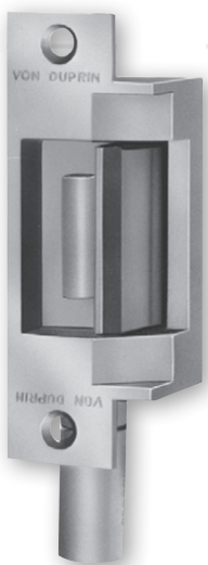
Von Duprin electric strikes across the 5100, 6100, 6200, and 6300 product lines share the same basic schematic diagram but have series-specific differences in terminal configuration, voltage options, and monitoring capabilities that affect the wiring before the installation begins.
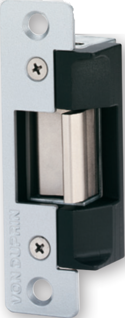
Von Duprin 5100 Series
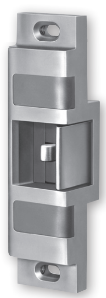
Von Duprin 6100 Series
Von Duprin 6200 Series

Von Duprin 6300 Series
Voltage: 12VDC or 24VDC (specify at order)
Monitoring: No internal monitoring switch
Terminals: Two-terminal solenoid power only
Notes: Cylindrical and mortise compatible. Solenoid not field-replaceable.
Voltage: 12VDC or 24VDC (specify at order)
Monitoring: No internal DS switch
Terminals: Two-terminal solenoid power only
Notes: Heavy-duty rim exit device applications. Solenoid not field-replaceable.
Voltage: 24VDC standard (12VDC and AC with SO kits)
Monitoring: Optional DS dual switch (two SPDT contacts)
Terminals: Power terminals plus optional DS monitoring terminals
Notes: External solenoid canister replaces in under 5 minutes. SO12/SO24 rectifier kits available for AC sources. Most versatile series for commercial retrofit.
Voltage: 24VDC standard
Monitoring: DS dual switch standard
Terminals: Power terminals plus dual switch monitoring terminals
Notes: Heavy-duty stainless steel for high-security and exterior applications. Monitoring is standard, not optional. Same SO rectifier kit compatibility as 6200 for AC applications.
Browse Von Duprin electric strike series parts and diagrams at SecurityParts.com. For parts specific to each series, the interactive parts diagram on each model page shows every terminal, component, and part number specific to that product.
Common Wiring Mistakes and How to Avoid Them
Sharing the Access Panel Power Supply with the Electric Strike
Most access control panels include a low-current internal power supply designed for the panel board and credential verification components. This internal supply is not designed to also power the solenoid. An electric strike solenoid draws 300mA to 500mA on activation, which can cause the panel's internal supply to sag, resetting the panel firmware or causing erratic relay behavior. Always power the electric strike from a dedicated, appropriately rated power supply that is separate from the panel's internal supply.
Running AC Power to a DC-Rated Solenoid Without a Rectifier
This is the single most common installation error in commercial electric strike work. The buzzing sound it produces is unmistakable and the solenoid damage it causes is rapid. If AC is the only power source available, install an SO12 or SO24 rectifier kit in-line before the strike terminals. If a Von Duprin rectifier kit is not the right fit for the installation, a standard full-wave bridge rectifier module with appropriate voltage and current ratings performs the same function.
Reversing the Back EMF Diode Polarity
A diode installed with reversed polarity (anode at positive terminal, cathode at negative) becomes a short circuit when the solenoid energizes. This blows the access panel's output fuse or destroys the output transistor within the first access grant. Always orient the diode with the cathode banded end toward the positive terminal. If uncertain, test the installation with a multimeter set to diode mode before powering the circuit.
Connecting Monitoring Switch Wires to Power Terminals
DS monitoring switches inside the strike operate at the low-current levels used by the access panel's input circuit, typically milliampere-level signals. The solenoid power terminals carry hundreds of milliamperes. Connecting the monitoring wires to the power terminals sends full solenoid current through the monitoring switch, burning the switch immediately and potentially damaging the access panel's input circuit. Always identify monitoring terminals separately from power terminals before making any connections.
Using Undersized Wire on Long Runs
An installation that tests correctly at 50 feet of wire and then fails intermittently at 150 feet is almost always a voltage drop problem caused by undersized wire gauge. The solenoid actuates on the bench, actuates correctly during initial commissioning, and then begins to fail intermittently as the solenoid winding heats up and its resistance increases slightly. Calculate voltage drop before selecting wire gauge. Use 18 AWG for runs over 75 feet on 12VDC systems.
Why Choose SecurityParts.com for Von Duprin Electric Strike Parts
SecurityParts.com has supplied commercial door hardware parts since 2001. Our Von Duprin electric strike catalog covers the complete 5100, 6100, 6200, and 6300 Series with model-specific interactive parts diagrams on every product page. The interactive diagram lets you visually confirm the exact solenoid, keeper, monitoring switch, faceplate, or rectifier kit before placing the order, eliminating most wrong-part returns before they happen.
The Von Duprin 6200 Series solenoid canister is externally mounted and replaces in under five minutes without removing the strike from the frame. This is the repair that saves hours on high-traffic commercial openings where full unit removal and frame patching is the only alternative on many legacy installations. SecurityParts.com stocks solenoid canisters, SO12 and SO24 rectifier kits, DS monitoring switch components, keepers, and faceplates for the complete Von Duprin electric strike range.
Browse Von Duprin electric strike parts and diagrams by series, read the electric strike components and failure diagnosis guide, browse the complete Von Duprin parts catalog, or see all SecurityParts.com commercial door hardware parts. Call 845-935-0301 or visit the SecurityParts.com contact page for pre-order wiring and specification support.