Trusted Since 2001





Quick Answer
Security Parts stocks 27 replacement components for the Adams Rite 7100 Series electric strike. The most frequently replaced parts are the 29-0250 solenoid (five voltage variants), the 27-0085 latch, the 27-0086 blocking arm, and the 31-0092 microswitch. Before ordering the solenoid, confirm both the voltage and the duty mode (continuous or intermittent), because AC intermittent solenoids cannot be used in fail-safe applications. The 7100 Series is field reversible between fail-safe and fail-secure. Do not lubricate the strike mechanism. All 27 parts are genuine OEM components available to order individually. Call 845-935-0301 to confirm specifications before placing an order.
What Is the Adams Rite 7100 Series Electric Strike?
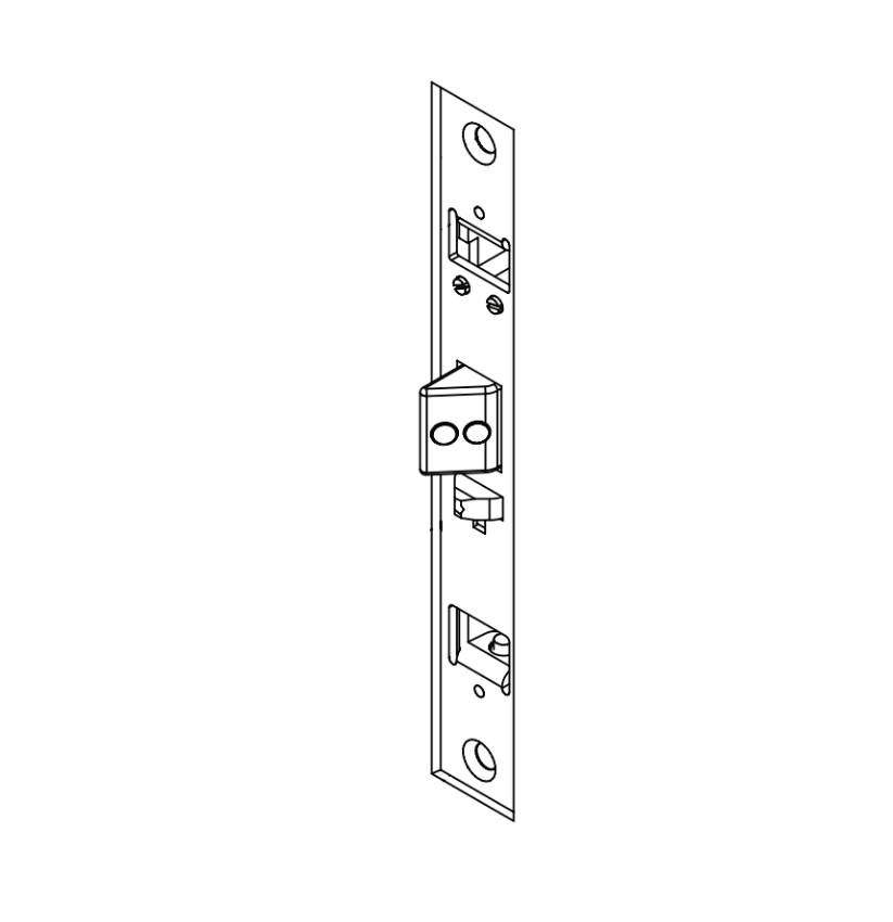
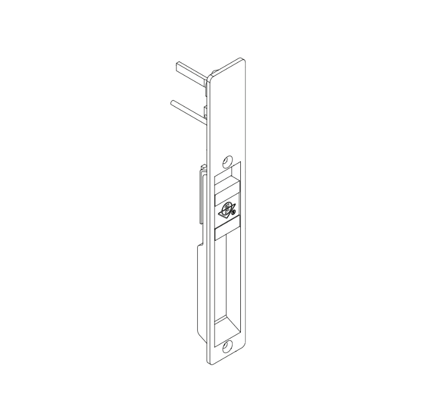
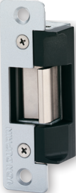
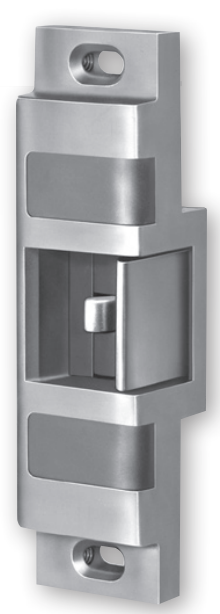
The Adams Rite 7100 Series is a family of electric strikes designed for use with Adams Rite deadlatches and cylindrical locksets on aluminum, hollow metal, and wood door applications. The strike provides remote electrical control of the door by releasing the latch bolt without requiring anyone to operate the lockset itself. When the solenoid is energized, it moves a shuttle which releases the blocking arm, allowing the jaw to tilt out of position so the door can open.
The 7100 is UL 1034 burglary-resistant listed and UL 294 listed. It is designed for latchbolts with a projection of 1/2 inch to 5/8 inch. The bolt retaining jaw is stainless steel. The mechanism fits into aluminum jamb or door sections as shallow as 1-5/8 inches deep, which makes it suited for narrow profile aluminum storefront frames where space is limited.
The 7100 Series also fits the existing frame preparation for the discontinued Adams Rite 7000, 7500, and 7800 electric strike series. If an older installation is being serviced and the existing strike has failed, the 7100 uses the same prep and is the current replacement option.
For a broader overview of electric strike families at Security Parts, see the electric strikes parts and diagrams page. For Adams Rite exit device parts, see the Adams Rite 41 series parts guide and the Adams Rite parts guide.
What Is the Difference Between the Adams Rite 7100 and 7101?
The 7100 and 7101 share the same internal mechanism and the same replacement parts for the solenoid, latch, blocking arm, shuttle, springs, and monitoring components. The difference is the faceplate profile and the application.
| Model | Faceplate | Application | Lip Extension Available | Monitoring Available |
|---|---|---|---|---|
| 7100 | Flat | Aluminum jambs, hollow metal, wood | Yes | Yes |
| 7101 | Radius | Aluminum stiles -- inactive leaf in glass door pairs | No | No |
The 7101 radius faceplate is designed to match the curved nose on the inactive leaf in a pair of narrow stile glass doors. If monitoring or a lip extension is required, the 7101 is not the correct model. Confirm the installed model number before ordering any subcover or faceplate replacement.
Is the Adams Rite 7100 Electric Strike Field Reversible?
Yes. The Adams Rite 7100 Series is field selectable between fail-safe and fail-secure operation at the time of installation. The conversion is performed by repositioning the shuttle return spring and reversing the direction of the solenoid inside the case. No additional components or specialized tools are required for the conversion itself.
What Is the Difference Between Fail-Safe and Fail-Secure on the Adams Rite 7100?
These two modes define what happens to the door when power is lost or the access control signal drops.
| Mode | Power State | Strike State | Door State | Solenoid Duty Requirement |
|---|---|---|---|---|
| Fail-Secure | Power off | Locked | Cannot be opened from outside | Intermittent or continuous |
| Fail-Safe | Power off | Unlocked | Can be pushed open | Continuous duty only |
Can an AC Intermittent Solenoid Be Used for Fail-Safe Operation?
No. This is one of the most important ordering rules for the 7100 Series and one that causes significant field problems when ignored. In a fail-safe configuration, the solenoid must remain energized continuously to keep the door locked. An AC intermittent solenoid is not rated for continuous duty and will overheat if used in this way. Fail-safe applications require a continuous duty solenoid, either DC continuous or AC continuous (with a rectifier). If the existing installation has an intermittent duty solenoid, it can only be used in fail-secure mode. To convert to fail-safe operation, the solenoid must be replaced with a continuous duty variant alongside the mechanical conversion.
Why Does My Adams Rite 7100 Electric Strike Make a Buzzing Sound?
The buzzing sound is normal and expected behavior for AC intermittent solenoid variants. Alternating current regularly reverses direction, which causes audible vibration in the solenoid coil during operation. DC continuous solenoids operate silently.
If the installed solenoid is a DC unit and the strike is producing a buzzing or clicking sound, that is not expected behavior. In that case, inspect the wiring connections and the power supply output before assuming solenoid failure. A buzzing DC solenoid may be receiving AC power from an incorrectly specified power supply.
If the installation requires silent operation, specify a DC continuous solenoid variant. The appropriate options are the 29-0250-24DCC, 29-0250-16DCC, or 29-0250-12DCC depending on the system voltage.
Should I Lubricate the Adams Rite 7100 Electric Strike?
No. Adams Rite installation documentation for the 7100 Series explicitly states: DO NOT LUBRICATE STRIKE. This is a common maintenance mistake, particularly on installations where technicians follow the same procedure they use for mechanical locksets. The 7100 internal mechanism is designed to operate dry. Applying any lubricant to the internal shuttle, blocking arm, latch arm, or spring components will attract dust and debris over time, causing the mechanism to bind, slow down, or fail to release consistently. If a 7100 is releasing sluggishly or inconsistently, the cause is typically a worn part rather than inadequate lubrication.
Does the Adams Rite 7100 Replace the 7000, 7500, or 7800 Series?
Yes. The Adams Rite 7100 Series fits the existing frame preparation for the discontinued 7000, 7500, and 7800 electric strike series. If a facility is servicing an older installation where one of those discontinued series has failed and is no longer available for replacement, the 7100 uses the same frame prep and is the current successor. This is a significant practical detail for maintenance professionals managing older commercial buildings with legacy Adams Rite hardware.
When replacing a discontinued series strike with a 7100, confirm the voltage and mode required by the access control system before ordering the solenoid variant.
What Latch Bolt Projection Does the Adams Rite 7100 Require?
The Adams Rite 7100 is designed for use with latchbolts that have a projection between 1/2 inch and 5/8 inch. It accepts the bolt from any Adams Rite 4500 Series or 4900 Series deadlatch, and from cylindrical locksets with a latchbolt within this projection range. Latchbolts with a projection outside this range will not seat and release correctly in the strike pocket. Confirm the latchbolt projection of the installed lockset before specifying the 7100 for a new installation or before troubleshooting repeated failure-to-latch issues on an existing one.
The strike opening is 5/8 inch x 1-7/16 inch x 1/2 inch deep. The bolt retaining jaw is stainless steel.
Is Form C Monitoring Available on All Adams Rite 7100 Series Models?
No. The two Form C monitoring switches are available on most 7100 Series models but are not available on the 7130, 7131, or 7140. If an application requires monitoring and a 7130, 7131, or 7140 is currently installed, monitoring cannot be added to that strike body. A different model will need to be specified for the monitoring function.
The two Form C switches on a monitored 7100 Series strike serve two different functions: one switch is activated by latchbolt penetration of the strike, and the other indicates whether the strike jaw is locked or unlocked by the solenoid. Both switches provide dry contacts. All unused monitoring leads must be insulated before the strike is placed in service.
What Are the Monitoring Wire Colors on the Adams Rite 7100?
On the monitored version of the Adams Rite 7100, the wire color coding as specified in Adams Rite installation documentation is as follows.
| Wire Color | Function |
|---|---|
| Black | Common |
| White | Normally Open (NO) |
| Red | Normally Closed (NC) |
The solenoid wires are not polarized. All unused monitoring leads must be insulated. This wiring information is needed when replacing the microswitch assembly or reconnecting a monitored 7100 strike after service.
What Adams Rite 7100 Replacement Parts Are Available?
All 27 Adams Rite 7100 Series replacement components stocked at Security Parts are listed below. Each is a genuine OEM Adams Rite component available to order individually.
| # | Part Number | Component Name | Notes |
|---|---|---|---|
| 1 | 29-0250-24DCC | Solenoid, 24 VDC Continuous | Silent; fail-safe or fail-secure |
| 2 | 29-0250-16DCC | Solenoid, 16 VDC Continuous | Silent; fail-safe or fail-secure |
| 3 | 29-0250-16ACI | Solenoid, 16 VAC Intermittent | Buzzes; fail-secure only |
| 4 | 29-0250-12DCC | Solenoid, 12VDC/24VAC | Silent; fail-safe or fail-secure |
| 5 | 29-0250-12ACI | Solenoid, 12 VAC Intermittent | Buzzes; fail-secure only |
| 6 | 27-0085 | Latch | No specification required |
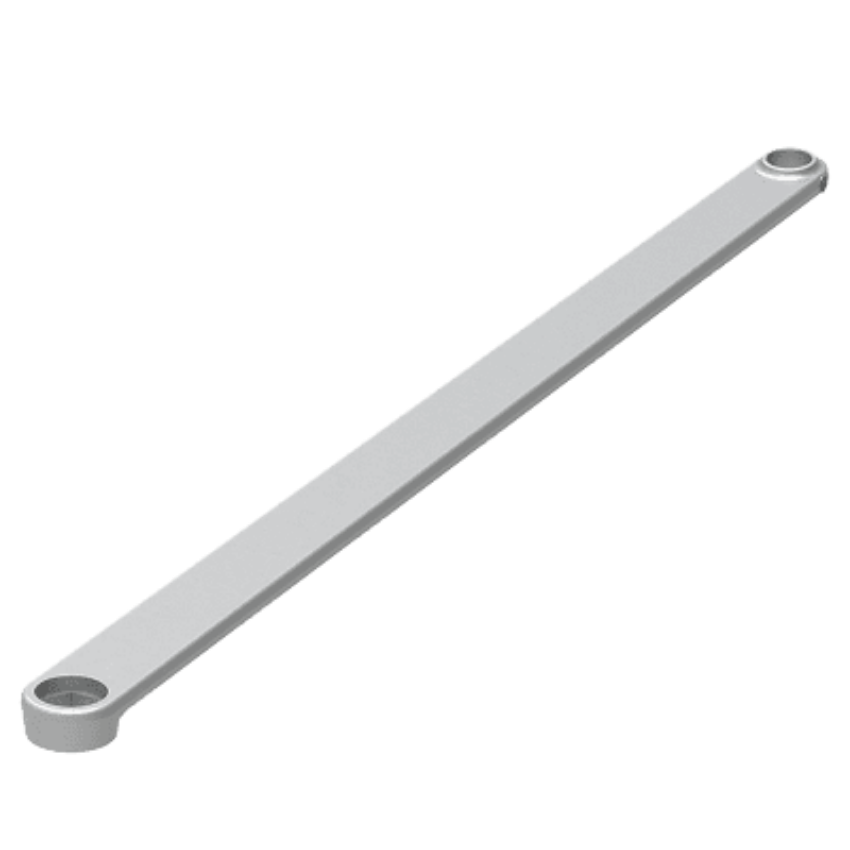
| 7 | 27-0086 | Blocking Arm | No specification required |
| 8 | 23-0356 | Shuttle | No specification required |
| 9 | 28-0150-MP | Shuttle Return Spring | No specification required |
| 10 | 28-0151-MP | Block Arm Return Spring | No specification required |
| 11 | 23-0349 | Bolt Switch Actuator | No specification required |
| 12 | 31-0092 | Microswitch | No specification required |
| 13 | 22-0713 | Switch Plate | No specification required |
| 14 | 22-0657 | Solenoid Retainer Plate | No specification required |
| 15 | 26-0170 | Plunger | No specification required |
| 16 | 22-0698-MP | Nut Plate | No specification required |
| 17 | 26-0214-MP | Shoulder Screw | No specification required |
| 18 | 29-0341-MP | Phillips Hex Head Screw #2 x 5/8 | No specification required |
| 19 | 29-0342-MP | Phillips Hex Head Screw #2 x 3/8 | No specification required |
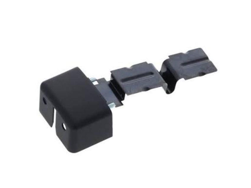
| 20 | 23-0350 | 1/2-Inch Back Cover | Confirm installed size before ordering |
| 21 | 23-0351 | 3/4-Inch Back Cover | Confirm installed size before ordering |
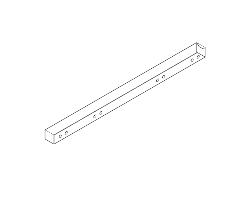
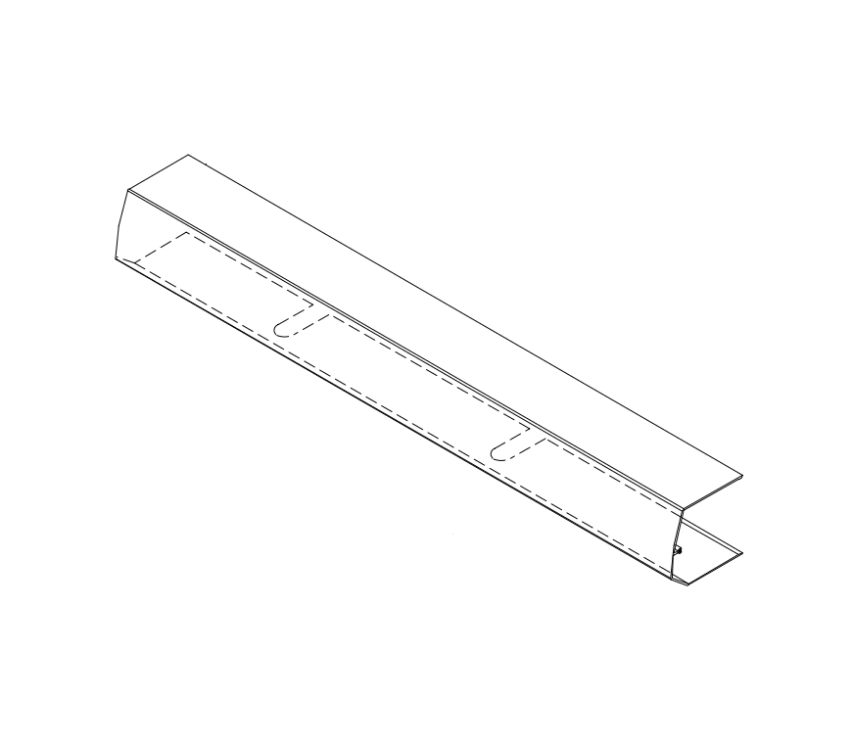
| 22 | 23-0443 | 1/2-Inch Flat Subcover | For 7100, 7110, 7111, 7130, 7140 |
| 23 | 23-0444 | 1/2-Inch Radius Subcover | For 7101, 7131 |
| 24 | 23-0445 | 3/4-Inch Subcover | For 7160, 7170 |
| 25 | 91-0171-01 | Subcover Lip Extension Kit | For 7100, 7110, 7111, 7130, 7140; 1-1/2 in. centerline to jamb edge; not available for 7101 |
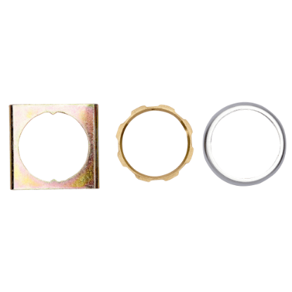
| 26 | 91-0099 | Cylinder Kit | Cylinder dogging C; includes anti-rotation ring, locking nut, locking nut tool |
| 27 | 31-0265-01-IP | Dogging Assembly | No specification required |
Solenoid Variants: Which 29-0250 Do I Order?
The solenoid is the electrical actuator at the core of the 7100 strike. It moves the shuttle, which in turn releases the blocking arm and allows the jaw to tilt so the door can open. The Adams Rite 7100 uses the 29-0250 solenoid family. Five variants are available. The correct choice depends on three things: the system voltage, whether the current is AC or DC, and the operating mode required by the application.
Which Solenoid Variant Buzzes and Which Is Silent?
DC continuous solenoids operate silently. AC intermittent solenoids produce an audible buzz during operation because alternating current reverses direction repeatedly. This is normal behavior for an AC solenoid and is not a fault. If silent operation is required, specify a DC continuous variant.
| Part Number | Voltage | Duty Mode | Sound | Fail Mode | Order |
|---|---|---|---|---|---|
| 29-0250-24DCC | 24 VDC | Continuous | Silent | Fail-safe or fail-secure | View Part |
| 29-0250-16DCC | 16 VDC | Continuous | Silent | Fail-safe or fail-secure | View Part |
| 29-0250-16ACI | 16 VAC | Intermittent | Buzzes | Fail-secure only | View Part |
| 29-0250-12DCC | 12 VDC / 24 VAC | Continuous | Silent | Fail-safe or fail-secure | View Part |
| 29-0250-12ACI | 12 VAC | Intermittent | Buzzes | Fail-secure only | View Part |
Mechanical Components: Latch, Blocking Arm, Shuttle, and Springs
What Does the Adams Rite 7100 Latch Do?
The 27-0085 latch is the pivoting jaw component that seats the door lockset latchbolt when the door closes. It holds the latchbolt in the strike pocket until the solenoid releases the blocking arm. A worn or damaged latch may cause the door to fail to latch on closing or may bind during release. Inspect the latch for wear at the contact surfaces and pivot point when the door is slow to latch or the strike releases inconsistently.
What Does the Adams Rite 7100 Blocking Arm Do?
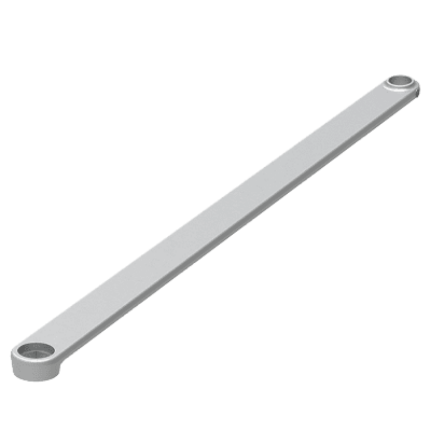
The 27-0086 blocking arm is the component that holds the latch jaw in the locked position. When the solenoid energizes and moves the shuttle, the blocking arm tip releases from the latch arm notch and the jaw is free to tilt. The 28-0151-MP block arm return spring drives the blocking arm back to the locked position after each release cycle. A bent or worn blocking arm tip will cause the strike to release even when the solenoid is not energized.
What Does the Adams Rite 7100 Shuttle Do?
The 23-0356 shuttle transfers solenoid motion to the blocking arm. When the solenoid energizes, the plunger moves the shuttle, which in turn releases the blocking arm tip from the latch arm notch. The 28-0150-MP shuttle return spring resets the shuttle to its original position after each activation. During a fail-secure to fail-safe field conversion, the shuttle return spring position is one of the two components that must be repositioned. Replacing the shuttle without also checking the return spring position after a mode conversion will result in incorrect operation.
When Should the Return Springs Be Replaced?
Inspect both the shuttle return spring (28-0150-MP) and the block arm return spring (28-0151-MP) whenever the solenoid or shuttle is replaced. A fatigued return spring may not provide enough force to reset the mechanism fully, which causes the blocking arm to partially re-engage or the shuttle to sit in an intermediate position. This creates intermittent locking failures that are difficult to diagnose without inspecting the spring condition directly. On high-cycle installations, replacing both springs at the same time as the solenoid is a standard preventive step.
Electrical Monitoring: Microswitch, Switch Plate, and Bolt Switch Actuator
What Does the Adams Rite 7100 Microswitch Do?
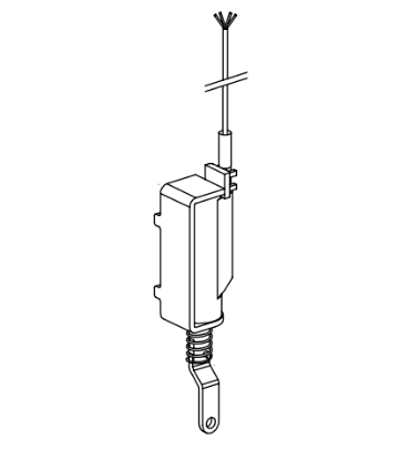
The 31-0092 microswitch is triggered by the bolt switch actuator to send a status signal to the access control or alarm panel. On monitored 7100 strikes, two switches are present: one activated by latchbolt penetration of the strike, and one indicating whether the jaw is locked or unlocked. When the microswitch fails, the access control panel receives incorrect or absent status signals. Replace the microswitch when wiring and power supply have been confirmed correct but status signals are still unreliable.
What Does the Adams Rite 7100 Bolt Switch Actuator Do?
The 23-0349 bolt switch actuator is the mechanical link that physically triggers the microswitch when the latch bolt position changes. A worn or misaligned actuator will cause intermittent or absent status signaling even when the microswitch itself is functional. Inspect the actuator alongside the microswitch whenever monitoring function is unreliable.
Solenoid Support: Retainer Plate, Plunger, and Nut Plate
Three components support the solenoid assembly within the strike body. Each is ordered individually and requires no specification.
- 22-0657 Solenoid Retainer Plate: Secures the solenoid in its correct position inside the strike body. A displaced solenoid does not transfer force to the shuttle correctly, resulting in weak or absent release. Replace the retainer plate alongside the solenoid if the plate shows wear or deformation.
- 26-0170 Plunger: The solenoid output component that directly contacts and moves the shuttle when the solenoid energizes. A worn plunger reduces force transfer to the shuttle. When a solenoid replacement does not resolve a weak release symptom, inspect the plunger before ordering additional parts.
- 22-0698-MP Nut Plate: Provides a threaded fastening point within the strike body. A stripped nut plate will prevent correct reassembly after service.
Subcover Selection: Which Subcover Does the Adams Rite 7100 Use?
Subcover selection depends on the specific 7100 Series model number installed. Confirm the model number on the strike body before ordering.
| Part Number | Description | Compatible Models |
|---|---|---|
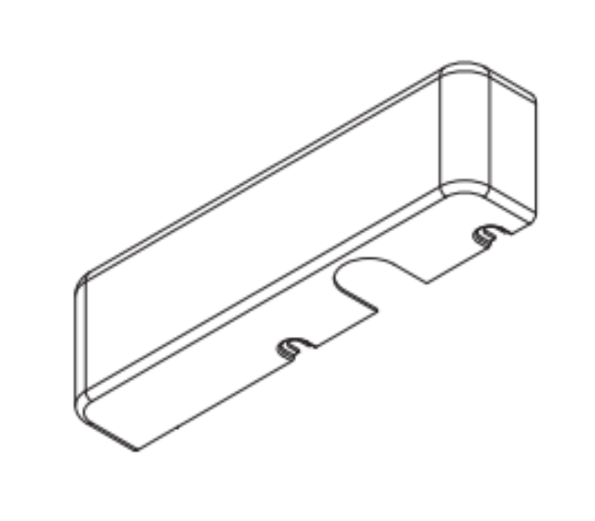
| 23-0443 | 1/2-Inch Flat Subcover | 7100, 7110, 7111, 7130, 7140 |
| 23-0444 | 1/2-Inch Radius Subcover | 7101, 7131 |
| 23-0445 | 3/4-Inch Subcover | 7160, 7170 |
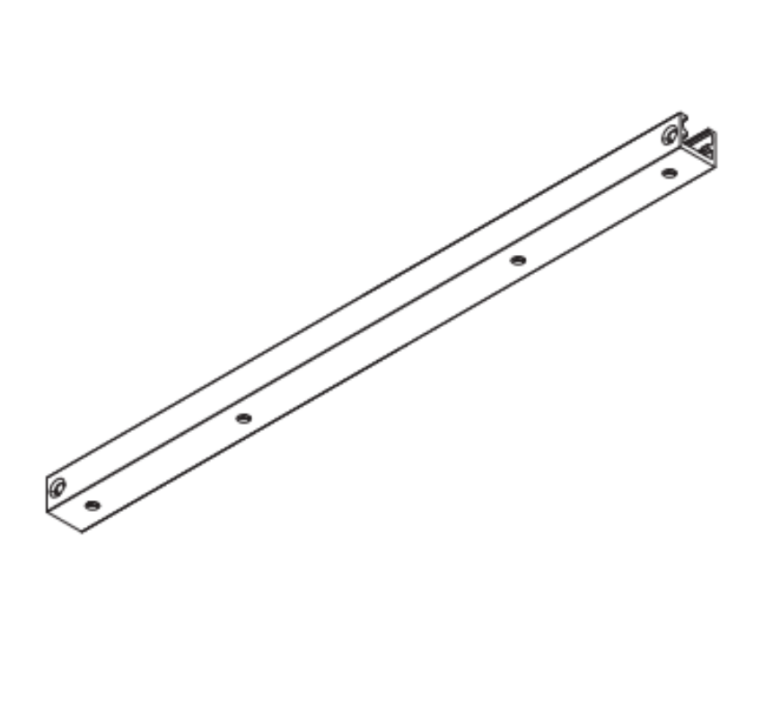
| 91-0171-01 | Subcover Lip Extension Kit (1-1/2 in. centerline to jamb edge) | 7100, 7110, 7111, 7130, 7140 only (not 7101) |
When Is the Lip Extension Kit Needed?
The standard lip on the 7100 is sized for a 1-3/4-inch thick door that closes flush with the jamb edge. Where the door thickness or jamb shape differs from this standard relationship, a lip extension is needed. Typical applications include center-hung doors and thick doors where the door centerline to jamb edge dimension exceeds the standard. The 91-0171-01 subcover lip extension kit provides a 1-1/2-inch dimension from the door centerline to the jamb edge. Lip extensions are not available for the 7101 or 7131 models.
Back Cover Selection: 1/2-Inch vs 3/4-Inch
| Part Number | Description |
|---|---|
| 23-0350 | 1/2-Inch Back Cover |
| 23-0351 | 3/4-Inch Back Cover |
The back cover size corresponds to the frame pocket depth of the installed strike. Measure the existing back cover or confirm the installed model number before ordering to avoid the wrong size.
How to Identify the Correct Adams Rite 7100 Part Before Ordering
| What to Confirm | Applies To |
|---|---|
| System voltage (12V, 16V, or 24V) | 29-0250 solenoid family (all 5 variants) |
| Current type (AC or DC) and duty mode (continuous or intermittent) | 29-0250 solenoid family; intermittent = fail-secure only |
| Operating mode (fail-safe or fail-secure) | Solenoid selection; fail-safe requires continuous duty |
| 7100 Series model number (7100, 7101, 7110, 7111, 7130, 7131, 7140, 7160, 7170) | Subcover selection (23-0443, 23-0444, 23-0445) |
| Back cover size (1/2-inch or 3/4-inch) | 23-0350 and 23-0351 back covers |
| Whether lip extension is needed (door thickness or jamb shape) | 91-0171-01 subcover lip extension kit |
| Whether monitoring is present (7130/7131/7140 do not support monitoring) | 31-0092 microswitch, 23-0349 bolt switch actuator, 22-0713 switch plate |
Troubleshooting Adams Rite 7100 Electric Strike Problems
| Symptom | Check First | Parts to Inspect or Replace |
|---|---|---|
| Strike does not release when energized | Confirm voltage at solenoid terminals matches solenoid rating | 29-0250 solenoid, 26-0170 plunger, 23-0356 shuttle |
| Strike buzzes during operation | Confirm solenoid is AC intermittent (expected) or DC (problem) | Replace with DC continuous variant if silent operation required |
| Door does not re-latch after release | Inspect shuttle and blocking arm return travel | 28-0150-MP shuttle return spring, 28-0151-MP block arm return spring, 27-0086 blocking arm |
| Status monitoring signal absent or incorrect | Inspect wiring connections; confirm wire color coding (Black=Common, White=NO, Red=NC) | 31-0092 microswitch, 23-0349 bolt switch actuator, 22-0713 switch plate |
| Weak or sluggish release | Confirm correct voltage; do not lubricate mechanism | 29-0250 solenoid, 26-0170 plunger, 22-0657 solenoid retainer plate |
| Strike releases without power applied (fail-secure) | Inspect blocking arm tip against latch arm notch; confirm shuttle spring is in correct position | 27-0086 blocking arm, 28-0151-MP block arm return spring, 23-0356 shuttle |
| Fail-safe solenoid overheating | Confirm solenoid is continuous duty -- AC intermittent cannot run continuously | Replace with correct continuous duty 29-0250 variant |
How Deep Must the Frame Pocket Be for the Adams Rite 7100?
The Adams Rite 7100 mechanism fits into aluminum jamb or door sections as shallow as 1-5/8 inches deep. This compact depth is what makes the 7100 practical for narrow profile aluminum storefront frames where hollow metal or wood frame alternatives would not fit. When retrofitting an older opening or installing on an unusual frame profile, measure the available pocket depth before ordering to confirm the 7100 fits without requiring frame modification.
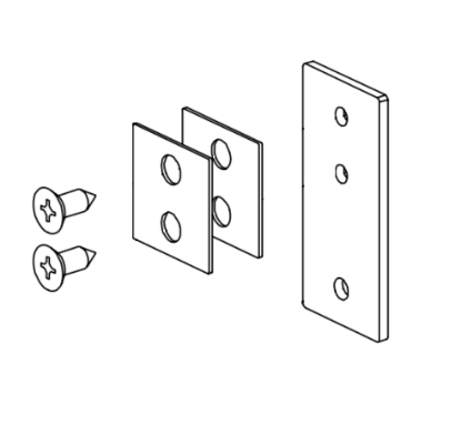
The full case dimensions are approximately 1 inch wide by 3-3/8 inches long by 1-5/8 inches deep. The standard package includes mounting screws, mounting clips, and adhesive shims to accommodate jamb or stile extrusion thickness greater or less than the nominal 1/8-inch. These shims allow the strike to sit flush against the frame regardless of minor extrusion thickness variation without requiring recutting the frame pocket.
Adams Rite 7100 Dogging Components: Cylinder Kit and Dogging Assembly
What Is the Adams Rite 91-0099 Cylinder Kit Used For?
The 91-0099 cylinder kit is used for cylinder dogging C applications. It is a service kit, not a complete cylinder. The kit includes the anti-rotation ring, locking nut, and locking nut tool. It is ordered when the cylinder dogging mounting hardware needs replacement rather than when the cylinder itself needs replacement. Confirm the dogging configuration of the installation before ordering this kit.
What Is the Adams Rite 31-0265-01-IP Dogging Assembly?
The 31-0265-01-IP dogging assembly is a genuine OEM replacement component for applicable dogging configurations. No specification is required at the time of order. Replace the complete dogging assembly when the dogging function is not holding correctly or when the assembly is physically damaged during service.
Adams Rite OEM Warranty on 7100 Series Parts
All Adams Rite 7100 Series parts stocked at Security Parts are genuine OEM components covered by Adams Rite manufacturer warranties. The warranty periods from the date of manufacture are as follows.
- 10 years on all mechanical products.
- 5 years on electromechanical categories including electric strikes, exit devices, deadlocks, deadlatches, trims, and power supply accessories. This covers the 29-0250 solenoid family, the 31-0092 microswitch, the 23-0349 bolt switch actuator, and all other electromechanical 7100 Series components.
- 3 years on specific access control products including the DL100 Aperio Wireless Deadlatch and 3090-150.
Warranty coverage applies to genuine OEM parts only. Ordering genuine OEM parts from Security Parts ensures that warranty coverage is not voided by aftermarket substitution. If documentation of a specific component's warranty period is needed for a facility compliance record, confirm the part number and manufacturing date at the time of purchase.
Why Order Adams Rite 7100 Parts from Security Parts?
Security Parts has supplied commercial door hardware components to locksmiths, glaziers, facilities managers, general contractors, and security integrators since 2001. Every Adams Rite 7100 Series part stocked at Security Parts is a genuine OEM component. All 27 components listed in this guide are verified in stock for immediate ordering.
Ordering genuine OEM components matters more for electric strike parts than it does for many other hardware categories. An aftermarket solenoid may appear identical to the OEM part physically but differ in coil resistance, pull force, or duty cycle rating in ways that are not visible during installation. These differences only become apparent over time, typically showing up as intermittent release failures, overheating in fail-safe applications, or premature solenoid wear on high-cycle doors.
Pre-order part identification support is available at 845-935-0301. If the model number label on the installed strike body is unreadable, Security Parts can help identify the correct subcover, back cover, and solenoid variant from the installation details before an order is placed. If an older installation needs to be converted from the discontinued 7000, 7500, or 7800 series to the 7100, Security Parts can confirm compatibility before the order is placed.
For related Adams Rite hardware, see the Adams Rite 41 series parts guide and the Adams Rite parts guide. For electric strike installation guidance, see the how to install an electric strike guide.
About Security Parts
Security Parts has supplied genuine OEM commercial door hardware components to locksmiths, glaziers, facilities managers, general contractors, and security integrators since 2001. All 27 Adams Rite 7100 Series replacement parts listed in this guide are stocked and verified for immediate ordering. Security Parts carries OEM Adams Rite components and will flag any compatible aftermarket alternative before an order is placed.
Call 845-935-0301 for pre-order part identification, voltage confirmation, model matching, or guidance on converting an existing installation from fail-secure to fail-safe before ordering parts.
Related Resources at Security Parts
- Electric Strikes Parts and Diagrams
- Adams Rite 41 Series Parts Guide
- Adams Rite Parts Guide
- Exit Devices Parts and Diagrams
- How to Install an Electric Strike
- What Is Delayed Egress
Adams Rite 7100 Electric Strike: Key Ordering Rules Summary
Before placing any order for Adams Rite 7100 Series parts, review these rules. Each one reflects a common ordering mistake that causes the wrong part to arrive.
- AC intermittent solenoids are rated for fail-secure mode only. Never specify an AC intermittent solenoid for a fail-safe installation.
- Fail-safe applications require a continuous duty solenoid: 29-0250-24DCC, 29-0250-16DCC, or 29-0250-12DCC.
- Subcover selection depends on the model number, not just the series name. A 7101 uses a different subcover (23-0444) than a 7100 (23-0443).
- Lip extensions are not available for the 7101 or 7131 models.
- Monitoring components (microswitch, bolt switch actuator, switch plate) are not available for 7130, 7131, or 7140 models.
- Do not lubricate any internal component of the 7100 mechanism.
- All unused monitoring leads must be insulated before the strike is placed in service.
- When replacing a discontinued 7000, 7500, or 7800 series strike, the 7100 fits the existing frame preparation.
Call Security Parts at 845-935-0301 for pre-order identification support on any of the above. All 27 Adams Rite 7100 Series replacement components are stocked and available to order individually.