 Trusted Since 2001





An electromagnetic lock looks like the simplest device on a commercial opening. It is a coil, a steel plate and two wires. Most of the service calls it generates come from a handful of parts and settings that almost nobody writes down, so this guide names every component, explains how holding force is actually rated, sets out the egress rules the lock has to meet, and gives you a symptom to cause table for the day it stops holding.
Quick Summary
An electromagnetic lock is a coil in a steel housing that is mounted to the frame head, plus a steel armature plate bolted to the door. Energize the coil and the magnetic bond between the two holds the door shut. Cut the current and the bond disappears, which is why every direct pull maglock is fail safe by design.
Key points
- Holding force is not about door weight. The hinges carry the weight. The rating describes the pull needed to break the magnetic bond.
- The armature plate is meant to float slightly. Over tightening the sex bolt stops it seating flush and is the most common install fault.
- Two release methods are recognised by the model codes. Sensor release and door hardware release. Section numbers move between code editions, so confirm with your authority having jurisdiction.
- A maglock does not replace positive latching on a fire rated opening. The latch stays, and the lock itself has to be labeled for fire door use.
- Slow release is usually a diode, not magnetism. Fit the suppression the manufacturer calls for and check whether the lock already has it inside.
- Use 24 VDC on long runs. The same lock draws roughly half the current, so voltage drop hurts you far less.
| Question | Short answer |
|---|---|
| What holds the door | Magnetic bond between an energized coil and a steel armature plate |
| Typical single door ratings | Commonly supplied at 600 lb and 1,200 lb, with higher and lower tiers available |
| Supply | Filtered, regulated DC. Dual voltage units are selected on a jumper or switch inside the wiring compartment |
| Fail state | Fail safe only. No power means no hold |
| Needs a latch as well | Yes on any fire rated opening, and often on egress doors depending on the release method used |
| Most common fault | Misalignment or an over tightened armature, followed by power supply problems |
In This Guide
- What is an electromagnetic lock and how does it work?
- What are the parts of an electromagnetic lock?
- How is holding force rated, and does door weight matter?
- Which bracket do you need: L, Z, U or header plate?
- How much power does a maglock draw, and should you wire 12V or 24V?
- What egress rules does an electromagnetic lock have to meet?
- Can you put an electromagnetic lock on a fire rated door?
- Why is my maglock not holding or not releasing?
- When is a maglock the wrong choice?
- About the author
What Is an Electromagnetic Lock and How Does It Work?
An electromagnetic lock is an electrically operated holding device with no latch, no bolt and no keyway. Current through a coil magnetizes a stack of ferrous plates inside the lock housing. A machined steel armature plate on the door is drawn against the machined face of the housing, and the bond between the two resists anyone pulling the door open.
The behaviour that matters is what happens when the current stops. The bond collapses immediately and the door is free. That single property is why maglocks are treated as a special locking arrangement in the egress sections of the model codes rather than as ordinary door hardware.
Two families exist. A direct pull maglock resists force pulling straight off the magnet face and suits a single swinging door. A shear lock sets locating pins or tabs into recesses in the magnet face, so the load acts across the joint instead of straight off it. That mechanical interlock is what lets shear locks work on double acting doors and on sliding doors, where a header mounted direct pull magnet will not hold.
What Are the Parts of an Electromagnetic Lock?
Most published descriptions stop at "a magnet and a plate". A service tech ordering a replacement needs the rest of the stack, because the mounting hardware fails far more often than the coil does.
| Part | What it does | Why it matters on a service call |
|---|---|---|
| Lock housing and coil | Stacked ferrous plates wound with copper, potted in a non ferrous fill, with a machined face | Rarely the failed part. Suspect it only after power and alignment check out |
| Armature plate | Machined steel plate on the door that the magnet bonds to | Must sit flat and cover the magnet poles. Offset or partial contact loses holding force fast |
| Sex bolt and nut | Through bolts the armature to the door | The adjustment that decides whether the plate can seat. See below |
| Rubber washer | Sits in the armature fastener stack | Allows the plate limited movement so it can pivot flush against the magnet |
| Steel washer and spacers | Set standoff and spread load through the door | Thicker doors need the correct kit. The wrong stack leaves the plate proud or buried |
| Anti rotation pins | Short pins driven into the armature face | Stop the plate spinning on its bolt and drifting out of alignment |
| Mounting brackets | L, Z, U or header plate, matched to door swing and frame | Brand and model specific. Rarely interchangeable between makes |
| Filler plate or angle bracket | Creates a flat mounting surface where the frame stop is shallow | Needed when the header stop is too narrow for direct mounting |
| Bond sensor | Reports that the magnet and armature are actually bonded | The only accessory that tells you the door is really held |
| Door position switch | Reports door closed or open | Often wired in series so the lock cannot energize before the door settles |
| Status LED | Visual indication at the lock | Useful first check, but it shows the board state, not the bond |
| Suppression component | Diode or metal oxide varistor across the coil | Choice of part changes how fast the lock releases. Covered below |
Why the Armature Plate Has to Float
Manufacturer instructions describe the armature as designed to pivot slightly so it can compensate for reasonable misalignment. That pivot is the whole point of the rubber washer in the fastener stack. Torque the sex bolt down hard and the plate becomes rigid, which means it can no longer self align against the magnet face.
The field symptom is a lock that reports energized but can be pulled open by hand. Technicians commonly back the armature bolt off between half a turn and a full turn so the plate can snap flat. Treat that as trade practice consistent with the published design intent rather than as a torque figure from a manual.
What the Mounting Hardware Does, and Why It Falls Off
Maglocks are heavy, and they are held on by a small number of fasteners into a frame head. Thread locking compound ships with most units for exactly that reason, and skipping it is a known cause of units working loose over weeks rather than failing outright.
- Use the supplied fasteners. Self tapping screws into a frame head are not an equivalent substitute.
- Apply the thread locker that came in the box. Manufacturers specify different grades for the armature bolt and the housing screws.
- Re check mounting hardware on a schedule. At least one manufacturer calls for a check every three months.
- Confirm the frame is actually rigid. A flexing or poorly anchored frame defeats a high force lock no matter what the label says.

How Is Holding Force Rated, and Does Door Weight Matter?
Holding force is the pull required to break the magnetic bond between the housing and the armature. It is not a weight capacity, and it is not related to how heavy the door is. The hinges or pivots carry the weight. This is the single most common misunderstanding among buyers specifying a maglock for the first time.
Published ratings describe either a dynamic load or a static one. A dynamic figure reflects a sudden impact, the kind of load a shoulder or a running push applies. A static figure reflects force applied gradually until the bond lets go. Manufacturers do not always state which they are quoting, so two units with the same number on the box are not necessarily comparable.
Treat the rating as manufacturer declared. Real world performance depends on three things the label cannot describe: whether the armature covers the magnet poles completely, whether the two faces are clean and flat, and whether the frame and door are rigid enough to transfer the load.
| Application | Commonly specified range | Selection notes |
|---|---|---|
| Interior traffic control, wood or aluminum door | Lower tier, around 500 lb to 1,000 lb | The goal is directing traffic, not resisting attack |
| Standard swinging commercial door | Around 1,000 lb to 1,200 lb | The most commonly supplied tier for general access control |
| Higher security opening, heavier gauge hollow metal | Upper tier, 1,500 lb and above | Only useful if the frame and anchoring can transfer the load |
| Double acting or sliding door | Shear lock | A direct pull magnet on the header will not hold a slider |
| Pair of doors | One lock per leaf, or a double unit | Each leaf needs its own magnet and armature |
Which Bracket Do You Need: L, Z, U or Header Plate?
Bracket selection follows the swing direction and the frame profile, and brackets are usually specific to the brand and model of lock. Ordering a bracket from one maker for another maker's housing is a common wasted trip.
- Outward opening door, deep frame stop. The magnet often mounts directly to the underside of the frame head with no bracket at all.
- Outward opening door, shallow frame head. An L bracket offsets the magnet from the door face so the armature still lands squarely.
- Inward opening door. An L bracket on the frame head carries the magnet, and a Z bracket carries the armature out to meet it.
- Glass or frameless door. A U bracket wraps the top rail. Clearance is frequently the problem, and a purpose made glass door bracket or a shear lock is often the better answer.
- Shallow or irregular header. A filler plate or angle bracket builds a flat mounting surface. At least one manufacturer sets a minimum header stop depth below which this is required.
Glass and herculite doors are the hard case. There is often no room for a U bracket and no option to drill the glass. Before committing to a maglock on a frameless opening, check bracket clearance against the actual top rail, and price a shear lock or a purpose built glass door lock at the same time.
How Much Power Does a Maglock Draw, and Should You Wire 12V or 24V?
Most commercial maglocks are dual voltage and run on direct current only. Voltage is selected on a jumper or a switch inside the wiring compartment, and some units sense the supply automatically. Check how the unit left the factory before you energize it, because the default is not always the voltage you are feeding it.
Current draw is modest. Published figures for common single door units sit in the low hundreds of milliamps, and the same lock draws roughly half as much at 24 VDC as it does at 12 VDC. That halving is the practical argument for 24 VDC on anything but a short run.
| Unit | At 12 VDC | At 24 VDC |
|---|---|---|
| Single door, lower tier | Around 250 mA | Around 130 mA |
| Single door, standard and higher tier | Around 400 mA | Around 200 mA |
| Double unit | Around 400 mA per lock | Around 200 mA per lock |
Two supply rules decide whether the installation behaves. The supply must be filtered and regulated, because alternating current riding on the direct current line is the usual cause of an audible hum at the lock. And the conductor has to be sized for the run, because a voltage drop that looks small on a meter shows up as a door that can be pulled open while the system reports it locked.
If you are planning the wider system, our access control and door hardware integration guide covers power supplies, voltage selection and how electrified devices share a supply. For strike wiring specifically, the electric strike schematic diagram shows the same circuit elements in a different configuration.
What Egress Rules Does an Electromagnetic Lock Have to Meet?
A maglock removes the mechanical link between the door hardware and the latch. Turning the lever or pushing the crash bar does nothing at all unless a switch inside that hardware cuts power to the magnet. That is the reason the model codes treat these locks as a special arrangement with prescriptive requirements.
Two release methods are recognised. Section numbers have been renumbered more than once, so cite the edition your jurisdiction has adopted rather than a number you remember.
| Method | How it releases | Where the provision sits |
|---|---|---|
| Door hardware release | A switch in the lever, panic bar or other door mounted hardware interrupts power directly when the hardware is operated | 2021 IBC 1010.2.11. NFPA 101 7.2.1.6.3 |
| Sensor release | A sensor on the egress side detects an approaching occupant and unlocks, backed by a manual release button and fire alarm interface | 2021 IBC 1010.2.12. NFPA 101 7.2.1.6.2 |
What Does the Sensor Release Method Require?
The sensor release provision is the more prescriptive of the two. The lock unlocks on a signal from the egress side sensor and on loss of power to that sensor. Loss of power to the lock itself also unlocks it automatically.
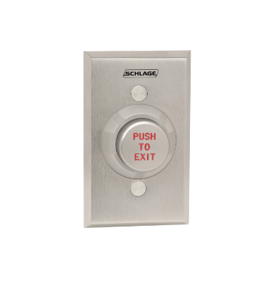
- A manual unlocking device mounted 40 to 48 inches above the floor and within 5 feet of the doors, marked PUSH TO EXIT.
- Direct interruption of power when that device is operated, independent of any other electronics, holding the door unlocked for at least 30 seconds.
- Release on fire alarm activation and on sprinkler or fire detection activation, until the system is reset.
- Emergency lighting on the egress side of the opening.
- A listed locking system, which in recent editions means listing to the relevant access control standard.
What Does the Door Hardware Release Method Require?
Door hardware release is simpler. The hardware on the door leaf has an obvious operating method usable in any lighting, works with one hand, and cuts power the moment it is operated. Loss of power unlocks the door automatically. Where panic hardware or fire exit hardware is required on that opening, operating it has to release the lock as well.
The model codes do not require a fire alarm interface or an auxiliary push button for this method, which surprises people who have only ever installed sensor release systems. Neither method is permitted in high hazard occupancies.
Why Is Every Electromagnetic Lock Fail Safe?
A direct pull maglock holds only while current flows. There is no mechanical state in which it can stay locked without power, so fail secure operation is not physically available. Both release provisions also require automatic unlocking on loss of power, which makes the physical property a code requirement as well.
Delayed egress is a separate arrangement with its own code section, not a maglock feature. A delayed egress door holds for a defined period after an alarm sounds and then releases. Our guide to what delayed egress is and when code requires it covers that arrangement in detail.
Can You Put an Electromagnetic Lock on a Fire Rated Door?
Sometimes, and the conditions are strict. The lock has to be labeled for use on a fire door assembly, because every component installed on a fire door needs its own listing. An unlabeled lock on a labeled opening is a deficiency on inspection.
The point that catches people out is latching. A maglock is a holding device, not a latch, and it does not satisfy the positive latching requirement on a fire rated opening. The required latch stays, and it has to actually latch. Positive latching is what stops smoke pressure pushing the door open and carrying fire into the next compartment.
Removing or defeating the latch bolt so a maglock can control the door is a serious deficiency. So is mounting a lock without the frame reinforcement called out in the frame manufacturer's listing, which can compromise the rating of the whole assembly.
If you are working through hardware on rated openings, our commercial door fire rating guide sets out what each rating allows, and the OEM versus aftermarket parts guide explains how substituting a component affects a listing.
Why Is My Maglock Not Holding or Not Releasing?
Almost every maglock fault traces back to alignment, power or suppression. Work the table in order rather than condemning the magnet, because the coil itself is one of the least likely parts to fail.
| Symptom | Most likely cause | What to do |
|---|---|---|
| Door can be pulled open while the system reports locked | Armature not seating flush, or voltage drop on the run | Check armature float and pole coverage first, then measure voltage at the lock under load |
| Armature will not sit flat against the magnet | Sex bolt over tightened, or wrong spacer stack for the door thickness | Back the armature bolt off slightly so the plate can pivot, and confirm the kit matches door thickness |
| Lock releases one to two seconds late | Flyback diode fitted across a DC coil | Review the suppression against the manufacturer instruction, and check whether the lock has internal suppression already |
| Audible hum or buzz at the lock | Alternating current on the direct current supply, or loose mounting hardware | Meter for AC on the DC line, confirm the supply is filtered and regulated, tighten all fasteners |
| Lock clanks or re energizes while the door is still moving | Relock timer too short | Extend the relock delay, or wire a door position switch in series so the lock cannot energize until the door is closed |
| Lock works on the bench but not installed | Shared supply overloaded, or per output fusing on the panel | Check the per output rating, not just the total rating of the supply |
| Status LED on but no hold | Collapsed voltage under load, loose connection, or a failed board | Measure at the lock with the lock connected, not just at the supply |
| Lock reads bonded but door is open | Bond sensor or reed switch fault | Bond sensing hardware does contain moving contacts and can fail. Verify against the door position switch |
Should You Fit a Diode or a Varistor Across the Coil?
Collapsing the field in a coil produces a voltage spike, and installers often fit a suppression component without checking what the lock needs. The choice changes release behaviour in a way that gets blamed on magnetism.
A flyback diode clamps at roughly one volt, so the stored energy bleeds away slowly and the magnet can keep holding the armature for a second or two after power is cut. A metal oxide varistor clamps far higher, so the energy dissipates much faster and the lock drops promptly. Diodes suit small solenoid devices such as strikes. For door magnets the varistor is generally the appropriate part.
Before adding anything, open the wiring compartment and look. Full size units frequently ship with suppression already fitted, and a second component in parallel is how a prompt lock becomes a sticky one. The common advice to degauss the armature or dimple the magnet face is not a fix, and risks damaging the machined surfaces.
When Is a Maglock the Wrong Choice?
Maglocks get specified because they are easy to fit and forgiving of door and frame condition. Those are real advantages. They also come with a code burden that an electric strike or an electrified lockset does not carry, and on some openings they are simply not the right device.
| Factor | Electromagnetic lock | Electric strike | Electrified lockset |
|---|---|---|---|
| What is modified | Frame head and door face | Frame only | Door only, plus power transfer |
| Power transfer to the door | Not required | Not required | Required |
| Fail state options | Fail safe only | Fail safe or fail secure | Fail safe or fail secure |
| Provides positive latching | No | Yes, with the lock it serves | Yes |
| Does the lever or push bar release it | Only through a switch that cuts power | Yes, mechanically | Yes, mechanically |
| Egress provisions triggered | Yes, special locking arrangement | Normally no | Normally no |
| Suits fire rated openings | Only when labeled, and latching still required | Commonly, when listed | Commonly, when listed |
Choose something else when the opening needs positive latching that a magnet cannot provide, when the door is frameless glass with no bracket clearance, or when the cost of sensors, release buttons, emergency lighting and fire alarm interface outweighs the saving on hardware. Our comparison of an electrified mortise lock versus an electric strike works through the same decision from the latching side.
Need the part, not the theory? Browse electromagnetic lock parts for armature plates, brackets, sex bolts and sensors, or use the diagram lookup across all products and parts to identify a component before you order. Call 845-935-0301 if the part you need is not listed.
About the Author
Security Parts has supplied repair parts for commercial door hardware since 2001. We stock components at the part level for the brands locksmiths actually work on, and our diagram based lookup exists so a technician can identify a component before ordering rather than after. This guide was written by the Security Parts team from supplier documentation and the questions customers bring to us.
If you are maintaining a mixed estate, our commercial door hardware maintenance checklist covers the monthly, quarterly and annual tasks that keep electrified hardware working, and the commercial door hardware troubleshooting guide covers faults across exit devices, closers, locks and strikes.