 Trusted Since 2001





The moment a lock, an exit device or a switch sits on the moving leaf instead of the frame, you need a way to carry current across the hinge line. An electric power transfer is one of three methods, and picking the wrong one is how installers end up with intermittent faults that look like a defective lock. This guide covers all three, the wire counts and current limits that decide between them, and where the prep actually goes.
Quick Summary
An electric power transfer is a hinged, armored unit mortised into the frame and the door edge that carries low voltage conductors into a moving door. The two alternatives are a through wire hinge, which needs almost no extra prep, and a surface mounted door loop, which is the cheapest and the most exposed. The choice comes down to how many conductors you need, how much current the device on the door draws, and whether the opening is labeled.
Key points
- The number in EPT-10 is the wire count, not the gauge. Ten 24 AWG conductors carry less current than the EPT-2's two 18 AWG conductors.
- Electric latch retraction is the deciding factor. A motorized device is easy to feed. A solenoid device with a large inrush is not.
- The published mounting position is about 6 inches below the top hinge. Frame prep and door prep have to align.
- Hinge width caps the door swing. Wider butt hinges reduce how far the door can open with an EPT fitted.
- You do not need a transfer for an electric strike. The strike lives in the frame, so nothing crosses the hinge line.
- On a labeled opening the cutouts normally have to be factory made, which is why retrofitting a transfer into a rated door is a problem.
| Method | Typical conductors | Best for | Main drawback |
|---|---|---|---|
| Electric power transfer | 2 or 10, depending on model | Permanent installs where wires need protecting and servicing later | Most door and frame prep, highest hardware cost |
| Electrified hinge or pivot | 4 to 12, thin gauge | Openings where prep has to stay minimal | Not designed to relieve stress on the conductors |
| Surface mounted door loop | Usually up to around a dozen thin conductors | Retrofit, tight budget, awkward routing | Visible, exposed to damage and vandalism |
In This Guide
- What is an electric power transfer and when do you need one?
- Which devices need power taken into the door?
- EPT, electrified hinge or door loop: which should you use?
- What does the 10 in EPT-10 actually mean?
- Why does electric latch retraction change the wire calculation?
- Where does an EPT mount on the door?
- Which hinges and pivots can an EPT work with?
- Can you use an electric power transfer on a fire rated door?
- What goes wrong with power transfers?
- Which templates and documents do you need?
- About the author
What Is an Electric Power Transfer and When Do You Need One?
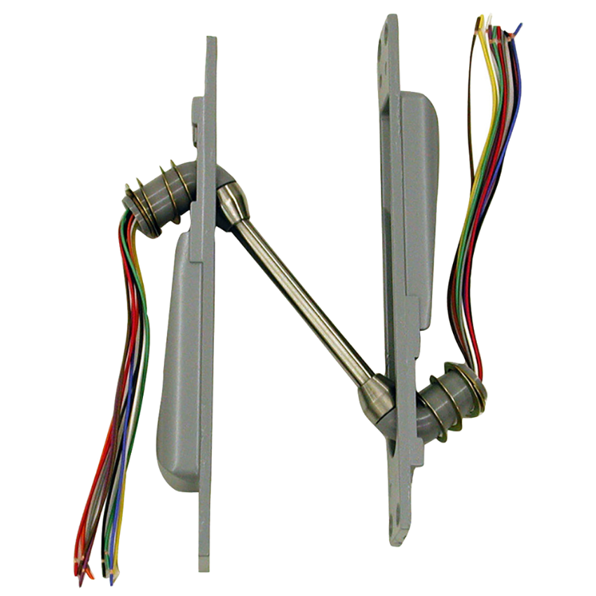
An electric power transfer is a two part armored unit. One half mortises into the frame, the other into the door edge, and a jointed arm between them carries the conductors through the swing. The joint is built so the wires flex at a controlled point instead of being bent and pinched wherever the door happens to move.
You need one whenever the electrified component sits on the leaf that moves. That is the whole test. If the powered part is in the frame, nothing has to cross the hinge line and no transfer is required.
The common Von Duprin units measure roughly 9 inches long by 1-1/4 inches by 1-5/8 inches, and the door needs to be at least 1-3/4 inches thick. The frame requires reinforcement of at least 0.060 inch to take the tapped mounting holes.
Which Devices Need Power Taken Into the Door?
This is the table that decides the specification, and it is the one most commonly skipped. Count the conductors for every function on the door, not just the lock, because the request to exit switch and the latch monitor usually get added after the frame is already set.
| Device on the opening | Transfer needed | Notes |
|---|---|---|
| Electrified lever trim | Yes | Low current. Conductor count is usually modest |
| Motorized latch retraction exit device | Yes | Low inrush, feeds comfortably through standard options |
| Solenoid electric latch retraction exit device | Yes | High inrush. Conductor gauge is the constraint, not the count |
| Electrified mortise or cylindrical lock | Yes | Check whether the lock also carries monitoring contacts |
| Delayed egress device on the leaf | Yes | Manufacturer guidance favours the larger wire transfer here |
| Request to exit switch | Yes | Signal only, but it still needs conductors |
| Latch bolt monitoring switch | Yes | Often forgotten at specification stage |
| Door mounted reader or credential hardware | Yes | Confirm conductor count with the reader manufacturer |
| Electric strike | No | Mounted in the frame |
| Frame mounted electromagnetic lock | No | Magnet is on the frame, armature is passive |
| Door position switch in the frame | No | Frame mounted switches need no transfer |
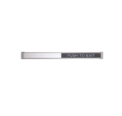
One transfer serves one powered leaf. A pair of doors with electrified hardware on both leaves needs two. If you are working out which exit device option you actually have, the Von Duprin 98/99 series parts manual lists the option codes by letter, and the QEL conversion kit guide covers what a motorized conversion involves.
EPT, Electrified Hinge or Door Loop: Which Should You Use?
All three move current across the same gap. They differ in how much prep they demand, how well they protect the conductors, and how easy they are to service when something fails years later.
| Factor | Electric power transfer | Electrified hinge | Door loop |
|---|---|---|---|
| Door prep | Mortise in the door edge plus a back box | Standard hinge prep, plus a wire hole through the frame | Surface screws only |
| Frame prep | Mortise plus tapped holes and reinforcement | Hole through the hinge reinforcement | Surface screws only |
| Conductor protection | Designed to relieve stress on the wires | Not designed to relieve stress on the wires | Armored conduit, but fully exposed |
| Visibility | Visible only when the door is open | Effectively invisible | Visible at all times |
| Supplied pre wired | Yes | Yes | Normally not |
| Relative hardware cost | Highest of the three by a wide margin | Middle | Lowest |
| Serviceability later | Best. Installs with wiring in place | Hardest. Often fitted, removed for wiring, then refitted | Easy, but easy to damage too |
| Centre hung or balanced door | Not usable | Pivot is the only practical route | Sometimes possible |
The honest summary is that the door loop wins on price and loses on everything else, the hinge wins on appearance and loses on conductor capacity, and the power transfer costs the most and causes the fewest problems over the life of the opening.
What Does the 10 in EPT-10 Actually Mean?
It is the number of conductors. Not the gauge, and not the current rating. This trips up more buyers than any other detail on the topic, because the instinct is to read a bigger number as a bigger part.
The EPT-10 carries ten 24 AWG wires. The EPT-2 carries two 18 AWG wires. Thicker conductors carry more current, so the EPT-2 is the higher capacity unit despite the smaller number in the name.
| Specification | EPT-2 | EPT-10 and EPT-10C |
|---|---|---|
| Conductors | Two | Ten |
| Wire gauge | 18 AWG | 24 AWG |
| Published continuous rating | Figures differ between the data sheet and the installation instructions. Confirm against the document for your unit | Up to 1 A at 24 VDC |
| Published maximum surge | 16 A | 16 A |
| Best suited to | Power to a device that draws real current | Signal, monitoring and lower draw trim, or several functions at once |
Worth knowing before you quote a figure to a client. The EPT-2 continuous rating is published differently in the Von Duprin data sheet and in the installation instructions. The EPT-10 figure of 1 A is consistent across both. If a specification turns on the EPT-2 number, cite which document you took it from.
Some specifiers deliberately order the ten wire unit even when two conductors would do, purely so there are spare conductors available when someone adds a monitoring function later. That is a reasonable call on a new opening, provided nothing on the door needs more current than thin conductors can carry.
Why Does Electric Latch Retraction Change the Wire Calculation?
Most electrified trim and monitoring draws very little. Latch retraction is different, because pulling the latches back takes a burst of current far above what the device needs to hold them there.
Motorized latch retraction is the easy case. A published Von Duprin figure for a motorized device is an inrush of 1.0 A for half a second, settling to 0.14 A to hold. That feeds comfortably from a standard power supply and a sensibly sized conductor.
Solenoid driven latch retraction is the hard case. Trade sources report inrush figures an order of magnitude higher, which is why these devices call for a dedicated supply or a booster module rather than being powered through an access control panel output. Panel relay contacts are frequently rated only a few amps, and panel outputs are often fused individually well below the unit's total rating.
| Conductor | Maximum run |
|---|---|
| 18 AWG | 200 feet |
| 16 AWG | 320 feet |
| 14 AWG | 500 feet |
| 12 AWG | 800 feet |
Here is the practical conclusion. Ten 24 AWG conductors rated for 1 A are correct for trim, switches and monitoring, and categorically wrong as the only power path for a high inrush solenoid device. On that kind of opening the usual answers are a two wire transfer sized for the latch retraction power with a separate route for signal, or specifying a motorized device so the inrush problem disappears.
- Size the whole run, not just the transfer. The transfer is a short, thin section in a longer circuit, and it has to be factored into the total.
- Keep the run from the transfer as short as practical. Manufacturer guidance says so explicitly.
- Do not splice a small conductor to a large one to gain capacity. Current forced through the thinner wire is a fire risk.
- Power a high inrush device from its own supply and let the access panel trigger it rather than feed it.
Where Does an EPT Mount on the Door?
On the hinge side, approximately 6 inches below the top hinge. The published measurement runs from the bottom of the top hinge to the top of the power transfer. The same position is recommended on continuous hinge doors for consistency.
The prep in the frame and the prep in the door edge have to line up, which sounds obvious and is the most common reason a transfer binds. On metal frames the unit takes tapped mounting holes in twelve places and a one inch opening through to the wire channel.
Older buildings often have the transfer much lower, sometimes between the bottom hinges. That is a legacy of a period before these units were listed, when they had to sit below a certain height on rated frames. Facilities with cart and gurney traffic tend to dislike the low position for obvious reasons.
Check the label location before you cut. On a standard height door the recommended prep position can land close to where the fire label is applied. A shop that labels its own frames can plan around it. A contractor cutting into a door and frame that arrived already labeled cannot.
Which Hinges and Pivots Can an EPT Work With?
This is the table that stops a part being ordered and then found unusable. Wider hinges push the door further from the frame as it swings, which progressively limits how far it can open before the transfer runs out of travel.
| Hinge or pivot | Door swing supported |
|---|---|
| Butt hinges up to 5 inches wide | 0 to 180 degrees |
| Offset pivots up to 3/4 inch | 0 to 180 degrees |
| Butt hinges 5-1/2 inches wide | 0 to 130 degrees |
| Butt hinges 6 inches wide | 0 to 110 degrees |
| Swing clear hinges | 0 to 90 degrees |
| Offset pivots at 1-1/2 inch | Not supported |
| Butt hinges wider than 6 inches | Not supported |
| Pocket pivots | Not supported |
| Centre hung doors and balanced doors | Not supported |
Continuous hinges work, but the hinge leaves need prepping too. Geared continuous hinge ranges are commonly supplied with standard cut outs sized for the common transfer units, and the cut out location is measured from the top of the hinge to the centreline of the opening rather than to its top edge.
On a centre pivot door there is no usable transfer position at all. The pivot itself becomes the only practical route, which means an electrified pivot rather than an EPT.
Can You Use an Electric Power Transfer on a Fire Rated Door?
Yes, when the unit carries the right listing. Common Von Duprin transfers are listed against the standards that cover fire door accessories, and some systems also need the access control listing depending on what they feed.
The complication is the prep, not the product. On a labeled opening the cutouts normally have to be made by the door and frame manufacturer under their listing. Field cutting a transfer into a door or frame that already carries a label is how a compliant opening quietly becomes a non compliant one.
That is why trade sources sometimes state flatly that power transfers cannot be retrofitted into fire rated openings. The accurate version is narrower: the device is listed, but the prep has to happen under the right conditions. For fire rated hardware in general, our commercial door fire rating guide sets out what each rating permits.
Fire rated wood doors have one extra requirement worth noting. A back box is required, and the rear knockout is the one to use rather than the bottom.
What Goes Wrong With Power Transfers?
Transfer faults are distinctive because they are movement dependent. A lock that misbehaves only at certain door positions is almost never a faulty lock.
| Symptom | Likely cause | What to check |
|---|---|---|
| Works open, fails closed or mid swing | Conductor creased or pinched at one point in the arc | Walk the door slowly through its full travel while watching the transfer |
| Intermittent operation that reads as a failing lock | Voltage drop from undersized conductors over the full run | Measure at the device under load, not at the supply |
| Dead after installation | Wires pinched between the back box and the transfer assembly | Confirm the area under the elbows is clear of connectors and splices |
| Short to earth, often on a hinge install | Conductor pushed through its insulation behind a hinge leaf | Heat shrink on the conductors and a grommet where wires pass through metal |
| Wrong part delivered to site | Conductor count fixed before the final hardware schedule | Recount every powered function on the leaf, including monitoring |
| Hinge transfer fails after a few months | Hinge leaves separated during install, breaking the wires | Electrified hinge leaves are not designed to be taken apart |
| Crushed wire chase in a steel frame | Grout or mortar packed into the frame with no guard fitted | Confirm a mortar guard was used where the frame is filled |
| No service access years later | Concealed wiring with no accessible junction | Plan a serviceable connection point at specification stage |
Two installation habits prevent most of this. Fit the strain relief that comes with the unit, and leave the elbows roughly half an inch of free movement when pulled straight out so the joint is not loaded at rest.
Which Templates and Documents Do You Need?
Three Von Duprin documents cover the common transfers, and knowing their numbers saves a long search. The template for metal frames and the template for wood doors are separate documents, and the installation instructions carry a dimensioned template on the back page.
- Metal frame template, document 107293. Covers the frame and door edge prep for the standard units.
- Wood door template, document 109342. Use this one for wood door applications rather than adapting the metal template.
- Installation instructions, document 107717. Carries the swing limits, the rating table and the dimensioned template.
Before ordering, confirm four things: the conductor count against every powered function on the leaf, the current the heaviest device draws, the hinge or pivot type and the swing the door needs, and whether the opening is labeled. Get those four right and the part fits the first time.
Need the unit or a replacement? The EPT-10 electric power transfer with ten 24 gauge wires is stocked at the part level, and you can work through Von Duprin parts or the full products and parts index with the diagram lookup. Call 845-935-0301 if you are not sure which conductor count you need.
About the Author
Security Parts has supplied repair parts for commercial door hardware since 2001, covering Von Duprin, LCN, Schlage, Falcon and Detex at the component level. Our diagram based lookup exists so a technician can confirm a part before ordering it. This guide was written by the Security Parts team from supplier documentation and the questions our customers bring us.
For the wider electrified opening, see our access control and door hardware integration guide, the comparison of an electrified mortise lock versus an electric strike, and the step by step on how to install an exit device.